
Control Line: Speed
Gene Hempel 301 N. Yale Dr. Garland, TX 75042
© 1989 Gene Hempel
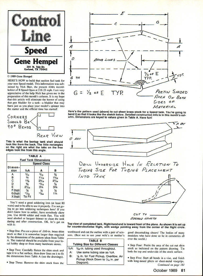
HERE'S HOW to build that suction fuel tank for your new Speed model. This information was submitted by Nick Sher, the present AMA recordholder of B Speed Open at 218.23 mph. I am very appreciative of the help Nick has given me in the preparation of this month's column. It is my hope that this article will eliminate the horror of using that pen bladder for a tank — a bladder that may burst just as you place your model's spinner into the starter and the official time has started!
This article refers to drawings and sketches. Where drawings are mentioned, see the pattern and sketches for exact shapes and measurements.
Materials and Tools
- .010-in. brass shim stock (tank shell)
- .005-in. brass shim stock (end caps)
- Brass tubing (sizes per Table B)
- 60/40 solder and rosin flux
- Soldering iron (at least 80 watts) and soldering supplies
- Vise, long-nosed pliers or sheet-metal vise grips
- Scissors (sturdy, not fine dressmaking shears)
- Files, sandpaper, steel wool
- Surgical clamps or small alligator clips
- Wood clothespins
- Alcohol or lacquer thinner (for cleaning)
- Hot tap water (for flushing)
- RTV adhesive (room-temperature-vulcanizing)
- Fuel line for testing
- Small vice for clamping tubes
Note: If you do not know how to solder, have someone show you. Proper soldering technique is essential.
Tables
Table A — Fuel Tank Dimensions
Fuel Tank Dimensions by Speed Class (see drawing). Values keyed to Table A in the pattern/drawing supplied with this article.
(Refer to the drawings for exact values of A, B, C, D, E and other dimensions.)
Table B — Tubing Size for Different Classes
- 1/2A: 3/32-in. tubing used throughout.
- A: Use same tubing size as 1/2A.
- B: 1/8-in. tubing for Fuel Pickup, Overflow, Air Pickup (neck down to 1/16 in. per diagram).
Note: The nested tubes (where used) are to be soldered together — without plugging them with solder!
Construction
- Step One: Pre-cut a piece of .010-in. brass shim stock somewhat larger than required by Table A and the pattern. The material should be available from your local hobby shop or hardware store.
- Step Two: Carefully flatten the shim stock and tape it to a flat surface, then draw the layout lines to fit the dimensions from Table A (see the drawings).
- Step Three: Remove the shim stock from the workboard and cut the outline with a pair of scissors. (Best not to use your wife's or mother's good dressmaking shears!)
- Step Four: Pretin the area of the cut-out shim stock as indicated on the pattern drawing. Tin both the top and underside of the stock surface.
- Step Five: Start all bends in a vise, and finish with long-nosed pliers or sheet-metal vise grips. When the job is done, the bent shim stock should look like the sketches near the pattern drawing. The little rectangles on the open edge are the solder tabs to be folded later.
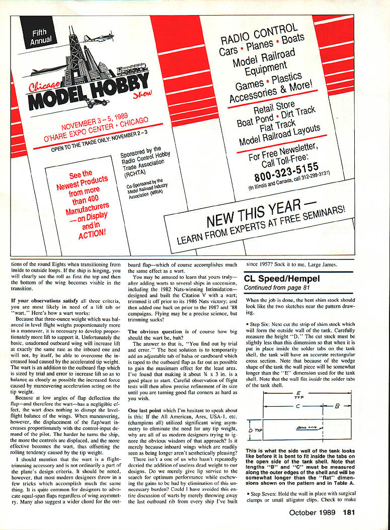
- Step Six: Cut the strip of shim stock that will form the outside wall of the tank. Carefully measure the height "D." The cut stock must be slightly less than this dimension so that when it is put in place inside the solder tabs on the tank shell, the tank will have an accurate rectangular cross section. Because of the wedge shape of the tank, the wall piece will be somewhat longer than the "E" dimension used for the tank shell. Note that the wall fits inside the solder tabs of the tank shell.
- Step Seven: Hold the wall in place with surgical clamps or small alligator clips. Check that the tabs are folded inside the tank shell and solder the wall to the shell on the inside. After soldering, trim and file the seams smooth. Note: Lengths "B" and "C" must be measured along the outer edges of the shell and will be somewhat longer than the flat dimensions shown on the pattern and in Table A.
- Step Eight: Cut three brass tubes to the desired lengths for fuel pickup, overflow, and air vent. Check Table B for the correct tubing diameter for the Speed class of the model being constructed. Be sure to follow the construction technique for the air vent tube shown in the drawings.
- Step Nine: When drilling holes in the tank for inserting tubing, make the holes undersize. The fuel pickup tube should be on the floor of the tank in the bend of the wall with the delivery end angled upward (see sketches). Hold the tube in place with wood clothespins while you solder it in place. Use a minimum amount of solder and make sure the solder fillet completely encircles the tube and penetrates into the interior of the tank. Make sure not to plug the tube with solder! Clean flux from interior and exterior of the tank.
- Step Ten: Bend the air vent tube to shape (see top view of tank). Drill an undersize hole and insert the tube. Pretin the end of the tube before inserting it into the tank. The end of the air vent tube goes directly above the fuel pickup tube’s end. Clamp the tube in place and solder the tube to the tank shell first.
- Recheck the position of the end of the tube inside the tank. Reach in from the open rear end with the iron and a long piece of solder, and tin the interior of the tank where the tube end will be anchored.
- Clamp the free end of the air tube in a vice with the rear end of the tank facing you. Clamp/wedge the pretinned end of the air tube in the desired place, then touch the iron to the pretinned outside area of the tank to solder the pretinned tube end inside the tank.
- Do not hold the iron on the tank too long or you may disturb the joint holding the fuel pickup tube.
- Inspect the interior joint for a good fillet of solder and for the tubes still being unplugged. Thoroughly clean the flux from the tank.
- Step Eleven: Cut the overflow tube to the desired length, drill an undersize hole into the tank wall, and insert the tube just enough to allow a nice solder fillet to be formed around it. Check the drawing for placement of the tube. Thoroughly clean the flux from the tank.
- Step Twelve: Soak the tank in alcohol or lacquer thinner, then run hot tap water through the tank to flush out any grindings and residual flux.
- Step Thirteen: Place the end of the tank over a piece of .005-in. brass shim stock, pencil an outline on the brass, and scribe the outline into the brass allowing a 1/8-in. overlap on all sides for solder flaps. Cut out the end piece, bend the flaps, and position the part on the end of the tank to check the fit. Remove the end piece and pretin the solder flaps and the edges of the tank where they will mate. Put the end back on the tank and solder it in place. Start with the soldering iron on one corner and move the iron around the tank until a smooth fillet is formed. Clean the tank thoroughly both inside and out, then check the seams for any voids or pinholes.
- Step Fourteen: Repeat Step Thirteen for the other end cap of the tank.
- Step Fifteen: Immerse the completed tank in flux solvent or lacquer thinner for several hours. Slosh the tank in the fluid to make sure the interior is clean.
- Step Sixteen: Check the tank for leaks by connecting the fuel pickup and overflow tubes with a piece of fuel line. Place a long piece of fuel line on the air pickup tube. Immerse the tank in a basin of water, put the free end of the fuel line in your mouth and blow into it. Look for air bubbles escaping or forming at any of the solder joints on the tank. Rework as required.
- Step Seventeen: Buff the exterior of the tank with steel wool so it looks good. Plug all the tubes first before buffing.
- Step Eighteen: Rough up the inside of the speed pan with heavy sandpaper where you plan to mount the fuel tank. Rough up the part of the tank which will mate with the pan in a similar manner, then thoroughly clean both the tank and the pan before applying RTV adhesive to the area. Press the tank in place and keep it under light pressure while the RTV sets. Any of the RTV adhesives on the market will work for this application.
- Step Nineteen: Form the free end of the air pickup tube so that it is away from the side of the fuselage. Appropriate gaps are:
- 3/32 in. for 1/2A
- 1/8 in. for A
- 5/32 in. for B
The end of the air pickup tube should be positioned so that it faces into the propeller airflow.
Final Notes and Acknowledgements
I hope my loyal readers enjoyed this article — it takes an immense amount of work to pull such a piece together. My thanks once again to Nick Sher for his help.
Please remember to gather up all those bits and pieces of information, photos, etc. you have lying around. Mail them to me for inclusion in our CL Speed column!
That's all for this time.
Transcribed from original scans by AI. Minor OCR errors may remain.

