
Control Line: Speed
Glenn Lee 819 Mandrake Batavia, IL 60510
Introduction
I never really stopped to realize just how many people read this column. Any place I go I meet modelers who comment about things I've written, and I've received letters from R/C fliers, racing people, free fliers, sport fliers, and speed fliers. Guess I'd better get my stuff together!
A question I asked about where speed contests started brought several responses from early-day speed fliers all over the country and even from England. Below is a summary of what I've gathered so far.
Early contests and champions (1941)
- The First Official Speed and Aerobatic Competition for Controlled Gas Models was held in July 1941 at Lakewood Stadium, Long Beach, California. The Bunch Tiger Aero engine was cited in an advertisement as the winning motor.
- Dean McMillian became Aerobatic National Champion (using a Tiger Aero–powered A.J. Fireball).
- Bud Warren became Gas Model Speed Champion with a recorded speed of 70.58 mph (also flying a Fireball).
- Competition apparently expanded that summer. At the California State Championship in San Francisco the same year, three events were flown with the same airplane.
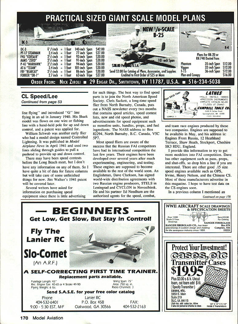
- The Dayton, Ohio "Cold Cash Speed Bash" has been held every September, with contestants coming from as far as Texas, New York, and Iowa.
- Other 1941 meet winners mentioned in the material:
- Charles Werle won Precision Flying, Aerobatics, and Speed (with a Tiger Aero–powered Fireball).
- Pat Petrosino won the speed event at the Newark Air Show (September 14).
- A young flier, Johnny Clemens, was Speed Champion at the Dallas Southwest Gas Model Championship (flying a Fireball).
I am still trying to find exact rules used for the different events. If anyone knows, please let me know.
Early pioneers and designs
- Ron Moulton's Control Line Manual (1961) contains an excellent chapter on how control line flying started. He notes that the Stanzel brothers were flying tethered gas-powered models as early as 1939 in Texas.
- Victor Stanzel claimed to be first in control-line flying and introduced "G" line flying in an advertisement in January 1940. His Shark model was reportedly flown on one wire or fishing line with a hand-held pole for up-and-down control; a patent was applied for.
- William Schwab was another early flier. His design, Controlled Lightning, was published in Model Airplane News in April 1941 and used two lines sliding through guides to pull a pushrod for up-and-down control.
- There may have been speed contests before the Long Beach meet, but I have no firm information on those yet. I plan to cover Jim Walker's 1941 patent and other material in future columns.
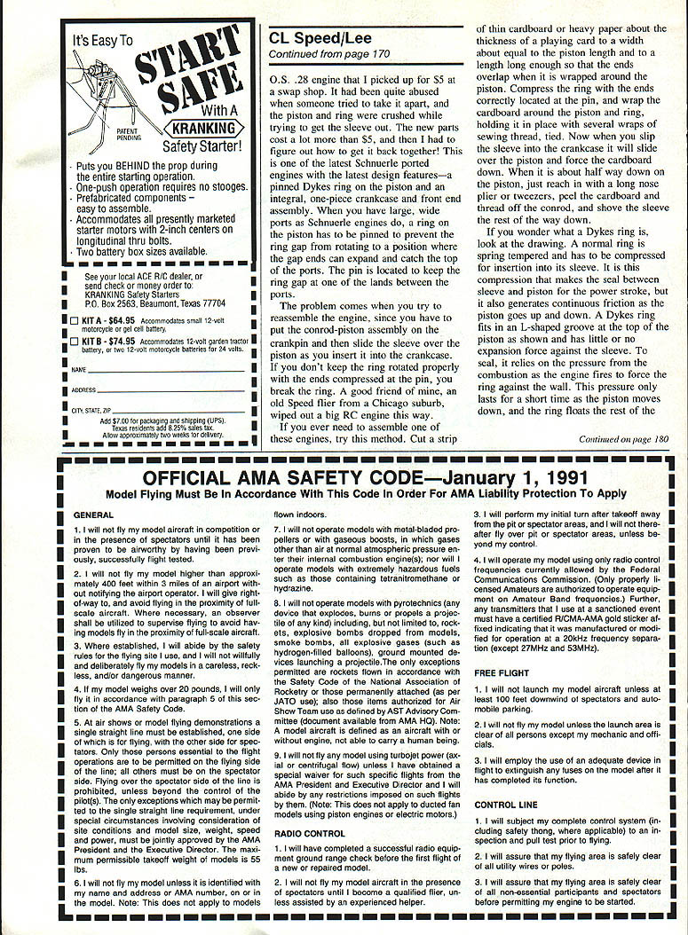
Speed equipment and where to find it
Several readers have asked about purchasing speed equipment; there is relatively little advertising for such items. The best way to find speed parts is to join the North American Speed Society (NASS).
- NASS produces a newsletter every two months with speed articles, contest lists, photos (new and old), and advertisements for equipment such as monoline units, handles, props, and fuel ingredients.
- NASS contact:
- Box 82294, North Burnaby, B.C., Canada, V5C 3P7.
International engines and distribution
Most speed fliers are aware of the success Russian FAI competitors have had in international competition over the past few years. Their engines were developed after considerable experimentation and testing, and they were expected to become available internationally.
- An Englishman, Dave Clarkson, signed worldwide distribution agreements with two Russian engine producers:
- STELS (Leningrad)
- CYCLON (Novosibirsk)
- Dave Clarkson and his partner Ed Needham are authorized agents for the speed, combat, and team race engines produced by these companies. Engines were expected to be available in May (year not specified).
- Contact for Engines From Russia:
- Engines From Russia, 12 Heathland Terrace, Shaw, Heath, Stockport, Cheshire SK3 8DU, England.
Other engines of interest (commonly available or advertised):
- OPS
- Irvine
- Henry Nelson
- Chinese CS
I hope to have test data on the CS engines soon.
O.S. .28 engine—repair and assembly notes
In a previous column I mentioned an O.S. .28 engine I picked up for $5 at a swap shop. It had been badly abused when someone tried to disassemble it; the piston and ring were crushed while attempting to remove the sleeve. Replacement parts cost far more than $5, and then I had to figure out how to reassemble it.
This O.S. .28 is a Schnuerle-ported engine with modern design features: a pinned Dykes ring on the piston and an integral one-piece crankcase and front-end assembly. With Schnuerle-ported engines, the piston ring must be pinned to prevent the ring gap from rotating to a position where the gap ends can expand and catch the top of the ports. The pin keeps the ring gap aligned at one of the lands between the ports.
The tricky part is reassembly: you must place the conrod-piston assembly onto the crankpin and then slide the sleeve over the piston and into the crankcase. If the ring end gaps are not correctly oriented and compressed at the pin, the ring will break when the sleeve is forced over it.
Suggested assembly method:
- Cut a strip of thin cardboard or heavy paper about the thickness of a playing card. Make the strip as wide as the piston length and long enough to wrap around the piston with overlapping ends.
- Compress the Dykes ring and position the ring ends correctly at the pin.
- Wrap the cardboard around the piston and ring and secure it with several wraps of sewing thread, tied.
- Slide the sleeve into the crankcase. The sleeve will slide over the piston and force the cardboard down.
- When the sleeve is about halfway down the piston, reach in with a long-nose pliers or tweezers, peel the cardboard and thread off the conrod, and push the sleeve the rest of the way down.
This method protects the ring during sleeve insertion and prevents damaging the pinned ring.
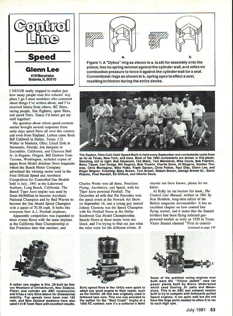
What is a Dykes ring?
- A normal piston ring is spring-tempered and is compressed for insertion into its sleeve; this compression creates a continuous sealing force against the sleeve during motion, producing friction.
- A Dykes ring fits into an L-shaped groove at the top of the piston and has little or no expansion force against the sleeve when not under combustion pressure.
- To seal, the Dykes ring relies on combustion pressure when the engine fires to force the ring against the cylinder wall. This pressure is present briefly as the piston moves down; after that the ring floats for the remainder of the stroke, reducing continuous friction.
Closing notes
I provide this information to encourage more modelers to try FAI competition and speed flying. Dave Clarkson carries related equipment such as pars, props, and shut-offs — contact him if interested. There are other good .15-size speed engines available and advertised in the hobby press; shop around and consider joining NASS for community support and sources.
If you have additional historical information, contest rules from the early meets, or corrections to the names and dates above, please write and let me know. I plan to follow up on several unfinished items in future columns.
Transcribed from original scans by AI. Minor OCR errors may remain.

