
Control Line: Speed
Glenn Lee, 819 Mandrake Dr., Batavia, IL 60510
Introduction
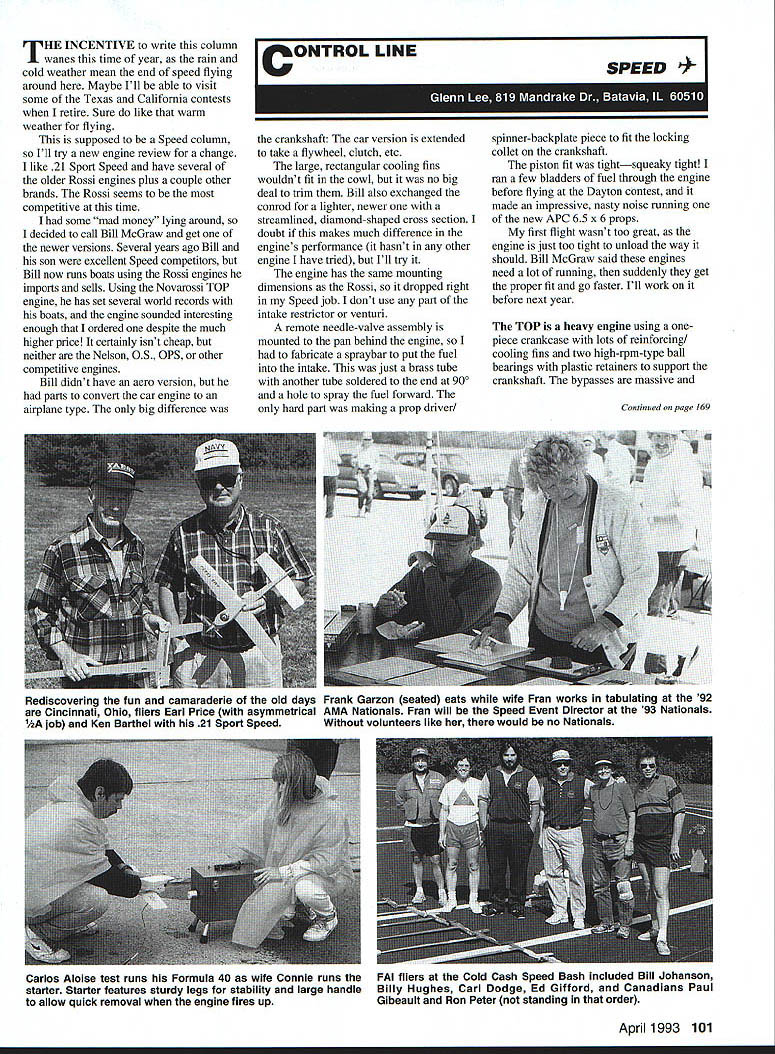
The incentive to write this column wanes this time of year as the rain and cold mean the end of speed flying around here. Maybe I'll be able to visit some Texas and California contests when I retire — I sure do like warm weather flying.
This is supposed to be a Speed column, so I'll try an engine review. I like .21 Sport Speed and have several of the older Rossi engines plus a couple other brands. The Rossi seems to be the most competitive at this time. Several years ago Bill McGraw and his son were excellent speed competitors; Bill now runs boats using the Rossi engines he imports and sells. Using the Novarossi TOP engine, he has set several world records with his boats, and the engine sounded interesting enough that I ordered one despite the much higher price. It certainly isn't cheap, but neither are the Nelson, O.S., OPS, or other competitive engines.
Ordering and conversion
Bill didn't have an aero version, but he had parts to convert the car/boat engine to an airplane type. The big difference was the crankshaft: the car version is extended to take a flywheel, clutch, etc. The large, rectangular cooling fins wouldn't fit in the cowl, but trimming them was no big deal. Bill also exchanged the conrod for a lighter, newer one with a streamlined, diamond-shaped cross section. I doubt this makes much difference in performance (it hasn't with other engines I've tried), but I'll try it.
The engine has the same mounting dimensions as the Rossi, so it dropped right into my Speed job. I don't use any part of the intake restrictor or venturi. A remote needle-valve assembly is mounted to the pan behind the engine, so I fabricated a spraybar to put fuel into the intake. This was just a brass tube with another tube soldered to the end and a 0.090" hole to spray the fuel forward. The only hard part was making a prop-driver/spinner-backplate piece to fit the locking collet on the crankshaft.
Installation and initial running
The piston fit was tight — squeaky tight. I ran a few bladders of fuel through the engine before flying at the Dayton contest, and it made an impressive, nasty noise, not too nice running on the new APC 6.5 x 6 props. The first flight wasn't too great, as the engine is just too tight to unload the way it should. Bill McGraw said these engines need a lot of running; then suddenly they get the proper fit and go faster. I'll work on it before next year.
Engine construction and features
The Novarossi TOP is a heavy engine using a one-piece crankcase with lots of reinforcing cooling fins and two high-rpm ball bearings with plastic retainers to support the crankshaft. The bypasses are massive and quite deep. The exhaust port is beveled and streamlined to allow unrestricted flow of gases. The rectangular exhaust opening uses a sleeve and a round O-ring–sealed mini-pipe.
Almost all the latest high-performance engines utilize machining relief in the crankcase opposite the intake opening. The relief increases clearance between the rotating shaft and case, reducing viscous drag of oil and fuel. Areas around the intake opening just behind the front bearing are close-fitting to retain crankcase compression.
A small radial hole in the crankshaft, opposite and slightly behind the intake opening, allows oil to be thrown out to make sure the area between the ball bearings is lubricated. A small hole in the crankcase allows some oil flow toward the intake. The large hole drilled into the crankshaft is offset to the opposite side to make the intake port leave the wall thicker around that opening.
Most crank failures occur when a crack starts at a corner of the intake opening, so the TOP has rounded corners in this area to eliminate stress concentration. The beginning of the crankshaft hole — the end where the conrod clears — is beveled on the side opposite the crank pin. This is the so-called turbo crank; this bevel will supposedly throw the incoming fuel-air charge out into the case, acting like a turbocharger. I wonder how much effect it really has.
Exhaust sleeve and ports
The chrome-plated brass exhaust sleeve is unlike any I've seen before. It has 10 bypass ports and one large exhaust port. The exhaust port is wide at the top, encompassing about 90° of the bore circumference, then tapers at the bottom. The angle formed matches the angle of the bypasses in the case.
On each side of the exhaust port is a very narrow, long port similar to a Perry directional port, with the top edge even with the Schnuerle ports. The two Schnuerle ports are typical, except the top edge is beveled upward at a slight angle instead of being square to the bore centerline — presumably to direct the incoming charge straight across the piston.
Two boost ports are directly across from the exhaust port, angled slightly towards the center, with the top edges beveled upward about 45°. Another narrow port is located on each side between the boost port and the Schnuerle port. All four of these narrow ports are only about 0.040 in. wide by 0.400 in. long. Apparently they let some of the fuel-air charge in or out from beneath the piston, since the bottom part of these slots is open when the piston is near the top of the stroke.
Two more small ports about 3/32 in. wide directly under the Schnuerle ports match two holes in the side of the piston when it is near bottom dead center. These apparently vent the underside of the piston for increased cooling as well as allowing more charge into the bypass.
Timing and performance
Timing doesn't seem radical. The top edge of each exhaust port is not level: the center stays open for 168° and the ends for 162°. All eight bypass ports are open for 128°. The crankshaft intake port opens about 35° ABDC (after bottom dead center) and closes 58° ATDC (after top dead center).
The piston appears to be a typical high-silicon casting, with a half-moon cutout on the front skirt to clear the crank at BDC. This allows more of the incoming charge to get into the boost bypass. The top edge is beveled to fit the taper of the sleeve and reduce break-in time, and the wrist pin is held in with two circlips.
The bore-to-stroke ratio is closer to square than most engines being built today: bore = 0.648 in., stroke = 0.645 in. This doesn't seem to hinder high-revving capabilities.
The head fits about 0.150 in. deep into the sleeve and is a two-piece design like the Rossi, except the clamp flange extends to the full diameter of the head. The combustion chamber is relatively small at 0.365 in. diameter, but deep at 0.136 in. The wide squish band has a slight taper to avoid a hydraulic lock when the piston is at TDC. The black-anodized clamp ring is held on with four metric-head bolts.
The backplate has a circular groove cut so the piston skirt doesn't hit at BDC, and is sealed to the case by an O-ring. When you reassemble the engine, make sure this groove is on top.
Planned modifications
- Open the crank to close nearer to 70° ATDC.
- Fit the piston a little more loosely — this is tricky because it's easy to make the piston too loose.
- Consider a new airplane as a potentially bigger improvement.
- Possibly try a 28% silicon piston.
I'll work on break-in and any modifications before next spring.
Transcribed from original scans by AI. Minor OCR errors may remain.

