
Control Line: Speed
Glenn Lee 819 Mandrake Dr., Batavia, IL 60510
Bellcranks and Control Linkage
As I write this, a new year is starting, winter has set in, and modelers around here are supposed to be building new airplanes for next year. I could use about three new Speed jobs, so I'd better get busy! Control line is booming, and our club, the Tree Town Modelaires, has almost doubled in size, so it should be a good year. I'll try to cover a variety of topics in this column to help prospective competitors.
I still get letters and questions from modelers who want to buy or make suitable bellcranks for two-line Speed models. These fliers are interested in .21 Sport Speed or Formula 40. I have three or four different ways to fabricate bellcranks; they all seem to work, and the type I use just depends on how much work I feel like doing.
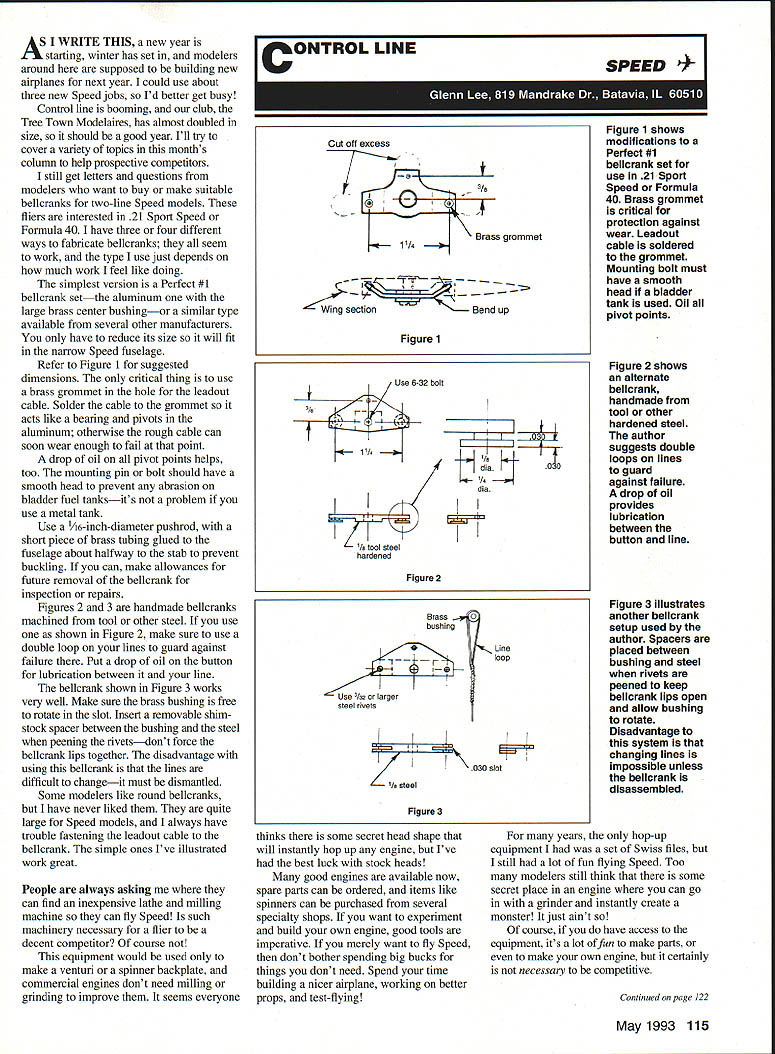
- The simplest version is a Perfect #1 bellcrank set (the aluminum one with the large brass center bushing) or a similar type available from several other manufacturers. You only have to reduce its size so it will fit in the narrow Speed fuselage. Refer to Figure 1 for suggested dimensions. The only critical thing is to use a brass grommet in the hole for the leadout cable. Solder the cable to the grommet so it acts like a bearing and pivots in the aluminum; otherwise the rough cable can soon wear enough to fail at that point. A drop of oil on all pivot points helps, too. The mounting pin or bolt should have a smooth head to prevent any abrasion on bladder fuel tanks—it's not a problem if you use a metal tank.
- Use a 1/16-inch-diameter pushrod, with a short piece of brass tubing glued to the fuselage about halfway to the stab to prevent buckling. If you can, make allowances for future removal of the bellcrank for inspection or repairs.
- Figures 2 and 3 show handmade bellcranks machined from tool or other steel. If you use one as shown in Figure 2, make sure to use a double loop on your lines to guard against failure there. Put a drop of oil on the button for lubrication between it and your line.
- The bellcrank shown in Figure 3 works very well. Make sure the brass bushing is free to rotate in the slot. Insert a removable shim-stock spacer between the bushing and the steel when peening the rivets—don't force the bellcrank lips together. The disadvantage of this bellcrank is that the lines are difficult to change—it must be dismantled.
Some modelers like round bellcranks, but I have never liked them. They are quite large for Speed models, and I always have trouble fastening the leadout cable to the bellcrank. The simple types described above work great.
Tools, Engines, and Shop Equipment
People are always asking me where they can find an inexpensive lathe and milling machine so they can fly Speed! Is such machinery necessary for a flier to be a decent competitor? Of course not. This equipment would be used only to make a venturi or a spinner backplate, and commercial engines don't need milling or grinding to improve them.
It seems everyone thinks there is some secret head shape that will instantly hop up any engine, but I've had the best luck with stock heads. Many good engines are available now, spare parts can be ordered, and items like spinners can be purchased from several specialty shops.
If you want to experiment and build your own engine, good tools are imperative. If you merely want to fly Speed, then don't bother spending big bucks for things you don't need. Spend your time building a nicer airplane, working on better props, and test-flying!
For many years, the only hop-up equipment I had was a set of Swiss files, but I still had a lot of fun flying Speed. Too many modelers still think there is some secret place in an engine where you can go with a grinder and instantly create a monster—it just ain't so! Of course, if you do have access to the equipment, it's a lot of fun to make parts, or even to make your own engine, but it certainly is not necessary to be competitive.
Control Line: Speed
Finish and Visibility
When you have your new airplane built, try to pick a highly visible color for the finish. The Dayton Buzzin' Buzzards have many years of complete records of their Speed contests. They compared stopwatch readings versus airplane color, and found that the recorded times were much closer for light-colored airplanes than for dark ones. Recorded times for bright yellow airplanes were consistently close, and those for white airplanes were second.
Last fall, Paul Gibeault had his FAI model painted with neon orange—the brilliant fluorescent, high-visibility paint. These thin, sidewinder-type airplanes are very difficult to see at speeds over 170 mph, but his could easily be timed.
Switching Fuels: High-Nitro to 10% — What to Do to the Engine
Speed fliers and racing modelers have asked me what to do to their engines when switching from high-nitro fuel to the 10% stuff. I'm not really positive what is best, but I have a theory and I'm still experimenting. You should do your own test-flying to see if my idea has any merit.
In an ABC engine, as most high-performance engines are now, the fit and shape of the sleeve and piston are the most critical parameters for maximum speeds. When I was running 80% nitro, it seemed that the rule was: the tighter it is, the better it ran.
I ran engines that would squeak when the piston was turned past compression. My best K&B .40S, for instance, would not be turned over slowly at all—the prop could barely be flipped over when the engine was cold, but it was okay as soon as the engine warmed up just a little. This indicated that the coefficient of thermal expansion of the brass sleeve was greater than that of the high-silicon-alloy piston.
The engines run much hotter on the high-nitro fuels than they do on the 10%, so the sleeve is not going to expand as much. To reduce drag between the piston and sleeve and reach high rpm, the piston fit should not be as tight for the low-nitro fuel. Does that make sense? Test-flying will tell.
Compression ratio is another confusing area when you switch from high-nitro to low-nitro fuel. I used to run Hustad and Roy's Rattler high-compression trumpet head so close that it almost touched the piston when I flew with high-nitro and propylene oxide ignitor fuel. Now, with low-nitro fuel, it seems that the engines just can't develop enough power to compress the air-fuel charge.
I have to run with squish-band clearances of .006, .008, or even .012 inch. It even helps to increase the distance from the top of the piston to the face of the glow plug. I have to allow the engines to rev to higher rpm to regain power. Test-flying is the only way to find out exactly what each engine needs to go fast.
Transcribed from original scans by AI. Minor OCR errors may remain.

