
CONTROL LINE: SPEED
By Glenn Lee, 819 Mandrake Dr., Batavia, IL 60510
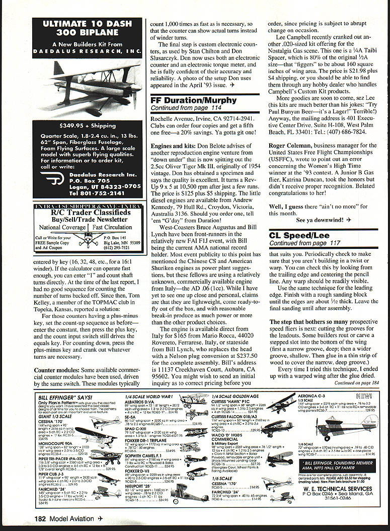
If you are contemplating building a new .21 Sport Speed airplane, you might check out Nick Arpino's new magnesium pan. Even the heavy-bodied Rossi engine will easily drop into this pan with a minimum of metal removal.
I have used Nick's longer Class-A pan before, but had to add metal lumps to the outside to prevent grinding through the wall when fitting the massive crankcase lugs inside. I found a welder who had a magnesium welding rod, and he just piled up the metal where I told him to. These irregular lumps were ground to shape with my Dremel tool, then filed, sanded, and polished with the rest of the pan.
The new pan eliminates that problem. The design is similar to the FAI machine-turned pans—short, with a ring at the back—so you can just saw off the top half of that ring if you want to use it as a half-pan.
Props
Proper speed props can be difficult to obtain. There are several suppliers of handmade fiberglass or fiberglass-carbon fiber props in this country, Europe, and Australia, but these props are expensive. It is not unusual to scrape up a prop on every landing, unless you add landing gear on your Speed jobs as on a Formula 40.
I have used several of the new APC propellers. They are inexpensive, and they work. Landing Products Company has listened to competition fliers as well as sport fliers, and it produces almost any size prop you could desire. There are suitable sizes for the .21 and .40, and even a 9 x 10 for .65s. Just check the ad, have your hobby shop order them for you, or order direct.
When the APC props first came out, some of them flew apart when used on high-output competition engines, especially Combat engines. The new props have longer reinforcing fibers that keep them together. These fibers are not glass, so they are easy to file down if you want to change shape or diameter.
You can also change the pitch by heating the prop with a hot-air gun, twisting the blade, and then dipping it in cold water while you hold the twist. I used one of the 6.5 x 6 props on my TOP Rossi .21 last fall, and it turned over 142 mph — not bad for the first flight on that engine.
Fuselage and general layout
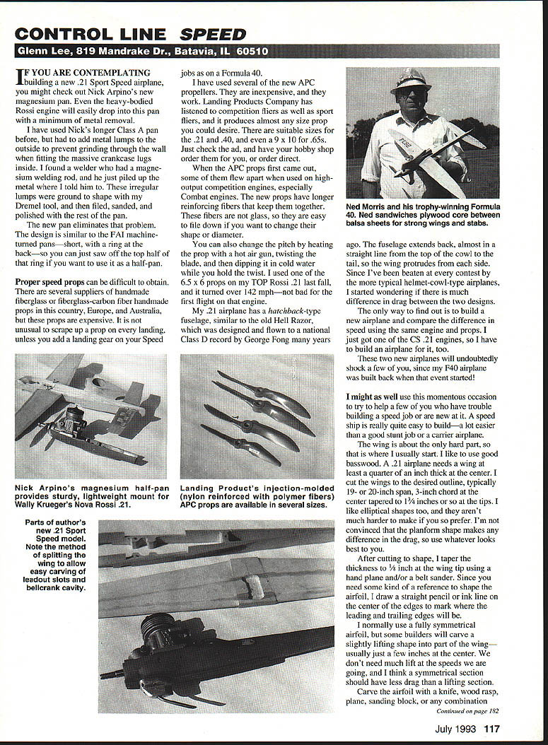
My .21 airplane has a hatchback-type fuselage, similar to the old Hell Razor, which was designed and flown to a national Class D record by George Fong many years ago. The fuselage extends back almost in a straight line from the top of the cowl to the tail, so the wing protrudes from each side. Since I've been beaten at every contest by the more typical helmet-cowl-type airplanes, I started wondering if there is much difference in drag between the two designs.
The only way to find out is to build a new airplane and compare speed using the same engine and props. I just got one of the .21 engines, so I have to build an airplane for it, too. These two new airplanes will undoubtedly shock a few of you, since my F40 airplane was built back when that event started!
I might as well use this momentous occasion to try to help a few of you who have trouble building a speed job or are new at it. A speed ship is really quite easy to build — a lot easier than a good stunt job or a carrier airplane.
Wing construction
The wing is about the only hard part, so that is where I usually start. I like to use good basswood. A .21 airplane needs a wing at least 1/4" thick at the center. Typical dimensions I use are:
- Span: 19" or 20"
- Chord at center: 3"
- Tip chord: about 1-3/4"
- Thickness at tip after tapering: 1/8"
I like elliptical shapes too, and they aren't much harder to make. I'm not convinced that the planform shape makes any difference in drag, so use whatever looks best to you.
After cutting to shape, taper the thickness to 1/8" at the wing tip using a hand plane and/or a belt sander. Since you need some kind of reference to shape the airfoil, draw a straight pencil or ink line on the center of the edges to mark where the leading and trailing edges will be.
I normally use a fully symmetrical airfoil, but some builders will carve a slightly lifting shape into part of the wing—usually just a few inches at the center. We don't need much lift at the speeds we are going, and I think a symmetrical section should have less drag than a lifting section.
Carve the airfoil with a knife, wood rasp, plane, sanding block, or any combination that suits you. Periodically check to make sure you aren't building in a twist or warp. You can check this by looking from the trailing edge and centering the pencil line. Any warp should be readily visible.
Use the same technique for the leading edge. Finish with a rough sanding block until the edges are about 1/32" thick. Leave the final sanding until after assembly.
Leadouts and slots
One step that bothers many prospective speed fliers is cutting the grooves for the leadouts. Some builders rout or carve a stepped slot into the bottom of the wing (first a narrow groove, deep; then a wider groove, shallow). Then glue in a thin strip of wood to cover the narrow, deep groove. Every time I tried this, I ended up with a warped wing after the glue dried.
I prefer to use the method shown on the plan. Cut two vee-shaped slots in the bottom of the wing with a thin, sharp chisel. The slots are centered 7/16" apart and are slanted back slightly to match the leadout angle. Cut the slots about 3/16" deep at the center, tapering to 1/16" depth at the tips. Make the entrances to the slots rounded so the wire will not be stressed.
Another technique I use is to draw the lines where I want the leadouts, then saw along those lines from wing tip to wing tip with a thin-bladed jigsaw. The wing is then in three pieces, and it's easy to carve or grind the grooves for the wires. The best tool I've found for this job is an X-Acto grooving tool. Gouge a half-round in each mating part where the wires will be, fill the grooves with resin or finishing epoxy, and glue the pieces back together. Using rubber bands for clamps, carefully align the three pieces to maintain the airfoil shape.
Next, carve extra room at the wing tip to glue in 3/32" O.D. brass tubing line guides about an inch long, reinforce this tip with lightweight fiberglass, and make the groove wide at the center for line-loop clearance when the bellcrank pivots. Running a 1/16" wire through the groove before the glue sets ensures there will be a clear opening for the wires.
Bellcrank and controls
The bellcrank is mounted in a small plywood box about 3/8" deep, 1-1/4" long, and 3/4" wide. The pushrod goes through a small tube in the fuselage and connects to the bellcrank. I use a short length of 1/16" stainless steel tubing for the pushrod guide. The bellcrank hole should be slightly larger than the bellcrank shaft so the shaft rotates freely but does not wobble. Mount the bellcrank so the leadouts are tangent to the wing when the control is neutral.
Fuselage construction
The fuselage is built around a 3/16" x 3/4" basswood keel. The engine mounts directly to the keel with plywood doublers under the firewall. The cowl is a simple hatch-type cowl held in place by rubber bands.
Alternate wing method (Ned Morris)
Ned Morris likes to make his wings out of balsa with a plywood core. He cuts the plywood to the shape he wants, cuts slots for the leadouts, and then laminates a balsa sheet on each side with instant glue. First, cover your table with waxed paper so you don't glue anything to it!
A special trick is required so the plywood is really well bonded to the balsa. Ned covers the plywood with a good layer of glue—not the thin stuff. Then he sprays the balsa with accelerator and presses the balsa against the plywood. It sets instantly, so have it lined up and be sure to press against a nice flat surface.
Next month, I'll try to have some test results.
Transcribed from original scans by AI. Minor OCR errors may remain.

