
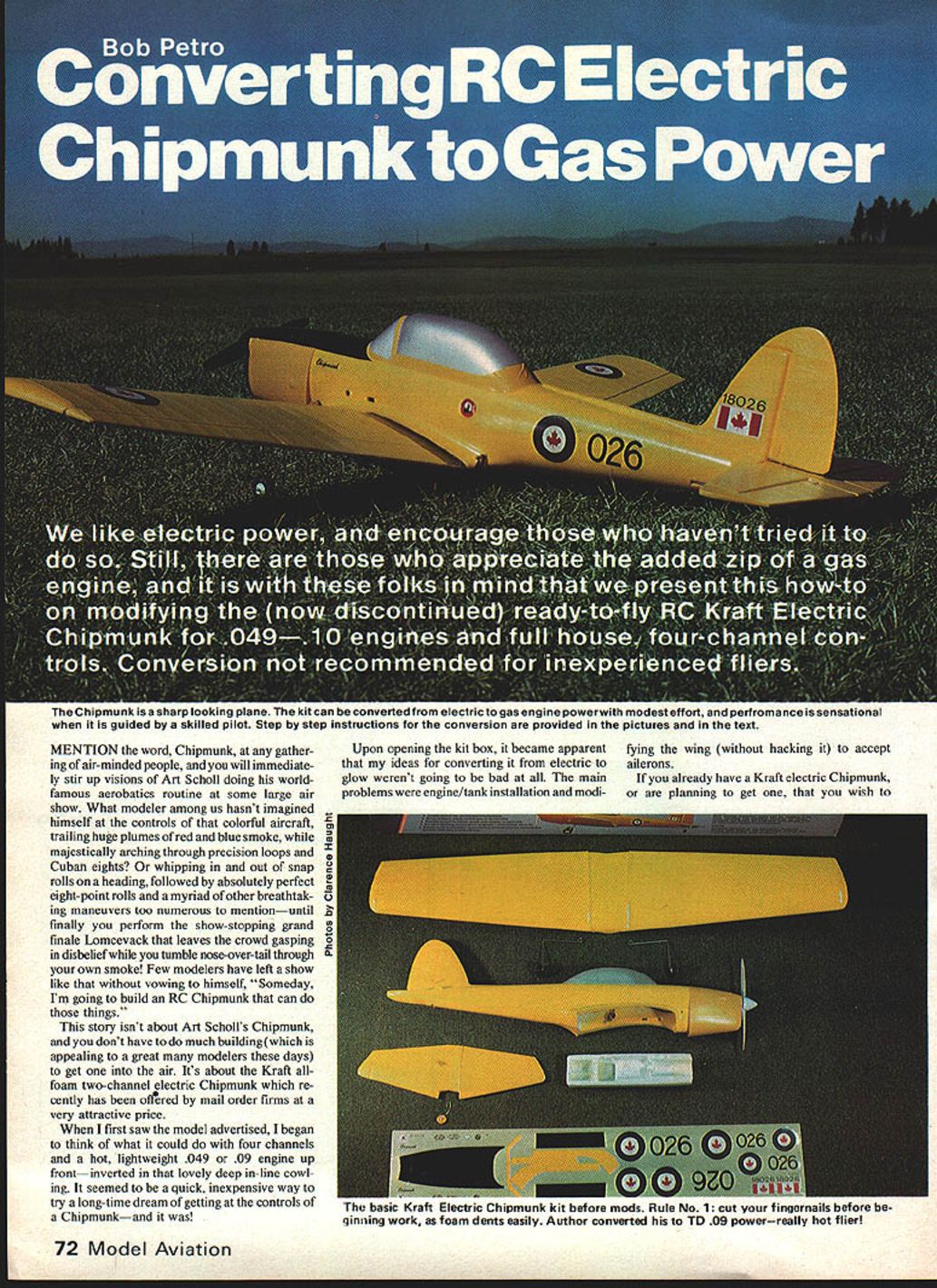
Converting RC Electric Chipmunk to Gas Power
Bob Petro
We like electric power and encourage those who haven't tried it to do so. Still, some modelers appreciate the added zip of a gas engine. This how-to shows how to modify the (now discontinued) ready-to-fly Kraft all-foam electric Chipmunk for .049–.10 glow engines and full four-channel controls. Conversion is not recommended for inexperienced fliers.
Mention the word "Chipmunk" at any gathering of air-minded people and you'll stir up visions of Art Scholl's world-famous aerobatics. Many modelers have dreamed of piloting a Chipmunk capable of precision loops, Cuban eights, snap rolls, and an eye-popping Lomcevack finale. You don't have to do much building to get a convincing Chipmunk in the air — the Kraft electric kit is an affordable, quick starting point for converting to glow power.
The main challenges for conversion are engine/tank installation and modifying the wing to accept ailerons without heavy structural hacking. Study the steps and photos carefully; with modest time and expense you'll have an eye-catching, aerobatic model.
Hardware and supplies
- Engine
- Any Cox TD .049 or .09 provides plenty of power. A Medallion will suffice. A Cox Black Widow would work but requires a different mounting system.
- Fuel tank
- Sullivan SS-3 2‑oz (about 60 ml). It provides roughly 6 minutes for a TD .09 and fits well in the equipment tray forward of the firewall.
- Miscellaneous
- Pactra Formula U paint, aviation yellow (jar or spray)
- 1/16‑in. dia. music wire, 3 ft
- 1/16‑in. inside-diameter brass or aluminum tubing, ~12 in
- Birch 5‑ply plywood (approx. 1/4 x 2 x 2 pieces as required)
- 4-40 blind nuts (4)
- Hobbypoxy Formula 2 and Formula 4
- 1/16‑in. inside-diameter flanged eyelets (4)
- 1/16‑in. inside-diameter wheel collars (4)
- 4-40 x 3/8‑in. screws (for aileron control attachment)
- Aileron control horns or two Goldberg self-threading horn brackets / strip aileron horn set
- 3/4‑in. Scotch Transparent Magic Mending Tape (or Mylar adhesive tape) for hinges
- Optional: pair Ace wheels (1/2‑in or 1‑in per availability)
- Servo mounting tape
- Scuff Guard for wingtips
- Hot Stuff Super‑T
- Small battery pack (250 mAh recommended), foam rubber for packing
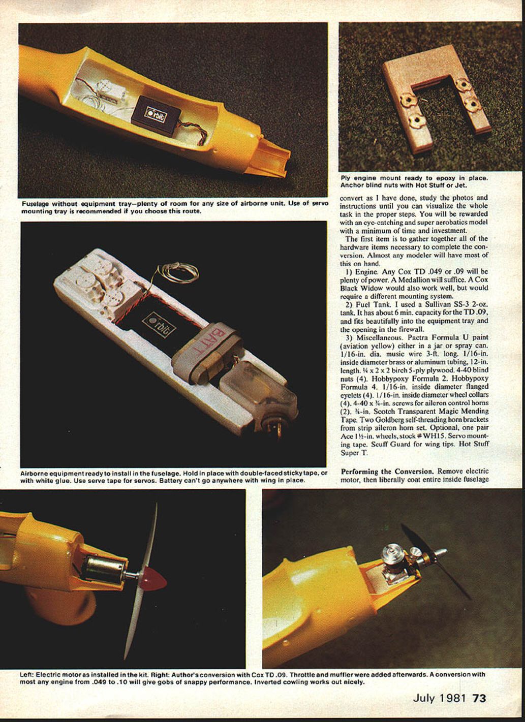
Performing the conversion
Fuselage and equipment tray
- Remove the electric motor and liberally coat the entire inside of the fuselage where the motor was installed.
- Cut out the front wall of the servo/equipment tray to accommodate your chosen fuel tank and create a flat mounting surface by removing some foam from the bottom of the tray.
- Use a servo mounting tray as recommended or arrange airborne equipment to suit. A forward compartment for the receiver allows room for an upright throttle servo just forward of the rudder and elevator servos.
- Hold the equipment in place temporarily with double-faced sticky tape and white glue while checking clearances. Use servo tape to secure servos. Wrap receiver, batteries, and fuel tank in foam rubber.
- Coat the bottom and sides of the servo recesses and the area from the firewall to the wing mount with Hobbypoxy Formula 2 to protect foam from fuel and for durable mounting surfaces.
Engine mount and firewall
- After trimming any plastic from the molded motor mount for crankshaft clearance, roughen the inside surface for better epoxy adhesion.
- Dry-fit the mount, then remove the engine and liberally coat front and sides of the mount with Hobbypoxy Formula 2 before installing it in final position. Maintain the proper thrust offset while the epoxy cures.
- To make the mount fuel-proof: coat the entire mount with Hot Stuff Super‑T, then drill holes for mounting screws and blind nuts. Coat the insides of the drilled holes and set a drop of Hot Stuff around blind nut flanges to prevent push-out.
- Screw the engine onto the mount and insert into position. Check clearances and alignment.
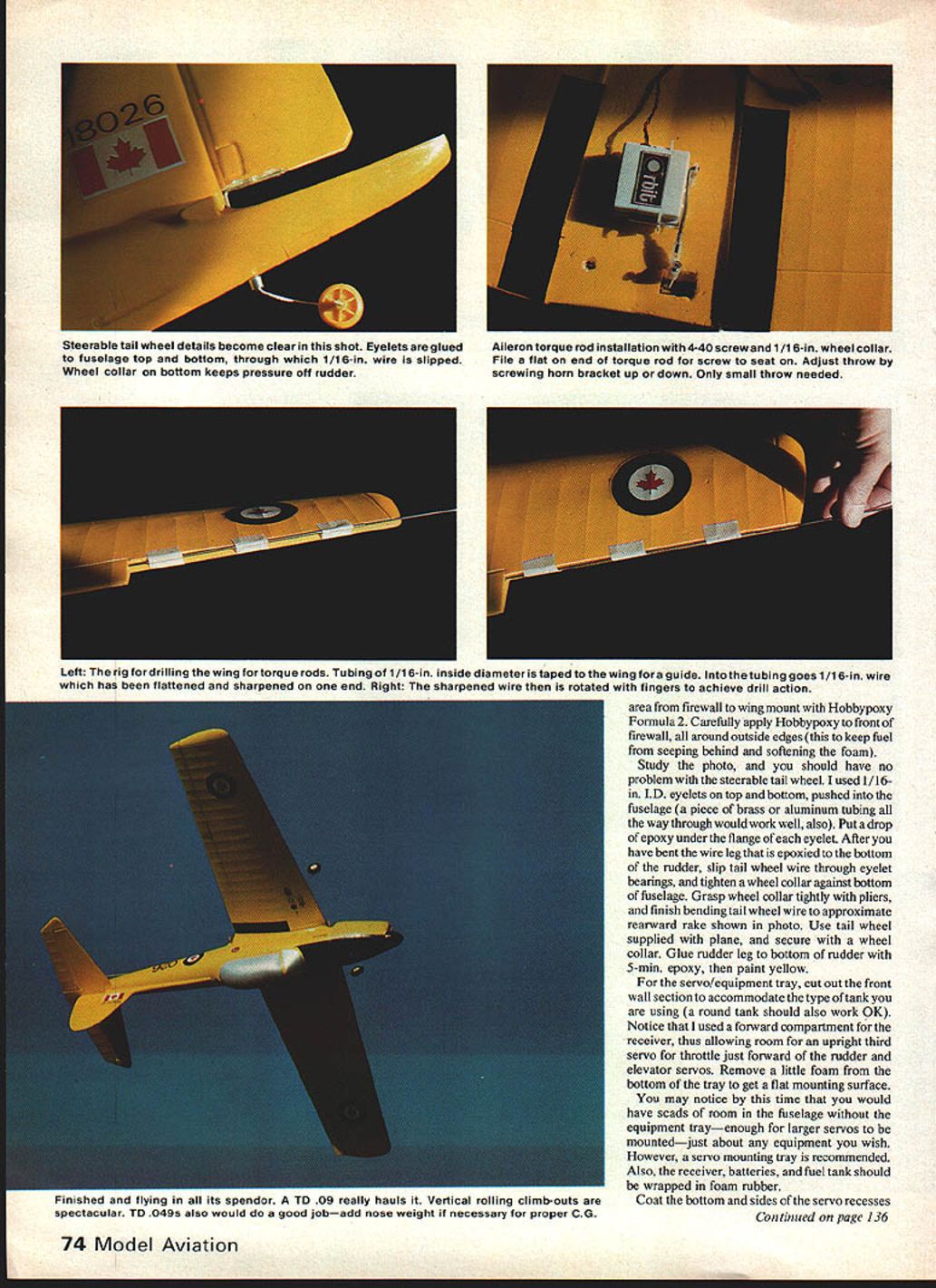
Tail wheel
- For a steerable tail wheel, use 1/16‑in. ID flanged eyelets top and bottom pushed into the fuselage. A length of brass or aluminum tubing through the fuselage also works.
- Put a drop of epoxy under the flange of each eyelet. Bend the tail-wheel wire leg and slip it through the eyelet bearings. Tighten a wheel collar against the bottom of the fuselage to retain the wheel.
- Grasp the wheel collar with pliers while finishing the bend to the approximate rearward rake. Glue the rudder lead wire to the rudder bottom with 5‑min epoxy and paint yellow as desired.
Drilling the wing for torque rods (aileron torsion rods)
- Tape a length of 1/16‑in. I.D. tubing to the wing to serve as a drilling guide from the aileron cutout to the center section (wing root).
- Flatten and sharpen the end of a 1/16‑in. music wire. Pass the wire through the tubing and rotate it between your fingers to “drill” through the foam. Start as close as possible to the top surface to align with the aileron hinge pivot point.
- Proceed slowly and patiently. If the wire bends and exits the wrong surface, re-angle the tubing and try again.
- Once the torque rods are in, use wheel collars at the base of the torque rods and install 4-40 x 3/8‑in. screws in place of the set screws. These screws double as adjustable-throw control arms.
- Bend the outer ends of the torque rods back at right angles (~1/2 in long). Let these arms slide freely inside a short piece of 1/16‑in. I.D. tubing epoxied to the inboard end of the aileron (after scraping a half-round depression for the tubing). This prevents binding and allows removal of the aileron for repair.
Cutting and hinging the ailerons
- Using a sharp blade, cut the ailerons free from the wings. Sand a bevel on the leading edge of the ailerons to permit 25°–30° downward deflection when taped at the top hinge line.
- Sand exposed foam with 220‑grit wet-or-dry and paint all exposed foam with Pactra Formula U.
- Use Mylar adhesive tape (Scotch brand) for tape hinges: pin the aileron in place, apply a full-length strip of tape with half on the aileron and half on the wing, fold the aileron back, apply a second strip to the leading edge, trim excess tape, and remove pins. The hinge will be gapless and efficient; motion may seem stiff initially, but only modest throw is needed.
- Slip the short tubing over the torque rod arm and epoxy it against the butt end of the aileron so the rod slides within the tubing as it rotates.
Servo placement and final wing work
- The aileron servo location depends on how the rudder and elevator servos fit above the equipment tray. Scrape a flat surface into the foam for servo mounting and coat it with epoxy to secure the servo mounting tape.
- Apply Scuff Guard strips to the underside of the wingtips for protection.
Fuel tank and cowl
- Slip the fuel tank in and position it all the way forward. Shape pickup tubing to a smooth curve from tank to engine. Route the breather line out the rear bottom of the cowl.
- Glow-plug access may be via a hole in the cowling or by leaving a Cox glo-head clip on the plug and passing the leads out the cowling bottom rear; leave bare wire ends for starter battery alligator clips.
- Pack foam rubber around the tank to absorb fuel/exhaust residue. A 250 mAh battery pack fits nicely in the space behind the tank.
Final mounting and fuel-proofing
- After epoxy curing, install blind nuts in the mount in the proper positions for the inverted engine. Verify engine screw alignment and tighten.
- Coat critical areas (mount, drilled holes) with Hot Stuff Super‑T where exposed to fuel.
- Fix the equipment tray firmly with white glue or tape. Install pushrods per the kit instructions after the stabilizer is glued in place. Be careful positioning the stabilizer the first time as the cowl can grab.
Balance and preflight
- The conversion is complete when the model balances no farther back than the point where the wing leading-edge sheeting meets the ribs. If not forward enough, add weight. For first flights, err slightly nose-heavy.
- The kit's electric instructions suggest a balance no more than 2 in. behind the wing leading edge — a safe starting point. You can move the CG rearward later for a more touchy response.
Flying impressions and tips
- Expect lively performance. Converted examples have weighed around 23 oz — light for the size and very responsive.
- On takeoff, be ready to apply right rudder immediately (less critical for hand launches). Expect a strong initial climb; you may need some down trim after launch.
- The Chipmunk handles quickly with little wind. Rolls require a touch of forward elevator near the inverted point. Inverted flight tends to roll out due to dihedral; hold inverted with aileron and rudder combination.
- Basic maneuvers (stall turn, Immelmann, Cuban eight, loop, split S, roll) are flown with little effort.
- Warning: do not take your eyes off the aircraft — it’s fast and not forgiving. This converted plane is not a beginner's trainer but a fine sport aerobat.
Editor’s note
If you like the idea of a gas-powered Chipmunk but prefer not to perform the conversion yourself, check MRC’s DeHavilland Chipmunk. It is ready-to-fly on three channels with an Enya .09TV engine and includes a four-channel aileron conversion kit.
Transcribed from original scans by AI. Minor OCR errors may remain.

