
The Coronel C-1 Transverse Wing: Experimental Aircraft
Photo captions
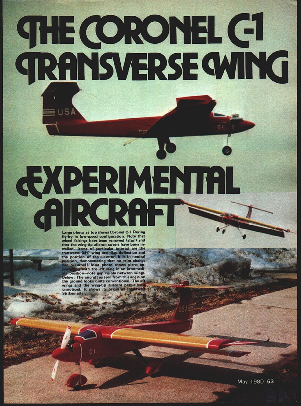
- Large photo: Coronel C-1 during a fly-by in low-speed configuration. Wheel fairings have been removed and the wing-tip aileron covers have been installed. Items of particular interest are the transverse (aft) wing and flap deflection, and the position of the elevator — it is in neutral position, demonstrating that no trim change has occurred.
- Inset photo: Plane approaching with the aft wing in an intermediate position — note the gap visible between wings.
- Ground view: From this angle the aircraft looks quite conventional. The aft wings and the wing-tip ailerons pass almost unnoticed. The aircraft shows its origin as a Midwest Strikemaster.
Overview
The Coronel C-1 Transverse Wing aircraft is a radio-controlled prototype built to flight-test a new concept in variable high-speed / high-lift airfoils. The concept is intended to create a new class of high-performance aircraft with short takeoff and landing capabilities. Potential applications range from supersonic transports and fighters to subsonic aircraft capable of operating from very limited fields.
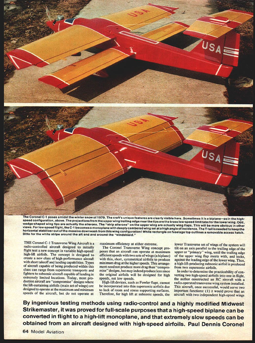
Most production aircraft are compromise designs: the main wing is designed to perform across the aircraft's speed range but is not optimal at either extreme. The Coronel Transverse Wing concept proposes using two sets of wings (a biplane arrangement) composed of thin, short, symmetrical airfoils optimized for high-speed, low-drag flight. For subsonic, high-lift flight the lower (transverse) wing tilts until the trailing edge of the primary wing flap meets and locks against the leading edge of the lower wing, effectively forming a high-lift monoplane airfoil from two supersonic airfoils.
Transverse wing concept details
- Thin supersonic airfoils are used for low-drag, high-speed performance.
- High-lift devices (e.g., Fowler flaps) cannot be incorporated into thin supersonic profiles. The solution is to reconfigure two high-speed airfoils in flight by tilting the lower wing to form a combined high-lift airfoil.
- The system must allow reliable locking and unlocking of the transverse wing in flight and permit large changes in lift without excessive trim changes.
Prototype development
Objectives
The radio-controlled prototype served two main purposes:
- To prove that two independent high-speed wings could be converted in flight into a high-lift monoplane.
- To demonstrate practical feasibility of the concept for patent and development purposes.
Much thought was put into the design of the Coronel Transverse Wing-equipped aircraft. By ingenious testing methods using radio control and a highly modified Midwest Strikemaster, it was proven for full-scale purposes that a high-speed biplane can be converted in flight to a high-lift monoplane, and that extremely slow speeds can be achieved from aircraft designed with high-speed airfoils.
Design parameters
After researching available kits and components, the following design parameters were adopted:
- Use a powerplant in the .40 cu. in. range (provides sufficient power and fuselage space for the wing-tilt mechanism).
- Use a high-wing monoplane as the basic design to allow placement of the secondary (transverse) wing below and aft of the primary wing. Adding the second set of wings behind the original would change the center of gravity and require lengthening the fuselage.
- Select the finest components available to minimize the probability of failure.
- Start with a well-designed kit and redesign it to meet the project specifications to reduce construction time.
Kit selection and major components
- The Midwest Strikemaster kit was chosen for conversion; designer Jim Newman of Midwest provided plans and assistance.
- Radio: Kraft-manufactured Tower Hobbies 6-channel transmitter and receiver with proportional 5th channel.
- Servos: Four KPS 15 servos for primary controls and a high-torque 180° KPS 16 servo (purchased from Kraft) to operate the transverse wing tilting system.
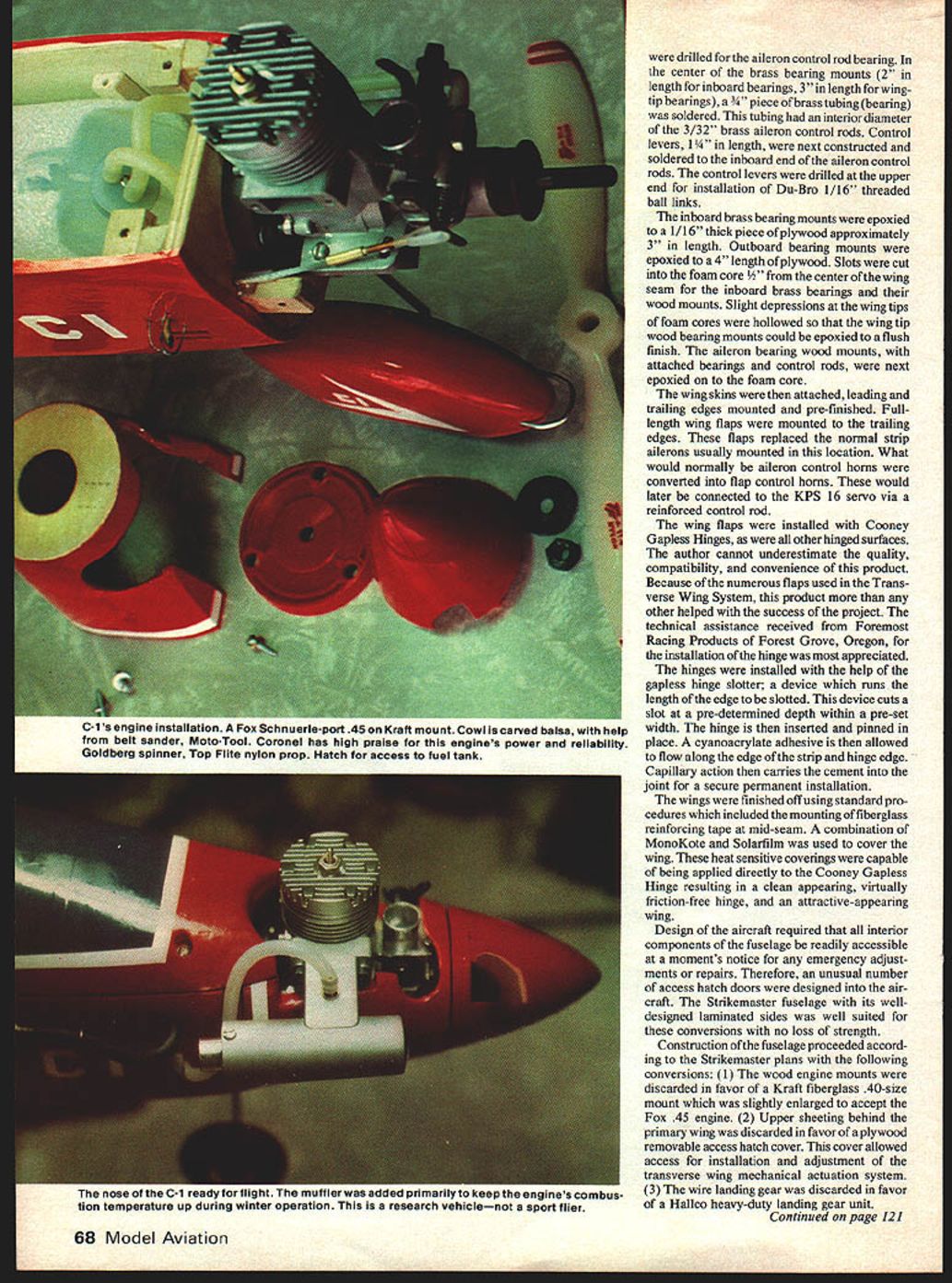
- Engine: Fox .45 cu. in. Schnuerle-ported engine (approximately 1 hp). A muffler was used during winter testing to help control combustion temperature and prevent glow plug cooling.
- Pilot and support: Pilot John Lusk (president, Madison Area Radio Control Society) and assistant Ralph Bethke.
Construction
Primary (upper) wing
- Foam wing cores were shortened by 3 in. at each wing tip (6 in. total).
- The bottom curved surface of the foam cores was sanded flat. A slot for the aileron control rods was routed into the bottom with a 1/2" router bit to a depth of 3/4".
- Both wing cores were joined; a square hole was cut in the center bottom for the aileron control servo.
- Metal bearings were constructed from 1/2"-wide brass strips and soldered with 3/8" brass tubing to accept 3/32" brass aileron control rods. Inboard brass bearing mounts were 2" long; wing-tip mounts were 3" long.
- Control levers (1-1/4" long) were soldered to the inboard end of the aileron control rods and drilled to accept Du-Bro 1/16" threaded ball links.
- Inboard brass bearing mounts were epoxied to 1/16" plywood pieces (approx. 3" long); outboard mounts were epoxied to 4" lengths of plywood.
- Slots were cut into the foam cores 5/8" from the center seam for the inboard bearings; small depressions at the tips allowed the outboard mounts to be epoxied flush.
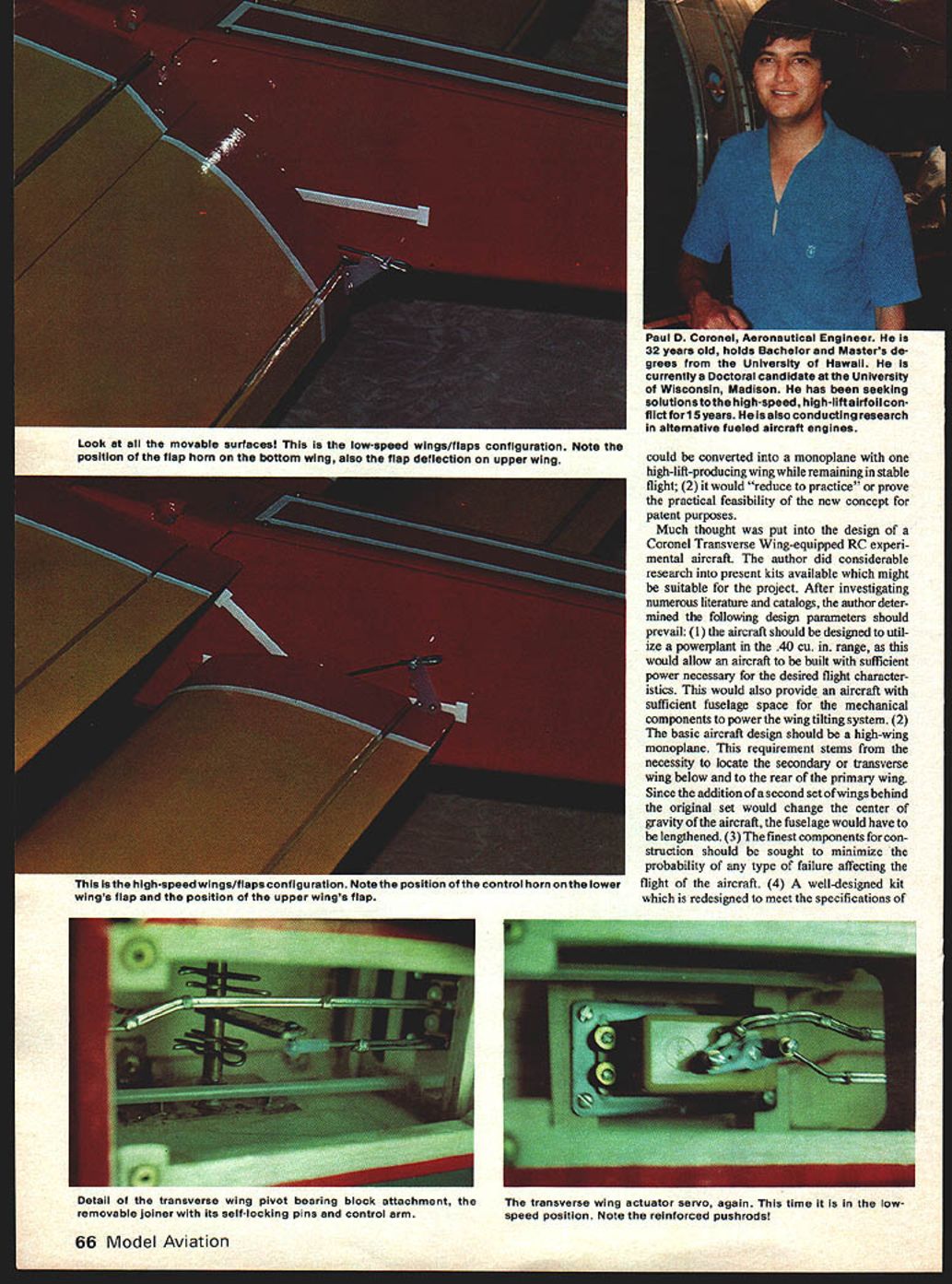
- Wing skins, leading and trailing edges were mounted and prefinished. Full-length wing flaps replaced the usual strip ailerons; what would normally be aileron control horns were converted into flap control horns and later connected to the KPS 16 servo via a reinforced control rod.
Hinges, coverings and finishes
- Cooney Gapless Hinges were used on all hinged surfaces. The gapless hinge slotter ensured uniform hinge slots; cyanoacrylate adhesive provided a secure installation.
- Fiberglass reinforcing tape was used at the mid-seam.
- Wing coverings used Monokote and Solarfilm, applied directly over the gapless hinges to produce a clean, low-friction hinge and attractive finish.
- The author greatly appreciated technical assistance from Foremost Racing Products (Forest Grove, Oregon) for hinge installation.
Aileron modification
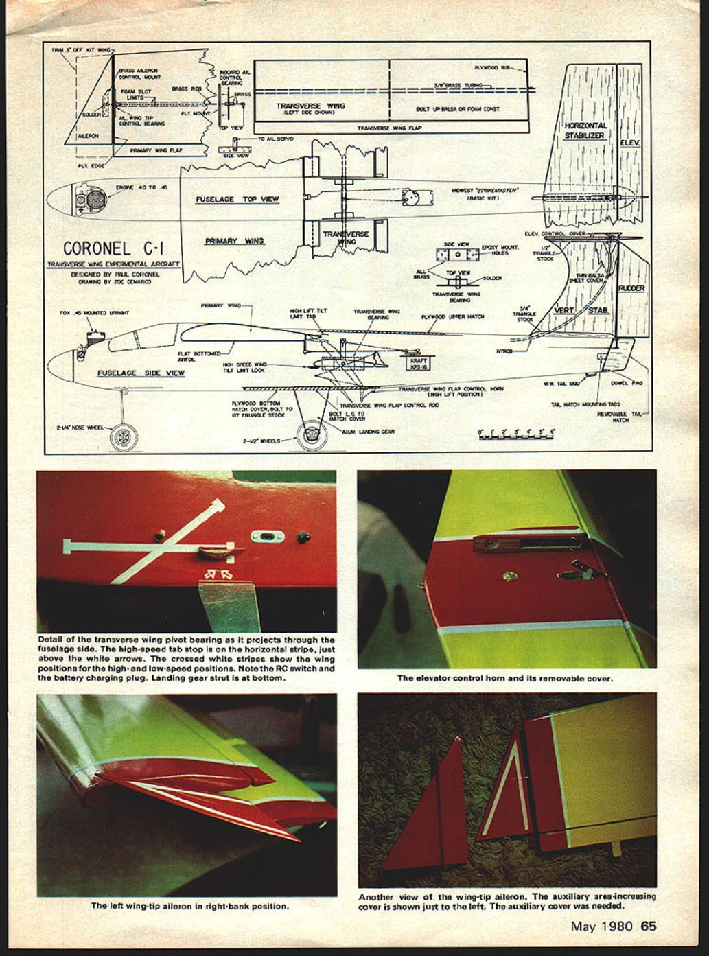
- Special wing-tip aileron covers were later added (two sheets of balsa glued over existing ailerons), increasing aileron area by about 33% to improve lateral stability when the transverse wings were fully tilted.
Fuselage modifications
Conversions to the Strikemaster fuselage included:
- Replacing the wood engine mount with a Kraft fiberglass .40-size mount, slightly enlarged to accept the Fox .45 engine.
- Removing upper sheeting behind the primary wing and installing a plywood removable access hatch for the transverse wing actuation system.
- Replacing the wire landing gear with a Hallco heavy-duty landing gear unit bolted to a plywood access hatch (approx. 10" long). This hatch and gear could be removed as a unit to allow access for adjustments.
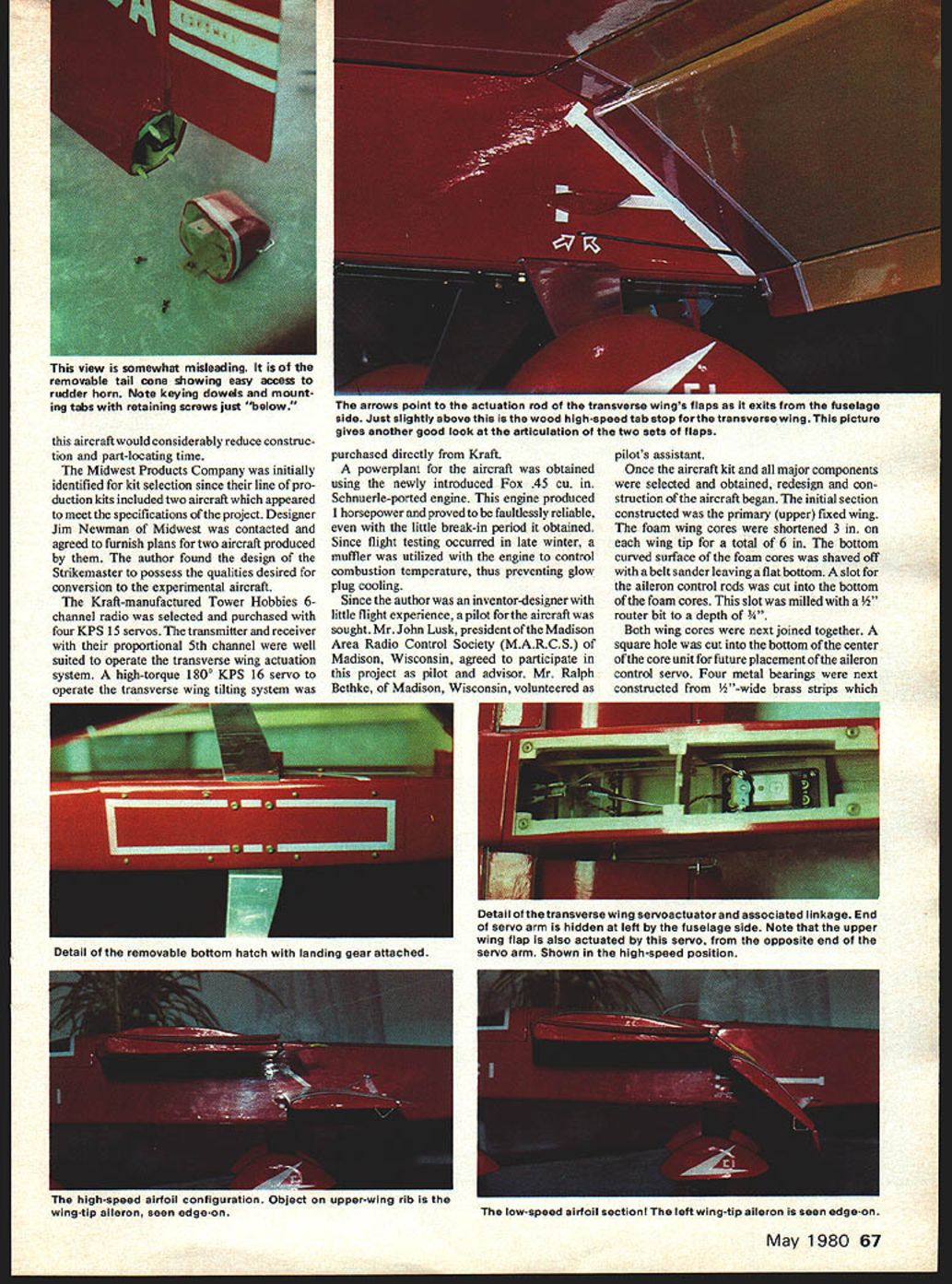
- Extending the tail by approximately 3" using a removable tail cone for unobstructed access to the rudder control horn.
- Converting the stabilizer to a T-tail configuration to avoid large changes in airflow at the lower tail with transverse wing actuation.
Elevator and rudder controls
- Elevator control: Nyrod flexible pushrod routed through a curved slot cut through the vertical stabilizer. The Nyrod was epoxied in place between front and rear sections, then the stabilizer skins were applied.
- Horizontal stabilizer mounted on top of the vertical stabilizer with 1/8" triangular fillets. A removable access hatch covered the elevator control horn and allowed adjustment of elevator tilt limits.
- Care was taken to achieve zero incidence between stabilizer and primary wing. Elevator and rudder surfaces were increased by 20%.
Transverse wing mechanism
- Precise alignment was critical. Fuselage squareness was verified, and the leading edges of the transverse wings were taped to the trailing edges of the primary wing flaps for initial alignment.
- Maximum transverse wing angle (45°) was marked on the fuselage. Holes were drilled and the main support bearings epoxied to the inner fuselage walls.
- High-speed position tilt limits: Aerodynamically carved hardwood blocks attached to both sides of the fuselage provided a felt-covered locking surface for the inboard leading edge of the transverse wing. The KPS 16 servo's slight over-rotation beyond its 180° limit prevented unlocking without radio command.
- High-lift position tilt limits: Felt-covered, reinforced brass limit tabs (1-1/2" x 1/2") epoxied to the rear of the primary wing flaps near the tips limited transverse wing tilt when in the maximum high-lift position.
Final finishing and identification
- Removable hatches and covers were marked with a white strip of Goldberg multi-stripe tape.
- A red/yellow color scheme was chosen for photographic contrast. Maximum and minimum wing tilt angles were taped to the fuselage sides for photographic reference.
- U.S.A. markings were applied to emphasize an American effort.
Flight testing
- Date: March 1, 1979. Location: flight field near Madison, Wisconsin. Conditions: some snow on the ground, air temperature ~40°F, 8-mph NE wind.
- First attempt: aborted because the aircraft was tail-heavy. Nose ballast (lead) was added.
- Subsequent flights: aircraft lifted off cleanly and responded well to wing-tip ailerons. Altitude was gained and the transverse wings were unlocked and partially tilted by the assistant. Partial tilt produced a reduction in speed and a slight nose-down attitude.
- Full actuation of the wing system initially produced a tendency to roll to the left. The aileron covers (increasing aileron area by ~33%) improved lateral stability.
- After modifications the pilot achieved sustained level flight with the transverse wings in full tilt. Further flights showed left turns could be corrected without difficulty. The aircraft was recovered without damage.
Conclusions
- The transverse wing concept is feasible: a high-speed biplane can be converted in flight to a high-lift producing monoplane.
- Extremely low speeds can be obtained from an aircraft designed with high-speed airfoils using the Coronel Transverse Wing concept.
FLY SAFELY!
— Paul Dennis Coronel
Transcribed from original scans by AI. Minor OCR errors may remain.

