
Coronet 150
My strategy was straightforward enough. In updating Scientific's popular 1941 Coronet kit design by means of a 50% enlargement and the addition of RC-assist, I expected to produce nothing more than a cute-looking sport design outfitted with a four-stroke engine. What emerged instead was totally unexpected. The Coronet 150 goes well beyond sport flying. Not only does this SAM-legal model have strong competition potential, it's quite simply the finest-flying Old-Timer yet to come out of my workshop. To say that I was astounded at unleashing all that prowess is an understatement.
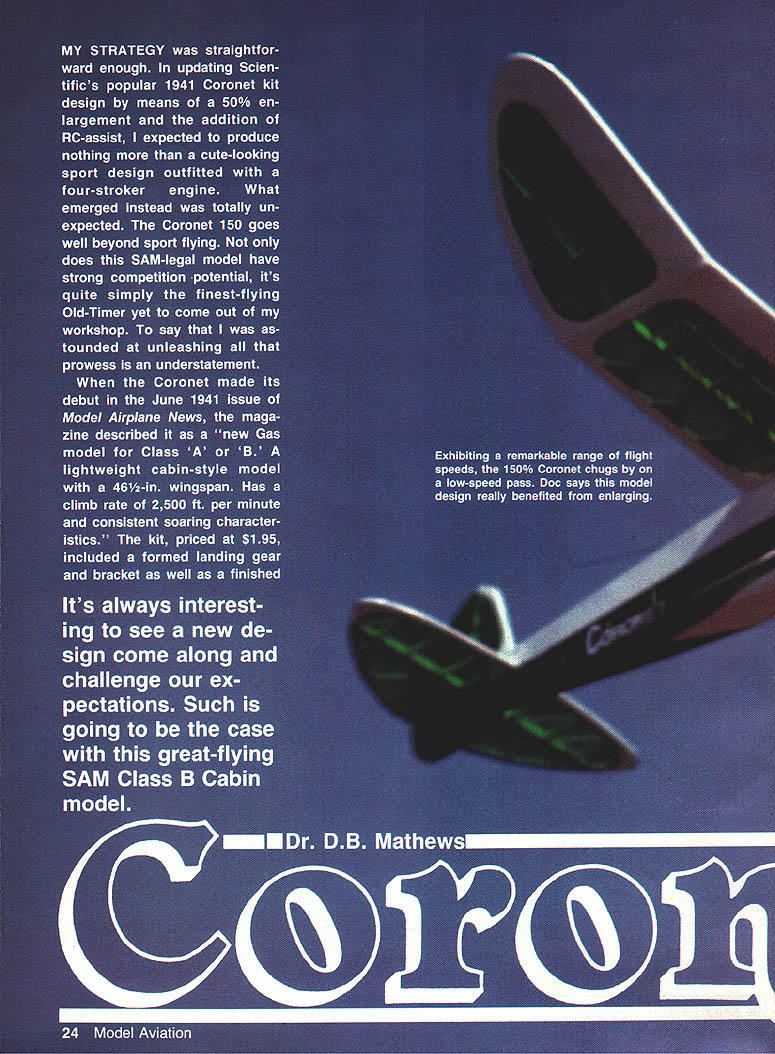
When the Coronet made its debut in the June 1941 issue of Model Airplane News, the magazine described it as a "new Gas model for Class 'A' or 'B.' A lightweight cabin-style model with a 46½-in. wingspan. Has a climb rate of 2,500 ft. per minute and consistent soaring characteristics." The kit, priced at $1.95, included a formed landing gear and bracket.
"It's always interesting to see a new design come along and challenge our expectations. Such is going to be the case with this great-flying SAM Class B Cabin model."
- Dr. D.B. Mathews
Back in those days, kit manufacturers usually did not credit the designers unless a model was nationally known. The Coronet was no exception. But whoever designed this model gave it considerable aesthetic appeal, and the Coronet kit was a very popular one for many years.
I tried to build a Coronet during World War II with poor results. Wartime shortages made it impossible to obtain suitable balsa, and my kit had substitutions—an unspecified hardwood (which may have been pine) for strip and some sort of paper for the ribs—that were not very satisfactory. I never completed the model, and until this project tilted it around 180 degrees, my feeling toward the Coronet had remained rather negative.
Since in designing the Coronet 150 all outlines and dimensions were machine-enlarged from the original kit plans, the model is totally SAM-legal. SAM rules allow four-cycle engines 60% of the displacement of two-cycle ones for competition. On that basis, a .40 four-cycle engine is considered the equivalent of a .24 two-cycle. That, in my experience, definitely favors the four-stroker. With a Schnuerle-ported .25 two-stroke engine our Coronet is a fine flier and climbs rather briskly, but with the four-stroke .40 she will leap up as straight as an arrow! In the hands of an expert competition flier, this engine-model combination could well be an eye-opener to folks who are convinced that a Playboy Cabin or a Clipper is the only way to go in B Cabin.
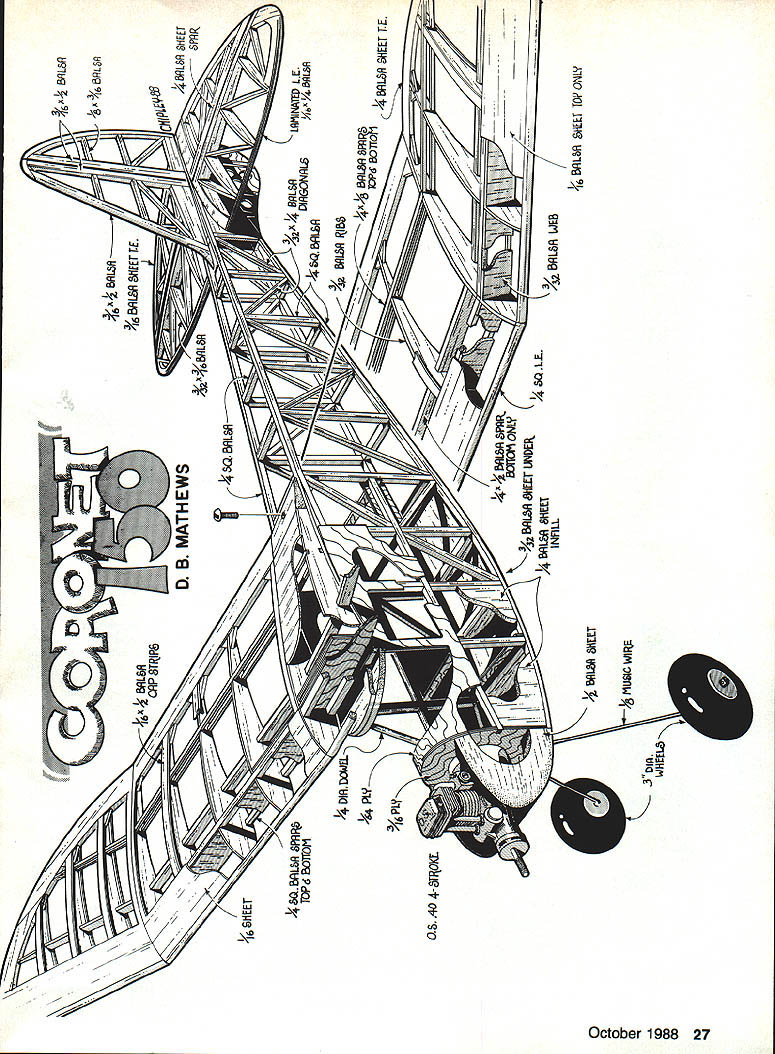
Apart from the 50% enlargement and adding the RC assist, I've made a few other slight changes in the original design, primarily in the wing. The original had a single main spar, cap-stripped ribs, and sheeting only on the top—a combination of features which, when enlarged, produced a very wiggly, unstable structure. My solution was to add top and bottom spars and shear webs. I then added triangular gussets to the trailing edge to correct warping.
Although no fuselage cross braces were used in the original design, our model employs them for rather obvious reasons. A hidden elevator control horn looks neat but is certainly not required. Likewise it's not mandatory to use the wing hold-down method shown in the plans; if you prefer a more pragmatic approach, it won't affect the flying characteristics of your model.
Equipped with the O.S. four-stroke engine, our model balanced without any ballast. If you're planning to use a two-cycle unit instead, be prepared to compensate by adding some nose weight.
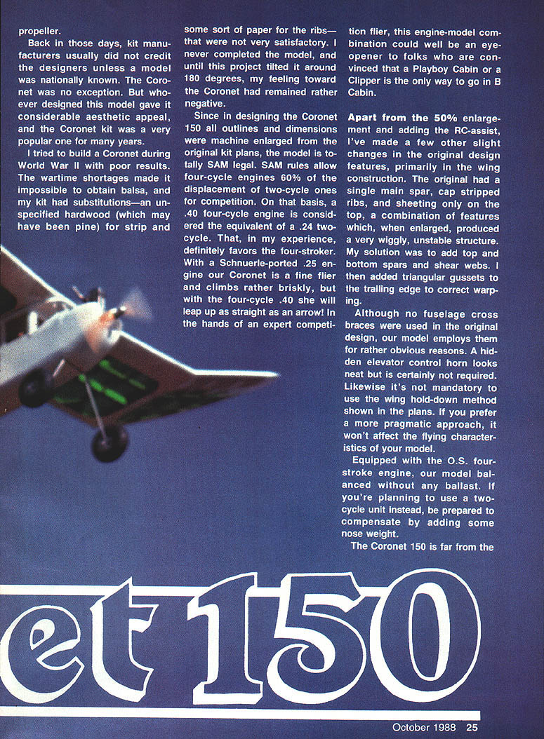
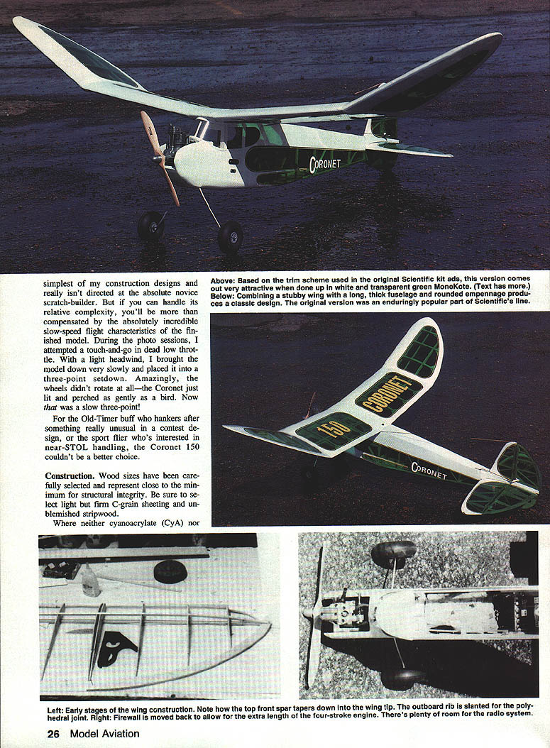
The Coronet 150 is far from the simplest of my construction designs and really isn't directed at the absolute novice scratch-builder. But if you can handle its relative complexity, you'll be more than compensated by the absolutely incredible slow-speed flight characteristics of the finished model. During the photo sessions I attempted a touch-and-go in dead-low throttle. With a light headwind, I brought the model down very slowly and placed it into a three-point setdown. Amazingly, the wheels didn't rotate at all — the Coronet just alit and perched as gently as a bird. Now that was a slow three-point!
For the Old-Timer buff who hankers after something really unusual in a contest design, or the sport flier who's interested in near-STOL handling, the Coronet 150 couldn't be a better choice.
Construction
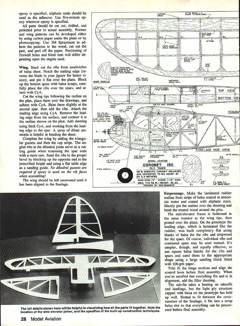
Wood sizes have been carefully selected and represent close to the minimum for structural integrity. Be sure to select light but firm C-grain sheeting and unblemished stripwood.
Adhesives and materials:
- Where neither cyanoacrylate (CyA) nor epoxy is specified, use an aliphatic resin as the adhesive.
- Use five-minute epoxy wherever epoxy is specified.
- Parts should be cut out, drilled, and pre-kitted prior to actual assembly.
Former/plan patterns:
- Former wing patterns can be developed either by using carbon paper under the plans or by photocopying.
- Use 3M Spraymount to adhere patterns to the wood, cut out parts, and peel off the paper.
- Positioning of firewall holes and blind nuts will differ depending upon the engine used.
General build notes:
- Stack-cut the wing ribs and sandwich balsa sheet where indicated.
- Notch the trailing edge and use a reverse-blade jigsaw for better visibility when cutting; pin the assembly flat over the plans.
- Block up the bottom spars on balsa scraps and carefully place ribs over the spars; tack with CyA.
- If epoxy is used, dihedral gussets are not required.
- If rib faces are assembled with CyA, leave them uncovered until the wing has been aligned with the fuselage.
Wing
- Stack and cut ribs; sandwich balsa sheet where called for.
- Notch the trailing edge; a reverse-blade jigsaw gives better visibility. Pin the assembly flat over the plans.
- Cut wing tips following the outline on the plan, place over the drawings and adhere with CyA.
- Shim slightly at the second spar and add the ribs for the second spar.
- Attach the leading edge using CyA, then remove the leading-edge surface waste and contour to the outline shown on the plan.
- Add sheeting using thick CyA; working the leading-edge spar, spray dilute ammonia on the sheet to help bending the sheet.
- Complete the wing by adding triangular gussets, cap strips and glued rib gussets at the dihedral joints; these also serve as a cutting guide when trimming spar ends with a razor saw.
- Sand ribs to the proper bevel by blocking up the opposite end to the prescribed height and using the flat table edge as a sanding guide.
Notes:
- The triangular gussets at the trailing edge correct warping on the enlarged structure.
- If epoxy is used for major joints, dihedral gussets are unnecessary.
- Leave rib faces uncovered until final wing-to-fuselage alignment if they were assembled with CyA.
Empennage
- Make the laminated rudder outline strips from balsa soaked in ammonia water and coated with aliphatic resin. Pin the outline over the drawing and bend the treated wood around the pins.
- The stab/elevator frame is fashioned in the same manner. Pin the wing tips and empennage parts over the plans as required.
- On the prototype the leading edge was laminated like the rudder and built completely flat using blanks of balsa for ribs and stripwood for spars. Individual ribs and contoured spars may be used instead, but using square balsa blanks and sanding to shape is simpler and equally effective.
- Use a large sanding block fitted with 100-grit paper to contour ribs and spars.
- Trial-fit the hinge sections and align the control horn before final assembly. When satisfied with fit and alignment, add the filler sheeting.
- The sub-fin takes a beating on takeoffs and landings; the light-ply structure capped with balsa on the prototype has held up well. It is slotted to fit between the fuselage crossmember and fits into a scrap balsa slot so that everything can be precovered before final assembly.
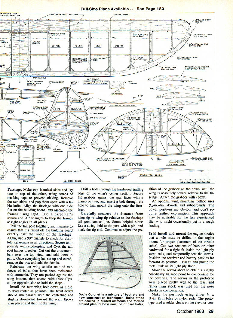
Fuselage
- Make two identical sides; lay one on top of the other and use scraps of masking tape to prevent sticking. Remove the two sides and separate them carefully with a table knife.
- Align one fuselage side flat on the building board and assemble the frames using CyA. Use a carpenter's square and 90° triangles to keep the frames at right angles in all planes.
- Pull the tail post together and measure to ensure it is raised off the building board exactly half the width of the fuselage. Use a 90° triangle to check for absolute squareness in all directions. Secure temporarily with clothespins and CyA to hold tail post halves together.
- Cut out crossmembers over the top view and add them in pairs. Once everything has set up, remove the box and add the details.
- Fabricate the wing saddle unit from two sheets of balsa moistened with ammonia. Push them against the wing bottom and coat the opposite side with thick CyA to hold the shape.
- Install the rear wing hold-down as close to dead center as possible. The front dowel should run parallel with the centerline and slightly downward toward the rear. Epoxy it in place, then fit the wing.
- Drill a hole through the hardwood trailing edge of the wing's center section. Secure the grabber against the spar faces with clamps and insert a bolt through the hole to trial-mount the wing onto the fuselage.
- Carefully measure the distance from wing tip to wing tip relative to the fuselage tail-post centerline. Use a string held to the post with a pin and mark the tip end. Adjust the grabber on the dowel until the wing is absolutely square relative to the fuselage, then attach the grabber with epoxy.
Optional wing mounting:
- An alternative is to use 5/16-in.-dia. dowels and rubber bands for wing mounting. This method is straightforward and may be advisable for the less experienced flier who might occasionally have a rough landing.
Engine, radio and balance:
- Trial-install and mount the engine (a hole must be drilled in the engine mount for proper placement of the throttle cable).
- Cut two sections of bass or other hardwood for a tight fit inside the light-ply servo rails, and temporarily seat the servos.
- Position the receiver and battery pack as far forward as possible. Trial-fit and plumb the metal tank onto its light-ply floor.
- Move the servos to obtain a slightly nose-heavy balance point to compensate for the covering. The prototype used servos placed fairly far aft and rather firm stock for the nose cheeks for compensation.
- Make pushrods using either 1/4 x 1/16-in. firm balsa or nylon rods. The prototype used a soldered clevis on the elevator control horn and an EZ connector on the servo.
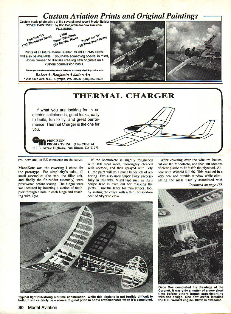
Covering and finishing
- MonoKote was used on the prototype. For simplicity, all small assemblies (stab, filler unit, and finally the fin-rudder assembly) were precovered before seating.
- Secure hinges by inserting a section of toothpick through a hole in each hinge and attaching with CyA.
- If the MonoKote is slightly roughened with 400 steel wool, thoroughly cleaned with acetone, and then sprayed with Poly U or Super Poxy, paint will adhere much better.
- Vinyl tape such as Sig's Stripe Rite is excellent for masking joints and for trim stripes. Seal the tape edges with a thin brushed-on coat of Skybrite clear.
- After covering over the window frames, cut out the MonoKote and then cut sections of clear plastic to fit inside the plywood. Adhere with Windex RC 56 for neat, durable windows and to eliminate the usual mess.
Flying
- When balanced at the point shown on the plans and with control deflections set as indicated, the Coronet 150 will literally jump off the ground at full throttle—so much so that I recommend gentle applications of throttle on the first few flights. Just point her nose into the wind and gently advance the throttle until she's airborne. No control input should be needed.
- Climbout is purely a function of power: more throttle produces a steeper climb. The faster she flies the touchier she is. For casual sport flying, leave the engine at half throttle. For competition, open her up.
- The Coronet 150 is remarkably thermal-ready. It tends to ride very light lift well. Whether the power is on or off, the model's combination of extremely slow flight speed with exceptional stability gives it a definite edge. In strong lift this airplane is quite capable of beating more streamlined sisters.
Power, stability, and versatility: with the Coronet 150 you can have it all. Reduce the power for gentle, enjoyable sport flying; pull out all the stops and take advantage of her highly competitive thermaling ability. This airplane marries the best of both worlds, and either way you can't lose!
Transcribed from original scans by AI. Minor OCR errors may remain.

