
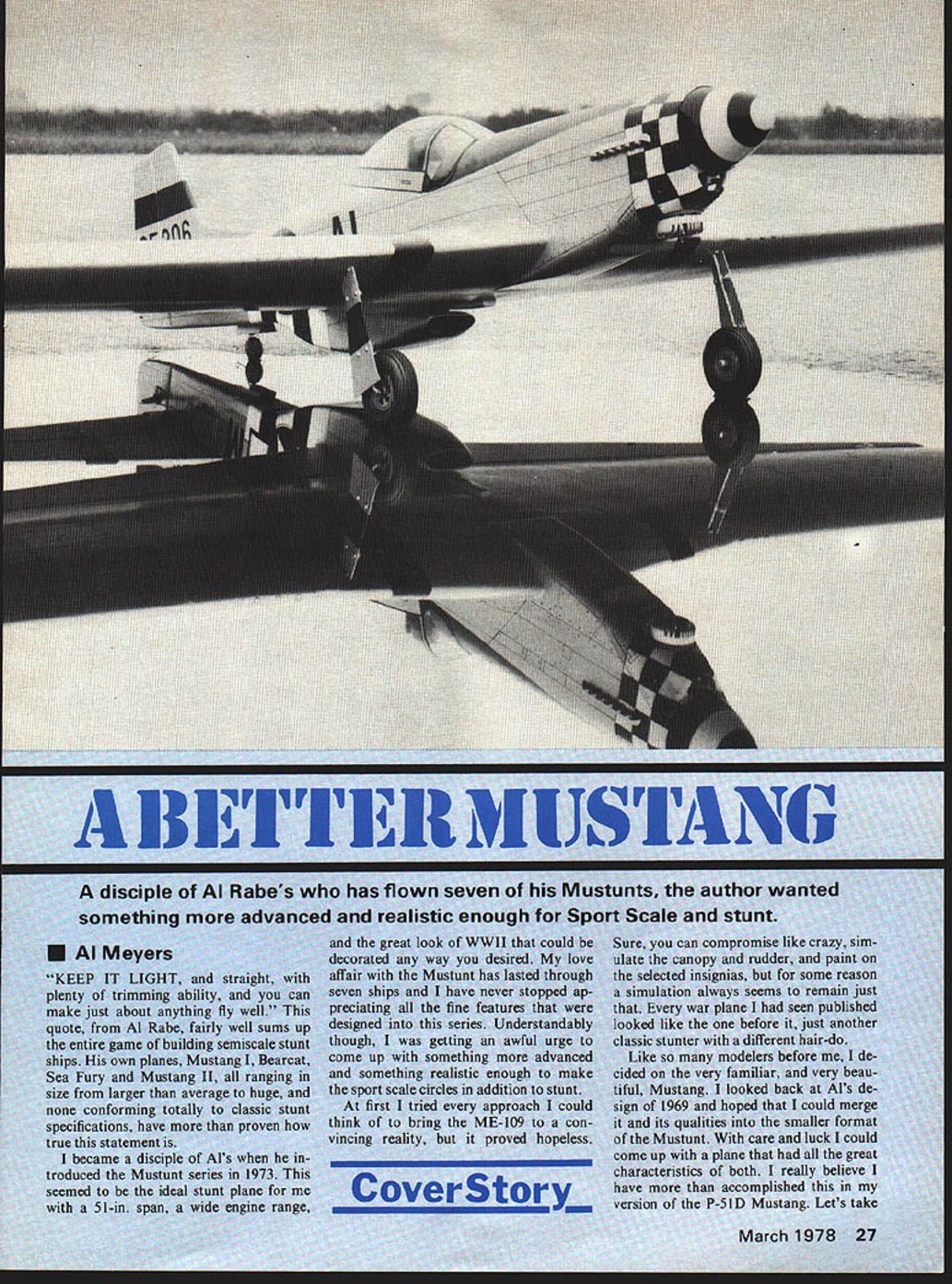

Cover Story: A Better Mustang
A disciple of Al Rabe's who has flown seven of his Mustunts, the author wanted something more advanced and realistic enough for Sport Scale and stunt.
Al Meyers
"KEEP IT LIGHT, and straight, with plenty of trimming ability, and you can make just about anything fly well." This quote, from Al Rabe, fairly well sums up the entire game of building semiscale stunt ships. His own planes, Mustang I, Bearcat, Sea Fury and Mustang II, all ranging in size from larger than average to huge, and none conforming totally to classic stunt specifications, have more than proven how true this statement is.
I became a disciple of Al's when he introduced the Mustunt series in 1973. This seemed to be the ideal stunt plane for me with a 51-in. span, a wide engine range, and the great look of WWII that could be decorated any way you desired. My love affair with the Mustang has lasted through seven ships and I have never stopped appreciating all the fine features that were designed into this series. Understandably though, I was getting an awful urge to come up with something more advanced and something realistic enough to make the sport scale circles in addition to stunt.
At first I tried every approach I could think of to bring the ME-109 to a convincing reality, but it proved hopeless.
Sure, you can compromise like crazy, simulate the canopy and rudder, and paint on the selected insignias, but for some reason a simulation always seems to remain just that. Every war plane I had seen published looked like the one before it, just another classic stunter with a different hair-do.
Like so many modelers before me, I decided on the very familiar, and very beautiful, Mustang. I looked back at Al's design of 1969 and hoped that I could merge it and its qualities into the smaller format of the Mustunt. With care and luck I could come up with a plane that had all the great characteristics of both. I really believe I have more than accomplished this in my version of the P-51D Mustang. Let's take A look at some major features of the two planes will show the importance of the two designs superimposed.
Mustang I 1 Nearly scale profile 2 working rudder 3 wing dihedral 4 fine steady penetration
Mustunt III 1 New concept stunt design 2 new thick airfoil 3 compact size 4 external control horns 5 unlimited trimming ability 6 capable engines .35–.46 7 moderate use of molded parts
I really rushed the first plane, always having the feeling that it just might come up short of expectations. As a result, the finished showpiece could have its performance compromised. Something else that flew steadily on rails could stunt with much more precision; a pilot who could handle it could telegraph the ship. So, realizing the existing potential, a new ship was started immediately. Minor profile corrections were made and further scale appearance modifications are contained in the published plans; the ship can be made scale-like if you choose.
What we have are very real pluses:
- Moderate size — a careful builder could easily equip the ship with a .35-size engine. Ships built with a .46 proved completely overpowered; a number of .40 engines could be dropped to .30 with good results.
FULL-SIZE PLANS AVAILABLE — SEE PAGE 104
Wing Jig
Almost any jig is based on the use of metal tubes. After searching around some weeks I failed to turn up anything satisfactory until I struck a practical tube available today. Fiberglass arrow shafts have almost no distortion, are practically indestructible, and are easily cleaned and waxed. The entire jig can be stored in a three-foot kit box.
The jig has four stanchions; bases are 1/4-in. ply, measure 4 x 6, tops 3-in. centers. Two square notches and 5/16-in. side slots slanting upward act as hooks for rubber bands. Naturally, to insure a perfectly matched set, the stanchion boards should be tacked together. Saw cuts can be made though the piece — arrow shafts come 32 inches long. To create a jig length of 65 inches it is necessary to connect centers by slipping over metal tubes about three inches long. Matching metal tubes slipped into the tip ends of the arrow shafts will give the ability to accurately bore-sight alignment of the wing throughout the entire construction.
When setting up the jig, usually locate the inner stanchions at the third and fourth bay. The center must not go out so far as to lose adequate clearance at the trailing edge spar. Outer stanchions go outside the wing just beyond the tip rib. After ribs are slipped approximately into position...
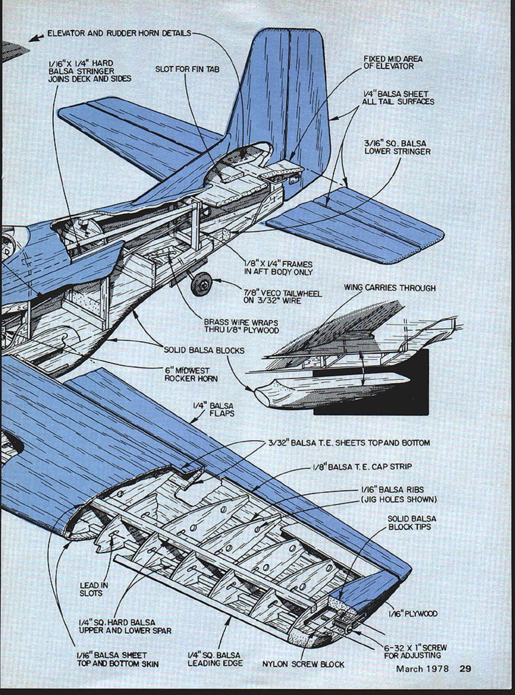
ELEVATOR AND RUDDER HORN DETAILS
- 1/16" x 1/4" hard balsa stringer joins deck and sides
- Slot for fin tab
- Fixed mid area of elevator
- 1/4" balsa sheet all tail surfaces
- 3/16" sq. balsa lower stringer
- 1/8" x 1/4" frames in aft body only
- 7/8" Veco tailwheel on 3/32" wire
- Brass wire wraps thru 1/8" plywood
- Solid balsa blocks
- 6" Midwest rocker horn
- 1/4" balsa flaps
- Wing carries through
- 3/32" balsa T.E. sheets top and bottom
- 1/8" balsa T.E. cap strip
- 1/16" balsa ribs (jig holes shown)
- Solid balsa block tips
- 1/16" plywood
- 6-32 x 1" screw for adjusting
- Nylon screw block
- Lead-in slots
- 1/4" sq. hard balsa upper and lower spar
- 1/16" balsa sheet top and bottom skin
- 1/4" sq. balsa leading edge
A look at some of the major features of these two planes and see why it was imperative that the two designs be superimposed:
Mustang I: 1) Nearly scale profile, 2) working rudder, 3) wing dihedral, 4) fine, steady penetration.
Mustang III: 1) New concept in stunt design, 2) new thick airfoil, 3) compact size, 4) external control horns, 5) unlimited trimming ability, 6) capable of engines from .35 to .46, 7) moderate use of molded parts.
I really rushed the first plane, always having a feeling that it just might not come up to expectations. As a result, it was not at all the finished show piece it could have been, but its performance was something else. It flew as steadily as if it were on rails, and could stunt with as much precision as the guy on the handle could telegraph into it. So, realizing the existing potential, a new ship was started immediately with only minor profile correction being made to further the scale appearance. The published plans have even greater profile modifications contained in them so that your ship can be as scale-like as you choose to make it.
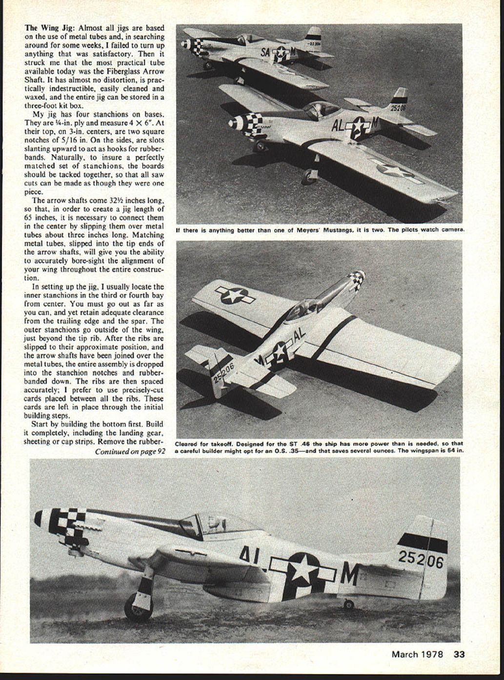
What we have here is a very real P-51 in a moderate size that a careful builder could easily hold to the .35-size engine. My ships were built with the ST46 in mind and proved to be completely overpowered. It was only natural then to scout up some ST40 engines so that they could be dropped to .40-size engines.
Wing Jig
Almost all jigs are based on the use of metal tubes. Searching around for some weeks failed to turn up anything satisfactory until I struck a practical tube available today. Fiberglass arrow shafts have almost no distortion, are practically indestructible and are easily cleaned and waxed. The entire jig can be stored in a three-foot kit box.
The jig has four stanchions. Bases are 1/4-in. ply, measure 4 x 6; tops, 3-in. centers; two square notches, 5/16 in. sides. Slots slanting upward act as hooks for rubber bands. Naturally, to insure a perfectly matched set of stanchions the boards should be tacked together. Saw cuts can be made through the pieces.
Arrow shafts come 32 inches long; order three to create a jig length of 65 inches. It is necessary to connect at the center by slipping over metal tubes about three inches long. Matching metal tubes slipped on the tip ends of the arrow shafts will give the ability to accurately boresight the alignment of the wing throughout the entire construction.
In setting up the jig, usually locate the inner stanchions at the third and fourth bay. The center must go out far enough to yet retain adequate clearance for the trailing edge spar; outer stanchions go outside the wing just beyond the tip rib. After the ribs are slipped approximately in place, proceed with locating and gluing the spars and trailing edge. Right into the same mount, but the plane flies with such ease that even the .40 is more than enough power. My next Mustang will certainly be aimed at the O.S.35, where three ounces will be saved in engine weight alone, along with smaller tank, and so on.
Construction is as simple as good building techniques will permit. The wing dihedral is about the only area where the construction gets moderately involved. This cannot be circumvented as there is no other way that roll balance in a low-winged stunt ship can be controlled.
The Ribs: Ribs for the wing are stack shaped in the usual manner, between a root and tip template. When making ribs in this manner, the question always arises whether or not to remove the tapered edge left on the rib. If you are sheeting fully, the taper creates no problem, but I have yet to put a good flat cap strip on the edge of a sharp 1/16-in. rib. Even if you put it on straight the chances are that as the glue dries and cures it will pull the cap strip crooked. Let me make this suggestion for removing the taper.
While the ribs are still tightly sandwiched between the templates, color the entire assembly with a pad saturated with powdered colored chalk. Use a minimum of chalk and rub it in thoroughly to avoid any unwanted spill. Now, when the ribs are separated, the tapered edge should be well defined and easy to sand away accurately. By doing this you will definitely reduce the thickness of your airfoil, so you may want to make your templates about 1/8 in. oversize. A little change in profile appearance will also take place, but should not be of any great consequence. You will have to decide for yourself. I have never removed the tapered edge, but do know of those who did using this method with satisfactory results. Do not remove the taper from the bird's mouth or trailing edge of the rib.
The Wing: You may build your Mustang wing with equal panels for a maximum 54-in. span, or you may respace the ribs to shorten the outboard panel by one inch. At the full 54-in. span you should start with 1 1/2 oz. of tip weight. With the span reduced to 53 inches, your first flight could be flown with one ounce. In either case, make it adjustable. It's also a good idea to weigh your adjustable leadout mechanism before installation, so that the equal of its weight can also be added to the outboard tip. These suggested weights should get you safely through your first test flights.
The wing itself is of simple D-tube design, and I don't believe needs a step by step description of construction. It is, however, a tapered fully symmetrical wing, requiring one inch of dihedral, and unless you have your own good methods for building a wing of this type, I would suggest that you spend a little time and about five dollars to construct a very simple, yet very efficient wing jig.
The Wing Jig
Almost all jigs are based on the use of metal tubes and, in searching around for some weeks, I failed to turn up anything that was satisfactory. Then it struck me that the most practical tube available today was the Fiberglass Arrow Shaft. It has almost no distortion, is practically indestructible, easily cleaned and waxed, and the entire jig can be stored in a three-foot kit box.
My jig has four stanchions on bases. They are 1/4-in. ply and measure 4 x 6 in. At their top, on 3-in. centers, are two square notches of 5/16 in. On the sides are slots slanting upward to act as hooks for rubberbands. Naturally, to insure a perfectly matched set of stanchions, the boards should be tacked together, so that all saw cuts can be made as though they were one piece.
The arrow shafts come 32-1/2 inches long, so that, in order to create a jig length of 65 inches, it is necessary to connect them in the center by slipping them over metal tubes about three inches long. Matching metal tubes, slipped into the tip ends of the arrow shafts, will give you the ability to accurately bore-sight the alignment of your wing throughout the entire construction.
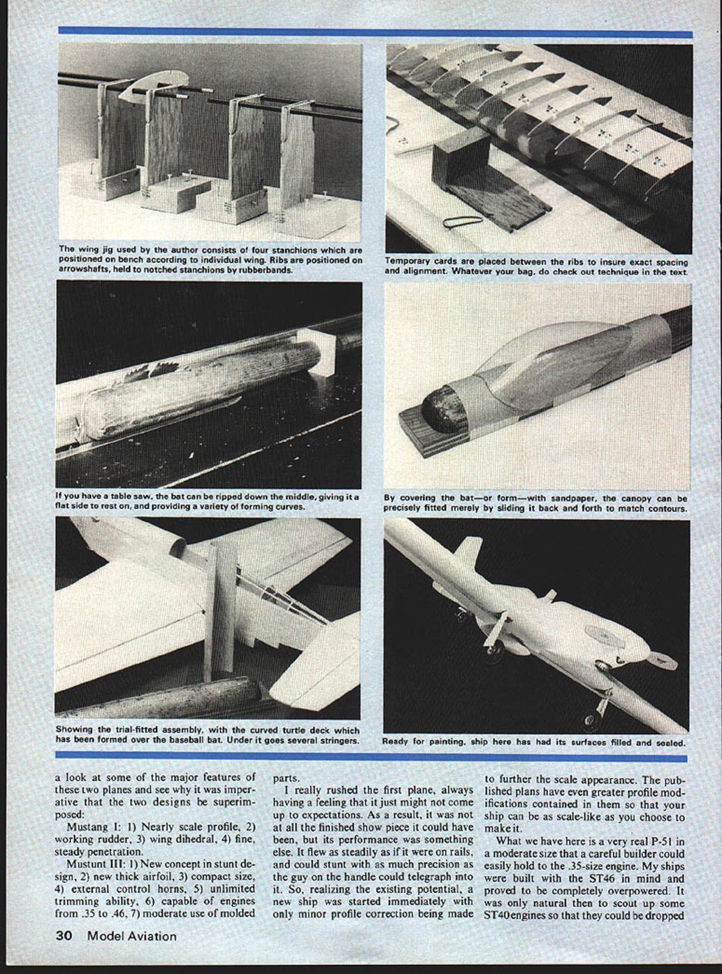
In setting up the jig, I usually locate the inner stanchions in the third or fourth bay from center. You must go out as far as you can, and yet retain adequate clearance from the trailing edge and the spar. The outer stanchions go outside of the wing, just beyond the tip rib. After the ribs are slipped to their approximate position, and the arrow shafts have been joined over the metal tubes, the entire assembly is dropped into the stanchion notches and rubber-banded down. The ribs are then spaced accurately; I prefer to use precisely-cut cards placed between all the ribs. These cards are left in place through the initial building steps.
Start by building the bottom first. Build it completely, including the landing gear, sheeting or cap strips. Remove the rubberbands. Reband the wing, flip the wing over, and again rubber-band it tightly, and finish the top construction. If you are fully sheeting the wing, you will not be able to retain the center stanchions when you go to the top side. They will have to be replaced by external support in the center, and here is where your boresighting ability is utilized to insure that you retain a well-aligned jig.
You will also appreciate the fact that, when it comes to installing the controls, you will be able to back the arrow shafts out of the center compartment, and then rejoin at least the rear shafts afterward. Remember the most important thing, however: your wing will only be as straight as the board or bench to which you fasten your jig stanchions.
Dihedral:
In order to control the roll balance of the low-winged Mustang, it is necessary that one inch of dihedral be built into the wing structure. How you do this is up to you, but I have been extremely successful using a variation of the step-up method, devised by Al Rabe, wherein each rib rises 1/16 in. on the way to the tip. A gauge for punching the ribs is drawn on the plan and, if used properly, will give excellent results.
First, secure a well oversized piece of acetate, say about 6 X 10, and lay it over the entire gauge drawing. At this point, we are only trying to locate the jig holes. Mark the locations on the acetate, and then, after removing it to a proper cutting surface, proceed to punch the jig holes, using a sharpened 5/16 brass tube, and one of the jig stanchions, as a spacing guide. Place the root rib precisely on the rib centerline, and tape it down temporarily. Return the acetate, locating the holes parallel to the centerline, but high on the rib, about 1/8 in. below the top edge at the rear hole. Tape the acetate down to keep it from moving, while you proceed to scribe the top line of the gauge, and the vertical line at the right into its surface. Remove the acetate, cut it precisely at the two lines just scribed, and you are ready to punch the jig holes in the remaining ribs. It is wise to number the ribs, and then do each in turn from root to tip, by placing it precisely on the trailing edge line, and being certain the line passes through dead center of the bird's mouth at the front of the rib. Lower the acetate sheet 1/16 in. at a time, making sure that it is against the vertical line at the right. I recommend that you glue a strip of cardboard on this line as a positive guide.
When you have punched all the ribs, and have slipped them on the jig, you will have a perfect rise to the tip, creating a dihedral of 3/4 in. By locating the leadouts 1/4 in. above the center of the wing tip, you will have achieved the full one-inch rise required. Let me repeat that any method of attaining this dihedral is alright and, although the method just described is rather involved, it is near perfect, and offers a super-critical method of monitoring the wing alignment by the simple process of bore-sighting through the arrow shafts.
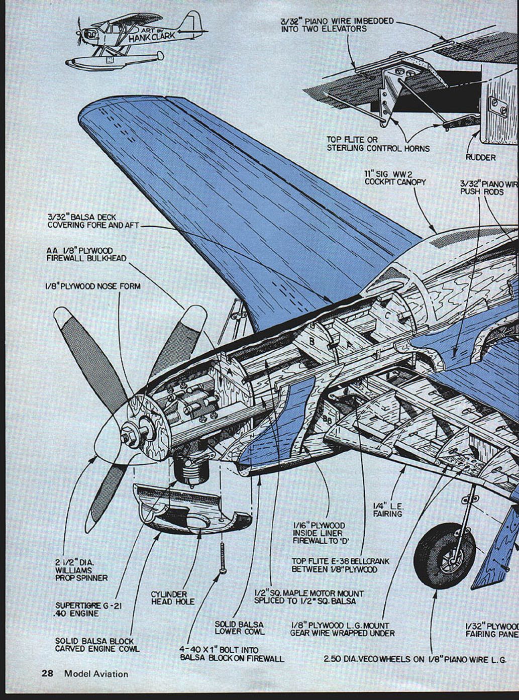
The Fuselage:
The fuselage is of simple box-type construction, and roomy enough for any activity. All I can add to the common method of construction is this: I drill my engine holes in the maple bearers before they are glued to the sides. After they are glued to the sides, the engine is bolted in tightly, with offset if desired, and becomes a perfect holding device while the tail is brought together, and the firewall, bulkheads, and cross braces, are installed. By using the following method you can make a perfect front on the nose, prior to gluing on the nose ring. With the engine still in place, drill a 1/4-in. hole in a 6 X 6 piece of 3/4-in. lumber. Relieve it around the hole, so that it can slip over the engine thrust washer by about 1/4 in. Tack-glue the top cowl block into place. Cement a medium sandpaper onto the face of the board and mount it on the engine like a prop. Now draw it down progressively as you slowly turn it sanding away the nose of the ship. This will even compensate for engine offset, and will give you a neat cowl ring fit.
One of the greatest time savers I discovered in building the Mustang was the use of a baseball bat for a mold. The bat used, 2 3/8 in. in diameter, was sawed down the middle and mounted on a 3/4-in. base, and both the foredeck and turtledeck were molded on it. Bottom and top sheeting for many models could be formed in this manner; it takes a lot of grief out of this phase of building the fuselage. I do not soak the balsa prior to molding, but simply brush on Bo-Peep ammonia until the wood is well saturated and pliable. When it is quite rubbery, I apply it to the bat, wrapping it with elastic bandage material. You don't need a lot of pressure. Try not to create wrinkles in the bandage. If you do, they will most likely leave marks in the balsa. With the turtle and foredeck formed on the bat, it is also quite natural that you should shape the canopy on it too. Simply tape sandpaper to the bat and final sand the canopy to a precise fit. This method also produces a great tapered gluing edge nicely roughed up.
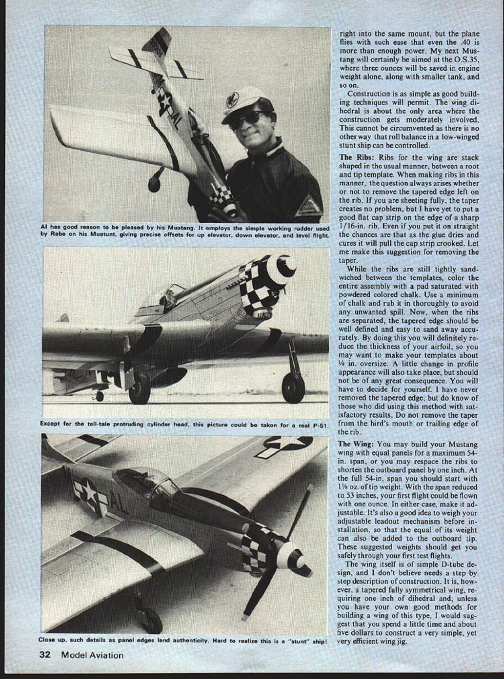
My Mustang has the simple working rudder of the Mustunt, all external and quite adjustable. Al has proposed the following as good starting positions on your working rudder. With up elevator, the rudder should be offset about 1/8 in. At neutral or level flight, about 1/4 in. At full down, the rudder should go to about 3/8 in. I have yet to hit these precise points on about ten working rudders I have made, but there is still a lot of comfort in knowing that, in the tough maneuvers, the little guy is out there really moving his tail for you. (Sorry, Al.) If you choose not to have a working rudder, at least have it adjustable, starting with about 3/8 in. offset.
A really great addition to your external nylon horns is the placement of a half-round peg under the horn platform. (See plan.) By alternately loosening or tightening the screws in the horn, you can achieve micrometer adjustments of 10° to 15° to either side of neutral. Using this system, quick-links could be eliminated almost entirely, even on RC jobs. There is nothing so safe and positive as a good Z bend.
There is little else I can add to this article than to recommend that you review the American Aircraft Modeler magazines for the following dates: June, 1969—Mustang, June 1970—Bearcat, February, 1973—Mustunt, and March, 1973—Sea Fury. I have always considered these articles to be among the most enlightening I have ever read. If you don't have these issues in your collection I would suggest that you make an effort to acquire them. Should you care to contact me during the construction of your Mustang I'll be more than happy to hear from you. (Al Meyers, 666 Orr St., Joliet IL 60436.)
Transcribed from original scans by AI. Minor OCR errors may remain.

