
Cover Story: Fairchild Ranger 24
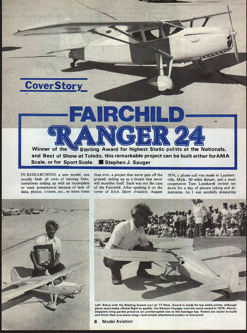
Winner of the Sterling Award for highest Static points at the Nationals, and Best of Show at Toledo, this remarkable project can be built either for AMA Scale, or for Sport Scale. Stephen J. Sauger
IN RESEARCHING a new model, one usually finds all sorts of missing links, sometimes ending up with an incomplete or weak presentation because of lack of data, photos, 3-views, etc., or, more often than not, a project that never gets off the ground, ending up as a dream that never will manifest itself. Such was not the case of the Fairchild. After spotting it on the cover of EAA Sport Aviation, August 1974, a phone call was made to Lambertville, Mich., 60 miles distant, and a most cooperative Tom Leonhardt invited me down for a day of picture taking and dimensions. As I was carefully measuring various components, Tom was tracing the elliptical shapes of the tips on newspaper with a marking pen. It is hard to beat that kind of cooperation. But it didn't end there. Imagine the feeling when Tom invited me for a ride in their yellow beauty.
The airplane evolved from the Fairchild 22, using the same wing as the parasol 22 model, and then adding flaps. Although the transition from the 22 to the 24 model included an American Cirrus engine, it was best remembered for the Warner Scarab. In 1935, when the flaps were added, a 145-hp Ranger engine was installed. During the war years, there was a military version known as Model VC-86 Forwarder, and production continued after the war by Temco Mfg. of both the 165-hp Warner 24W-46 and the 175-200-hp Ranger 24R-46.
The model is built to 1/6th scale and flying weight is 10½ lbs. At 800 sq. in. of wing area, this results in a 30-oz. wing loading. The heavier wing loading contributes to the model's stability in high winds, as was evidenced at the recent Tournament of Champions event in Las Vegas, and the high-lift Clark Y airfoil enables low speed control, with the model normally flown at half throttle.
There are two schools of thought concerning construction, especially important in scale models. Build 'em strong in order to survive impacts on one hand, on the other, and keep 'em light, because once they hit it's all over anyway. I think we can take credence in both approaches, depending on the particular type of project. I prefer the former, because my first flight at Las Vegas was a disaster, flying along at 10-feet altitude. An airplane that never should have taken off; an engine barely at half throttle; this stubborn author insisted on attempting to fly against the wishes of an able John Roth, and managed to baby the Fairchild into the air and straight ahead for about 300 yards at no higher than 8-10 feet, daring not to turn one way or the other, at which point the model fell out of the sky. Damage was minimal, just nose cowl and landing gear fairing.
The plane was back into the air within the hour and completed two successful flights. I highly doubt this feasible with a lighter built construction, and I see no practicality in sacrificing strength. A properly designed model can inherit tremendous strength by simple techniques, and no penalty in weight. The model is designed along conventional lines, and frequent references to the perspective sketches should help clarify all of the problem areas.
Fuselage:
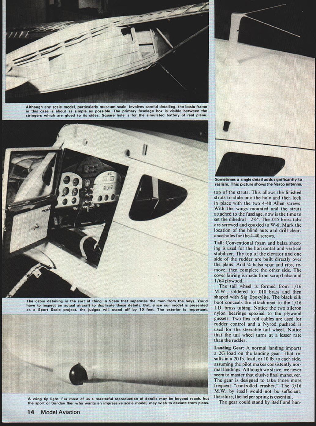
Begin by familiarizing yourself with the various shapes and types of wood, especially in the firewall and cabin areas. Preassemble the 1/32 plywood cabin sides with epoxy to the 3/32-balsa fuselage sides. Cement 1/4 sq. longerons and 1/4 x 3/16 vertical balsa supports, and the box construction is ready for assembly. Two items of mention, before assembling the 1/16 plywood cabin top, screw and epoxy two maple blocks with pre-drilled clearance holes for the sliding brass tubing. Secondly, attach with screws, and epoxy the two .015 brass plates to the 1/16 plywood bottom before assembling sides.
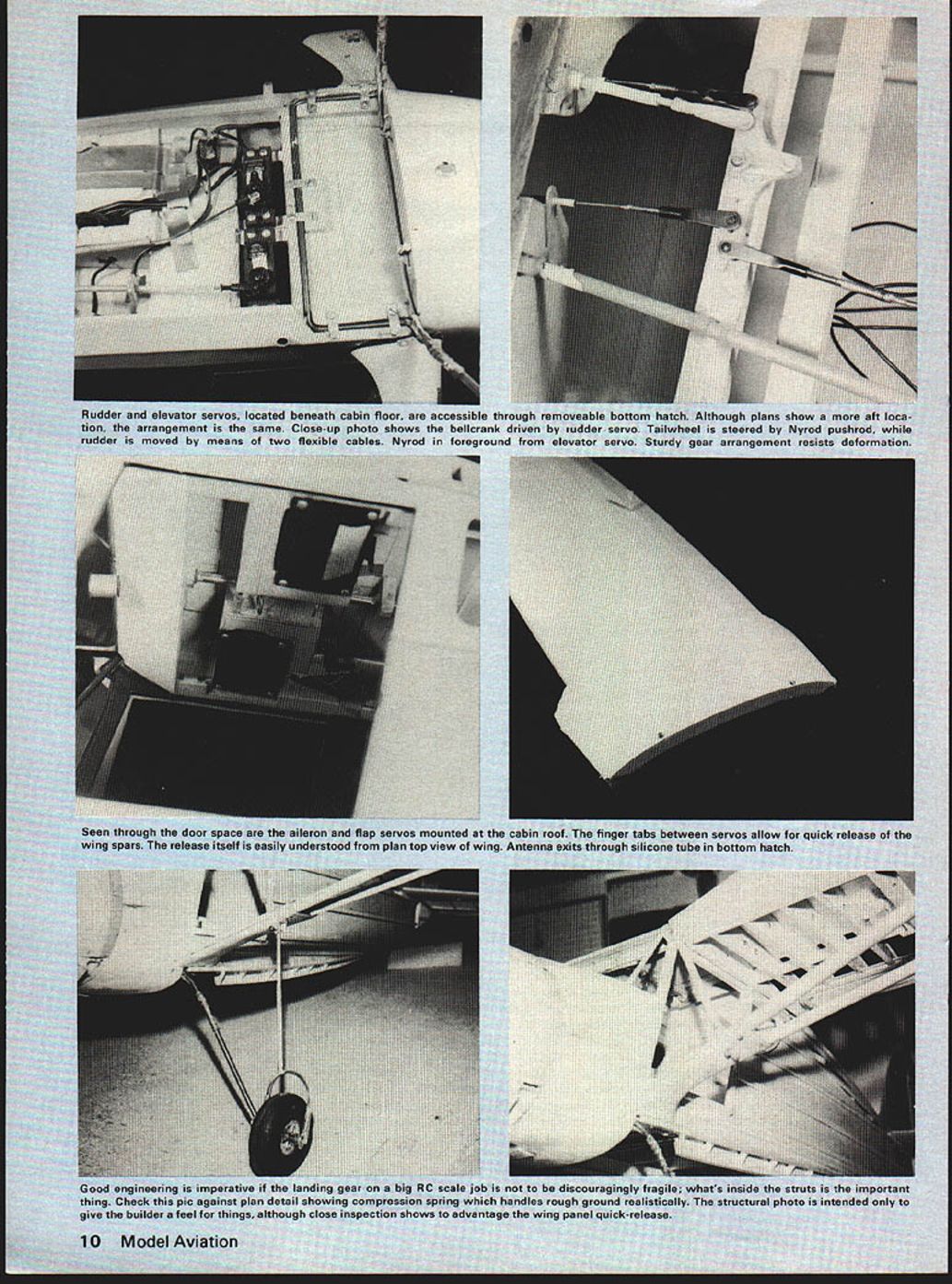
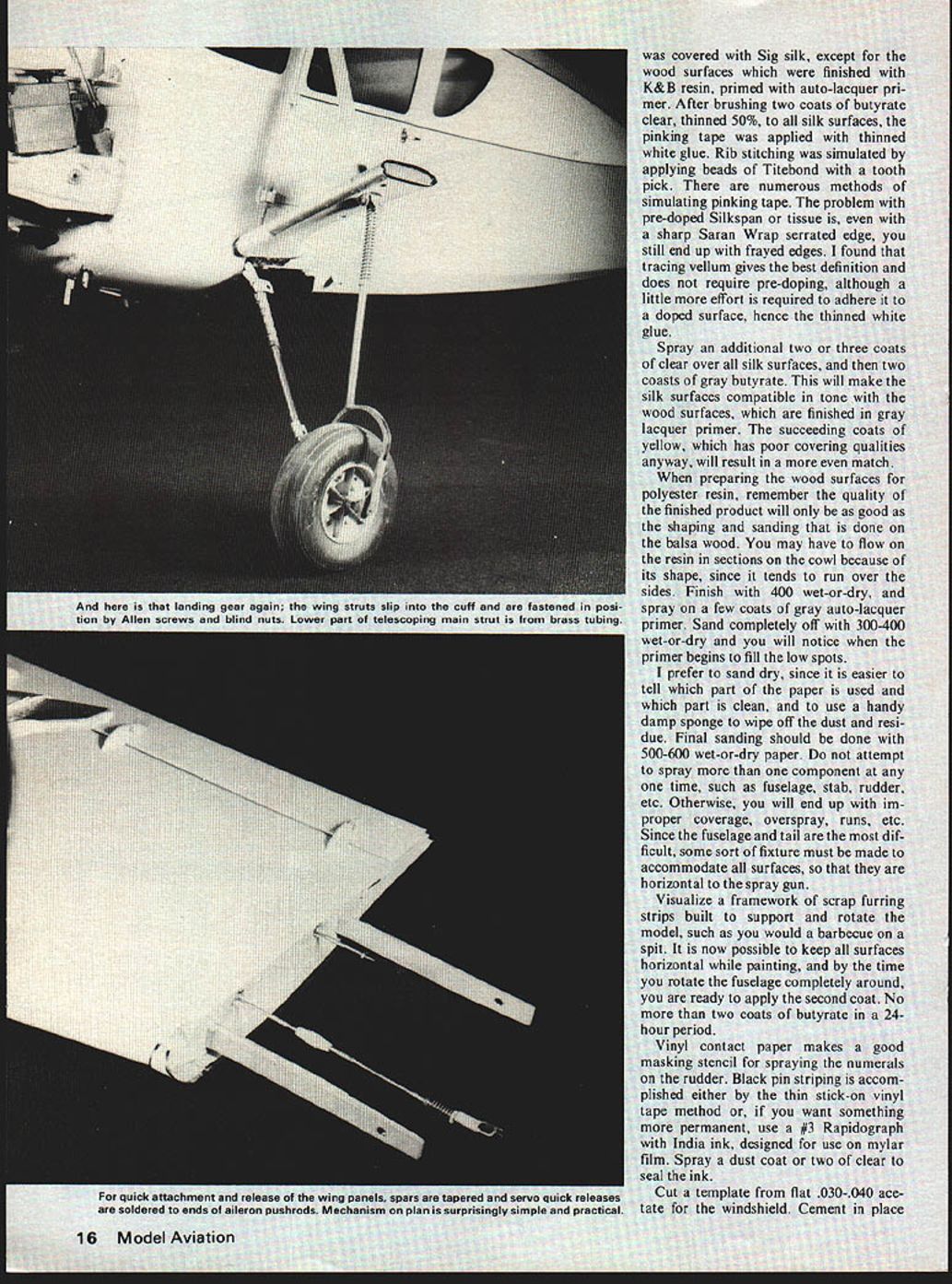
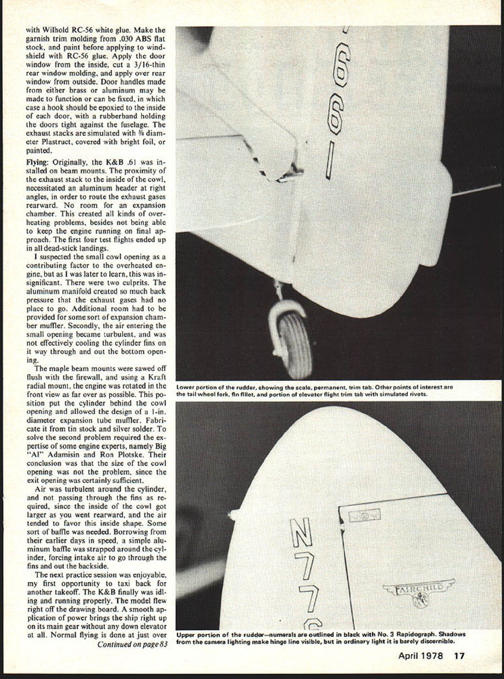
After framing the door opening, and before stringers, the landing gear main fairing and 3/16 dowel compression strut can Good engineering is imperative if the landing gear on a big RC scale job is not to be discouragingly fragile; what's inside the struts is the important thing. Check this pic against plan detail showing the compression spring which handles rough ground realistically. The structural photo is intended only to give the builder a feel for things, although close inspection shows to advantage the wing panel quick-release. be attached firmly to the fuselage. The front end firewall superstructure can be preassembled and then joined to the cabin box construction. After installing door hinges and maple blocks for the landing gear straps, complete the front with scrap balsa blocks and 1/4" sheeting. You are now ready for formers and stringers.
The top stringers will have to be tapered to flush up with the 3/8" spruce cross-brace across top of windshield. The nose cowl is built separately. It is made from four laminated balsa rings cemented over two keels and then planked. After fiberglassing, the keels are removed and the cowl top is separated. The bottom hatch is very basic, using a dowel pin aft and two anchor screws up front. This provides access to the radio gear and landing gear.
Wings:
Separate wing panels are no more difficult to build than one wing panel. It requires a few more minutes of set up time at the flying field, but you have an undisturbed surface across the top of the fuselage. Two panels are easier to cover and paint, and it takes up less room in a trunk or box.
After all the ribs are cut out, slide two spruce spars through the holes and position over plan. Place a 3/32" shim under rear edge of W-7. This creates proper amount of wash-out. The spars must be reinforced with 1/16" plywood and tapered as shown, then drill a clearance hole for the sliding brass tubing. The design of the wing attaching mechanism incorporates two 5/32" I.D. brass tubes sliding fore and aft over a 5/32" O.D. brass tube. The inner tube is stationary. By squeezing the two finger tabs, the tubes are disengaged from the wing spars. The fixed plate soldered to the inner tube and epoxied to the cabin top assures equal disengagement.
In addition, the aileron and flap pushrod employ a quick disconnect. A brass retainer is formed to slide along the music wire, and the spring tension locks it in place through the DuBro clevis and servo arm. Cement the plywood reinforcements cross grain to the spruce struts, and install four 4-40 blind nuts.
Now attach the struts to the main gear fairing. Complete shaping the fairing with scrap balsa and use 1/64" plywood over the
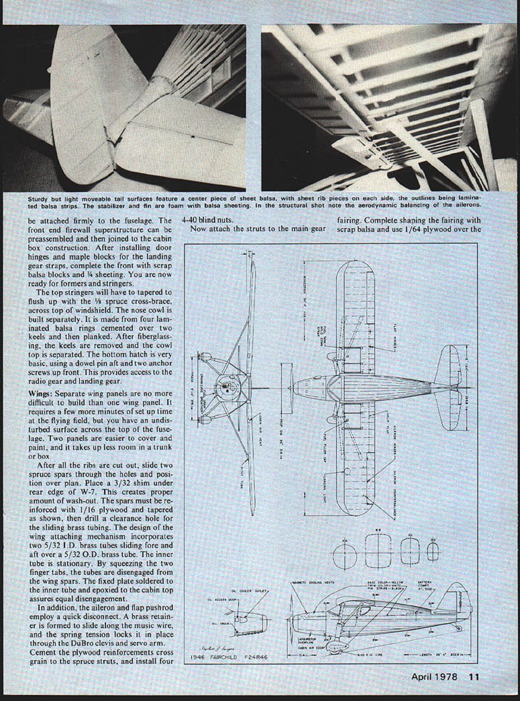
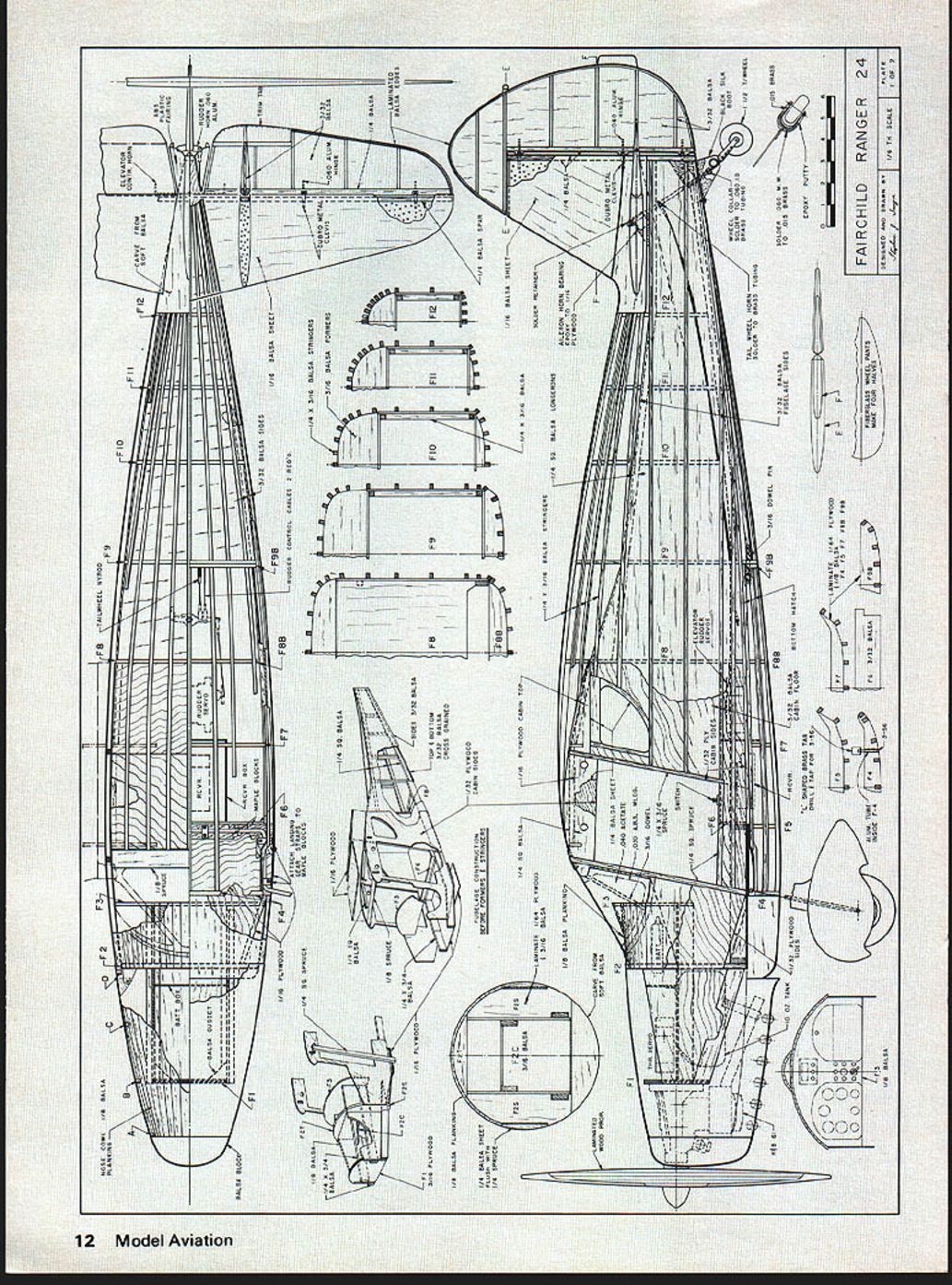
FAIRCHILD RANGER 24
No continuous article text appears on this scanned page — it is the full-size plan sheet with component labels and drawings only.
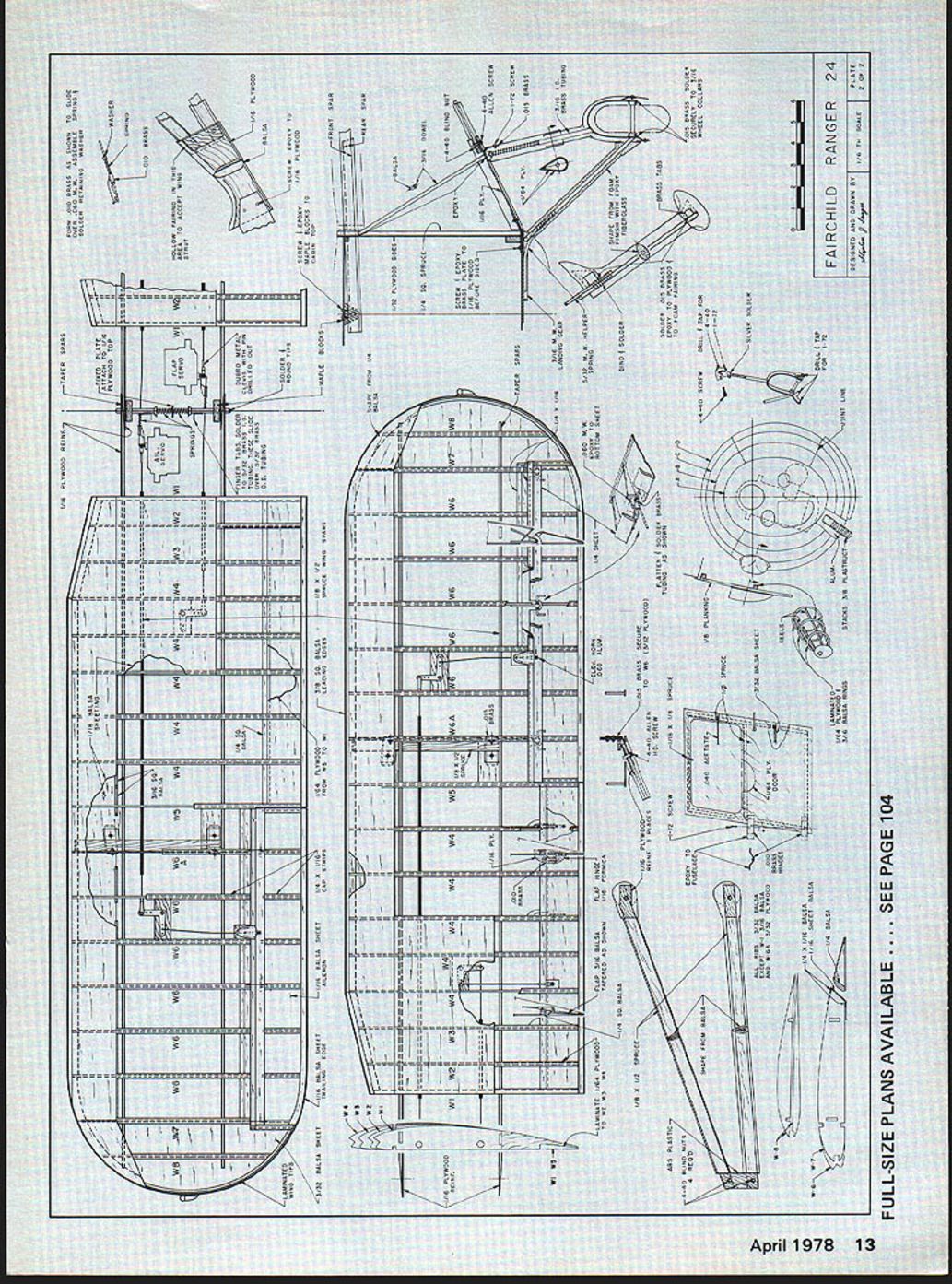
FAIRCHILD RANGER 24
top of the struts. This allows the finished struts to slide into the hole and then lock in place with the two 4-40 Allen screws. With the wings mounted and the struts attached to the fuselage, now is the time to set the dihedral—2½°. The .015 brass tabs are screwed and epoxied to W-6. Mark the location of the blind nuts and drill clearance holes for the 4-40 screws.
Tail:
Conventional foam and balsa sheeting is used for the horizontal and vertical stabilizer. The top of the elevator and one side of the rudder are built directly over the plans. Add 1/4" balsa spar and ribs, remove, then complete the other side. The cover fairing is made from scrap balsa and 1/64" plywood.
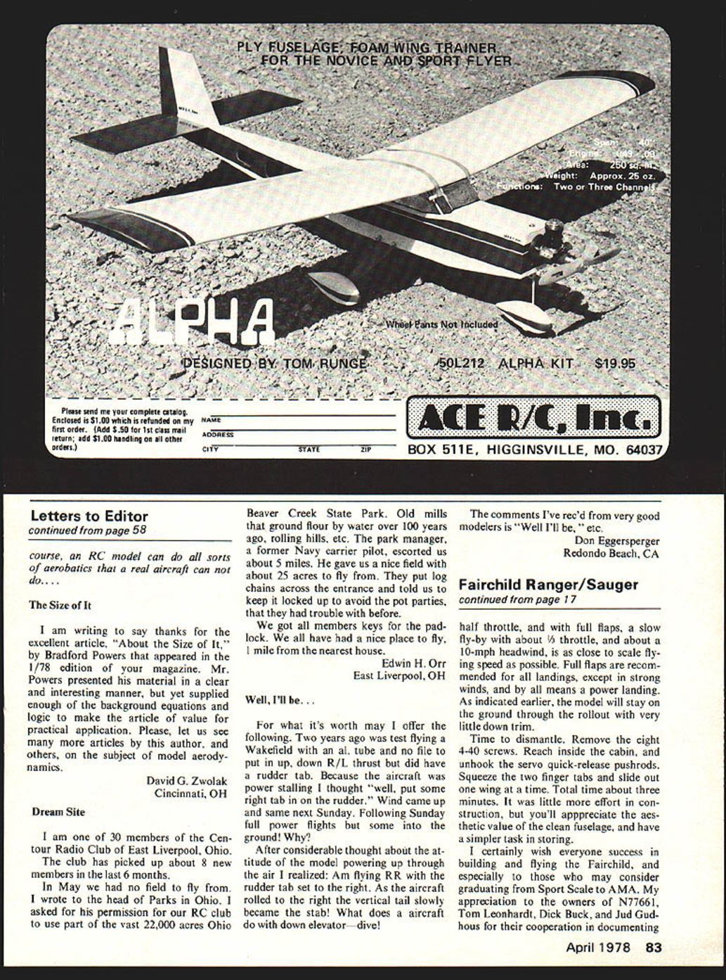
The tail wheel is formed from 1/16" M.W., soldered to .010" brass and then shaped with Sig Epoxylite. The black silk boot conceals the attachment to the 1/16" I.D. brass tubing. Notice the two aileron nylon bearings epoxied to the plywood gussets. Two flex rod cables are used for rudder control and a Nyrod pushrod is used for the steerable tail wheel. Notice that the tail wheel turns at a lesser rate than the rudder.
Landing Gear:
A normal landing imparts a 2G load on the landing gear. That results in a 20 lb. load, or 10 lb. to each side, assuming the pilot makes consistently normal landings. Although we strive, we never seem to master that elusive final maneuver. The gear is designed to take those more frequent "controlled crashes." The 3/16" M.W. by itself would not be sufficient, therefore, the helper spring is essential.
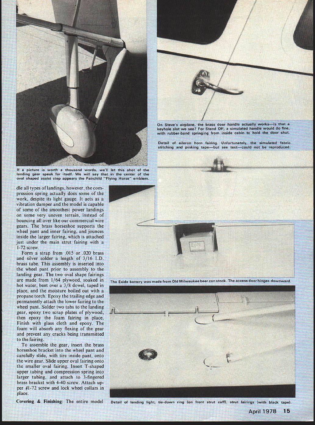
The gear could stand by itself and handle a 30 lb. load without distorting the fuselage. The helper spring is made from 3/32" music wire and is secured to the fuselage with a screw and washer. It will handle all types of landings; however, the compression spring actually does some of the work, despite its light gauge. It acts as a vibration damper and the model is capable of some of the smoothest power landings on some very uneven terrain, instead of bouncing all over like our commercial wire gears. The brass horseshoe supports the wheel pant and inner fairing, and jounces inside the larger fairing, which is attached just under the main strut fairing with a 1-72 screw.
Form a strap from .015 or .020 brass and silver solder a length of 3/16 I.D. brass tube. This assembly is inserted into the wheel pant prior to assembly to the landing gear. The two oval shape fairings are made from 1/64" plywood, soaked in hot water, bent over a 3/8" dowel, taped in place, and the moisture boiled out with a propane torch. Epoxy the trailing edge and permanently attach the lower fairing to the wheel pant. Solder two tabs to the landing gear, epoxy two scrap plates of plywood, then epoxy the foam fairing in place. Finish with glass cloth and epoxy. The foam will absorb any flexing of the gear and prevent any cracks being transmitted to the fairing.
To assemble the gear, insert the brass horseshoe bracket into the wheel pant and carefully slide, with tire inside pant, onto the wire gear. Slide upper oval fairing onto the smaller oval fairing. Insert T-shaped upper tubing and compression spring into larger tubing, and attach to 3-fingered brass bracket with 4-40 screw. Attach upper 1-72 screw and lock wheel collars in place.
Covering & Finishing:
The entire model was covered with Sig silk, except for the wood surfaces which were finished with K&B resin, primed with auto-lacquer primer. After brushing two coats of butyrate clear, thinned 50%, to all silk surfaces, the pinking tape was applied with thinned white glue. Rib stitching was simulated by applying beads of Titebond with a tooth pick. There are numerous methods of simulating pinking tape. The problem with pre-doped Silkspan or tissue is, even with a sharp Saran Wrap serrated edge, you still end up with frayed edges. I found that tracing vellum gives the best definition and does not require pre-doping, although a little more effort is required to adhere it to a doped surface, hence the thinned white glue.
Spray an additional two or three coats of clear over all silk surfaces, and then two coats of gray butyrate. This will make the silk surfaces compatible in tone with the wood surfaces, which are finished in gray lacquer primer. The succeeding coats of yellow, which has poor covering qualities anyway, will result in a more even match.
When preparing the wood surfaces for polyester resin, remember the quality of the finished product will only be as good as the shaping and sanding that is done on the balsa wood. You may have to flow on the resin in sections on the cowl because of its shape, since it tends to run over the sides. Finish with 400 wet-or-dry, and spray on a few coats of gray auto-lacquer primer. Sand completely off with 300-400 wet-or-dry and you will notice when the primer begins to fill the low spots.
I prefer to sand dry, since it is easier to tell which part of the paper is used and which part is clean, and to use a handy damp sponge to wipe off the dust and residue. Final sanding should be done with 500-600 wet-or-dry paper. Do not attempt to spray more than one component at any one time, such as fuselage, stab, rudder, etc. Otherwise, you will end up with improper coverage, overspray, runs, etc. Since the fuselage and tail are the most difficult, some sort of fixture must be made to accommodate all surfaces, so that they are horizontal to the spray gun.
Visualize a framework of scrap furring strips built to support and rotate the model, such as you would a barbecue on a spit. It is now possible to keep all surfaces horizontal while painting, and by the time you rotate the fuselage completely around, you are ready to apply the second coat. No more than two coats of butyrate in a 24-hour period.
Vinyl contact paper makes a good masking stencil for spraying the numerals on the rudder. Black pin striping is accomplished either by the thin stick-on vinyl tape method or, if you want something more permanent, use a #3 Rapidograph with India ink, designed for use on mylar film. Spray a dust coat or two of clear to seal the ink.
Cut a template from flat .030-.040 acetate for the windshield. Cement in place with Wilhold RC-56 white glue. Make the garnish trim molding from .030 ABS flat stock, and paint before applying to windshield with RC-56 glue. Apply the door window from the inside, cut a 3/16-in. thin rear window molding, and apply over rear window from outside. Door handles made from either brass or aluminum may be made to function or can be fixed, in which case a hook should be epoxied to the inside of each door, with a rubber band holding the doors tight against the fuselage. The exhaust stacks are simulated with 3/8" diameter Plastruct, covered with bright foil, or painted.
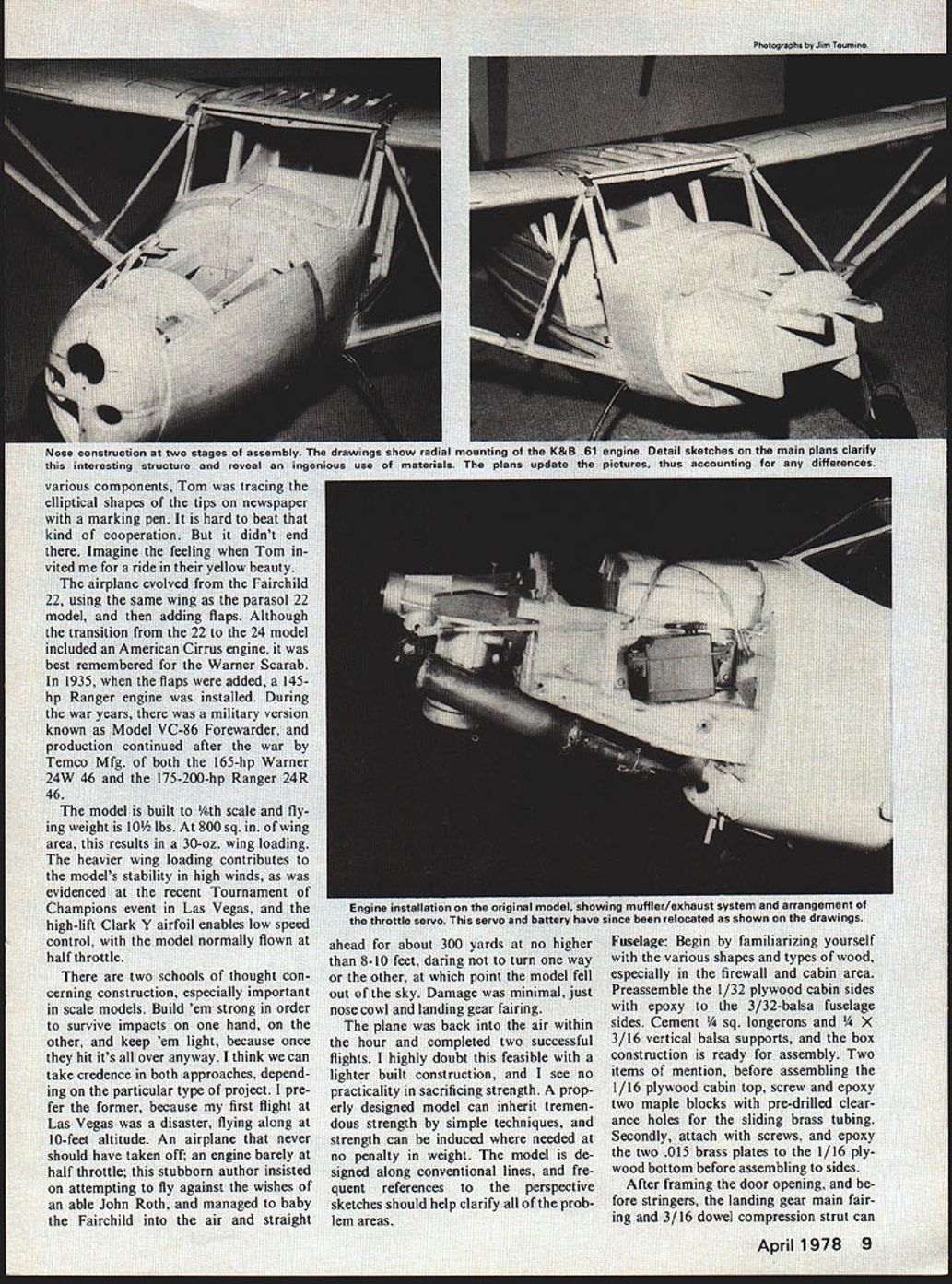
Flying: Originally, the K&B .61 was installed on beam mounts. The proximity of the exhaust stack to the inside of the cowl necessitated an aluminum header at right angles, in order to route the exhaust gases rearward. No room for an expansion chamber. This created all kinds of overheating problems, besides not being able to keep the engine running on final approach. The first four test flights ended up in all dead-stick landings.
I suspected the small cowl opening as a contributing factor to the overheated engine, but as I was later to learn, this was insignificant. There were two culprits. The aluminum manifold created so much back pressure that the exhaust gases had no place to go. Additional room had to be provided for some sort of expansion chamber muffler. Secondly, the air entering the small opening became turbulent, and was not effectively cooling the cylinder fins on its way through and out the bottom opening.
The maple beam mounts were sawed off flush with the firewall, and using a Kraft radial mount, the engine was rotated in the front view as far over as possible. This position put the cylinder behind the cowl opening and allowed the design of a 1-in. diameter expansion tube muffler. Fabricate it from tin stock and silver solder. To solve the second problem required the expertise of some engine experts, namely Big "Al" Adamisin and Ron Plotske. Their conclusion was that the size of the cowl opening was not the problem, since the exit opening was certainly sufficient.
Air was turbulent around the cylinder, and not passing through the fins as required, since the inside of the cowl got larger as you went rearward, and the air tended to favor this inside shape. Some sort of baffle was needed. Borrowing from their earlier days in speed, a simple aluminum baffle was strapped around the cylinder, forcing intake air to go through the fins and out the backside.
The next practice session was enjoyable, my first opportunity to taxi back for another takeoff. The K&B finally was idling and running properly. The model flew right off the drawing board. A smooth application of power brings the ship right up on its main gear without any down elevator at all. Normal flying is done at just over
Fairchild Ranger/Sauger
half throttle, and with full flaps, a slow fly-by with about 1/3 throttle, and about a 10-mph headwind, is as close to scale flying speed as possible. Full flaps are recommended for all landings, except in strong winds, and by all means a power landing. As indicated earlier, the model will stay on the ground through the rollout with very little down trim.
Time to dismantle. Remove the eight 4-40 screws. Reach inside the cabin, and unhook the servo quick-release pushrods. Squeeze the two finger tabs and slide out one wing at a time. Total time about three minutes. It was little more effort in construction, but you'll appreciate the aesthetic value of the clean fuselage, and have a simpler task in storing.
I certainly wish everyone success in building and flying the Fairchild, and especially to those who may consider graduating from Sport Scale to AMA. My appreciation to the owners of N77661, Tom Leonhardt, Dick Buck, and Jud Gudhouse for their cooperation in documenting the model, and their continued interest in the model itself, more so than their full-scale prototype. And it looks like some of it has worn off already. Word has it that Dick Buck is now flying one of Bob Hisey's ships at the Toledo Weak Signals field. Welcome to scale.
Transcribed from original scans by AI. Minor OCR errors may remain.

