
Cox Special
Biplanes have always held a special attraction for me as a modeler. There's something about an airplane with two wings that fastens your attention. Biplanes came along during the period when barnstormers and air shows flourished. Aviation was still glamorous and exciting in those days, and biplanes contributed much to its development. Though I've built quite a few two‑wingers over the years, I never tire of their classical appearance.
Since I'm a longtime pilot and aviation enthusiast, I wanted the Cox Special to resemble a full‑size airplane as closely as possible. This meant using a built‑up fuselage and wings, and making the engine as fully enclosed as possible. Even so, the model is relatively easy to build. Keeping the airplane small and using a 1/2A‑size engine also helps drive down the cost of building and flying it.
The model's resemblance to the Pitts Special and the EAA Biplane shouldn't be surprising. Most of the inspiration came from these two airplanes. The model's name is a spin‑off from the Pitts Special, still considered one of the finest aerobatic airplanes in the world. A friend, Mr. C. B. Messer, owns and flies a Pitts, and the two of us have logged a few hours in the EAA Biplane as well.
Construction
If you're new to building from plans, look them over carefully and review the text before you begin construction. Since this model follows basic construction procedures, everything should be fairly straightforward if you've built a few models from plans already.
I used standard off‑the‑shelf balsa—around 6‑ to 8‑lb. stock. Be a little more selective if you're looking for maximum performance. Since it's a small model, 4‑ to 6‑lb. stock can be used for most parts. The main thing to remember is to stay away from wood that's brittle and hard, or the kind that's soft and mushy.
Except where epoxy is called for, aliphatic resin (yellow carpenter's glue) is the adhesive used throughout the model. The yellow aliphatic glues sand much better than white glues. Try not to overdo the epoxy where used; this glue is as heavy as it is strong.
Tight‑fitting joints and a thin coat of glue on mating surfaces produce a strong, lightweight model. Large blobs of glue add excessive weight and detract from the final appearance.
Make sure your building board is warp free and firm enough to hold pins securely. Your local building supply store should have suitable material.
Tail surfaces
Since these parts take less time to build, I usually make them first. Cut the stabilizer, elevator, fin, and rudder from 3/32‑in. sheet balsa. If you decide to use nylon hinges, carefully cut out the hinge slots. I used small Du‑Bro hinges on the prototype. The outboard hinges that fit in the elevator will need to be trimmed a little short.
Cloth hinges can be used instead; they're somewhat easier to install but don't look as nice. If you use them, be sure to install the elevator horn beforehand. The elevators are joined together with a 1/8‑in. dowel.
Wings
Don't be turned off by the idea of building two wings. Two don't take much more time to build than one, and they're twice as much fun. Both wings are built in one piece with no dihedral.
Building the bottom wing:
- Begin by shaping the 1/8 x 1/2‑in. trailing edge stock with a sanding block. Alternatively, you may use formed trailing edge material.
- Pin down the leading edge, spar, and trailing edge, and glue the ribs in place. When gluing the double‑strut ribs, insert a scrap of 1/8‑in. balsa between them to act as a temporary spacer. The three center ribs are undercut 1/16 in. on top to allow for the center‑section sheeting.
- Glue the 3/32‑in. balsa wing tips in place, being sure to raise them 3/16 in. as shown on the plans. Glue 1/4‑in. triangular stock in place against the tip ribs and the leading edge.
- Once the glue is dry, remove the wing from the building board. Add 1/16‑in. balsa center‑section sheeting to the top only. Glue a 1/16‑in. balsa strip between the double‑strut ribs, making sure it's flush with the bottom.
- Sand the leading edge and wing tips to shape. Glue 4 oz. of lead in place on the right bottom wing before covering.
Building the top wing:
- Pin down the leading edge, spar, and trailing edge as you did with the bottom wing. Glue the 1/4 x 5/16‑in. balsa center section to the trailing edge.
- Add the ribs and wing tips, trimming the three center ribs at the rear for proper fit. Add the 1/8‑in. balsa piece into which the center‑section struts will be fitted.
- The wing strut is a 3/16‑in. dowel which is glued into a slot in the wing strut fairings. Wing strut fairings are 1/16‑in. plywood.
- A 1/16‑in. plywood lead‑out guide is epoxied on the left wing strut. The completed wing struts will be glued in place after the wing has been covered.
The lines of both the Pitts Special and the EAA Biplane can be seen in this semiscale 1/2A control‑line (CL) biplane. Construction is straightforward yet the model is an eye‑catcher at the flying circle.
Fuselage
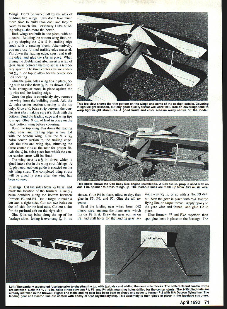
Cut the fuselage sides from 1/8‑in. balsa and mark the location of the formers. Glue 1/16‑in. balsa doublers along the bottom between formers F2 and F5. Make a left and a right side. Cut two holes on the left side for the lead‑outs and a slot for the pushrod exit on the right side.
Glue 1/4‑in. square balsa along the top of the fuselage sides, letting it overhang 1/16 in. as shown on the plans. Glue former F4 in place, allow to dry, then glue in F5, F6, and F7. Glue the tail together.
Bend the landing‑gear wires from .062 music wire, making the main gear which fits on F2 first. Draw the gear outline on F2 and drill holes for the landing‑gear lacing about every 3/16 in. with a No. 59 drill. Sew the gear in place with 1/2A Dacron flying line or carpet thread. Apply epoxy to the gear wire and thread, and glue F2 in place.
Glue formers F3 and F3A together, then spot‑glue them in place on the fuselage. To bend the rear gear wire, first make a pattern using a soft wire such as florist's wire. After checking fit, bend the rear gear out of .062 music wire, mark the gear outline on F3, break the former from the fuselage, join the gear to F3, and glue it in place. When dry, bind the gear legs together with soft copper wire and solder the legs together.
Drill a 3/32‑in. hole in the plywood bellcrank plate. Slide the plate in place and glue it securely. Bend the pushrod and lead‑out lines from music wire. Add the lead‑out lines to the bellcrank, then mount the assembly in the fuselage. Add the pushrod, securing it to the bellcrank with copper wire and a drop of solder. Temporarily place the stabilizer and elevator, hook up the pushrod, and check the control system for smooth operation.
Drill mounting holes in the firewall for the 2‑25 blind nuts. After installing the blind nuts, put a little epoxy on their backs for added security. Glue the firewall in place, then add the 1/8‑in.‑sq. balsa top stringers. Bend the tail gear from .025 music wire and epoxy it to a piece of 1/32‑in. plywood; glue this to the inside of the fuselage, flush with the sides.
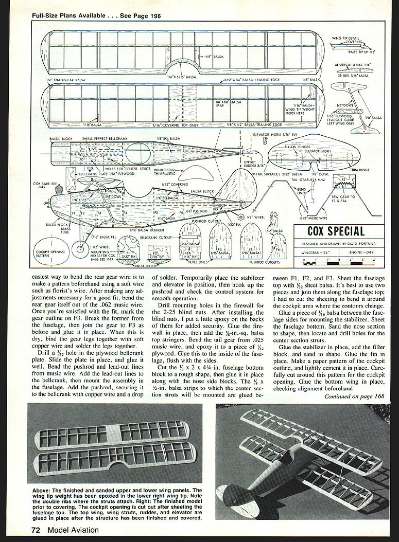
Cut the 1/8 x 2 x 4‑1/4‑in. fuselage bottom block to a rough shape, then glue it in place along with the nose side blocks. Glue the 1/8‑in. balsa strips to which the center‑section struts will be mounted between F1, F2, and F3. Sheet the fuselage top with 1/32‑in. sheet balsa—it's best to use two pieces joined along the fuselage top; cut the sheeting to bend it around the cockpit area where contours change.
Glue a piece of 1/16‑in. balsa between the fuselage sides for mounting the stabilizer. Sheet the fuselage bottom and sand the nose section to shape, then locate and drill holes for the center‑section struts. Glue the stabilizer in place, add the filler block, and sand to shape. Glue the fin in place.
Make a paper pattern for the cockpit outline and lightly cement it in place. Carefully cut around this pattern for the cockpit opening. Glue the bottom wing in place, checking alignment beforehand.
Fill any cracks or imperfections with balsa filler, and smooth all fuselage parts with 320‑grit sandpaper. Be careful around the turtledeck, since the balsa is only 1/16‑in. thick in that area. Epoxy 1/16‑in. balsa between the landing‑gear legs and add a drain tube under the fuselage bottom. Fuel‑proof the firewall and inside the cowling with a coat of epoxy glue or fiberglass resin, being careful to keep it off the blind nuts.
Covering and final assembly
I used lightweight silkspan to cover the wings. Sig Manufacturing Company carries a lightweight Japanese tissue called Lite‑Flite polyspan that will also work well. Lite‑Flite comes in a variety of colors and can be applied the same as silkspan. I don't recommend using iron‑on covering, since it can warp a lightweight structure if it's shrunk too much.
Before applying the silkspan, brush two coats of clear dope on all areas to be covered. Lightly sand the dope with 400‑grit paper where necessary. Apply the silkspan so the grain runs spanwise on the wings. I always wet the silkspan before applying it. Once the wrinkles are worked out, brush clear dope through the silkspan along the leading edge, trailing edge, and tips. Cut the wing strut openings after the wing has been completely covered. I covered the fuselage and tail surfaces to give the model a better finish, but this is optional.
For the final finish, brush three coats of clear dope on the model, followed by three coats of dope mixed with talcum powder. After sanding this down well, spray one or two coats of Model Master enamel to resemble an aerobatic biplane, which typically sports a flashy paint scheme. A final coat of clear dope will protect the finish and add gloss. For a lightweight model, three coats of dope would be acceptable.
If you're using nylon hinges on the elevator, epoxy them in place before installing the elevator—be careful not to get epoxy on the hinge pins. Install the elevator, and glue the rudder in place, offsetting it about 1/8 in. to the right.
An open‑cockpit model needs a pilot to look authentic. I used a Williams Bros. 1‑1/2‑in. scale pilot, although I had to trim his shoulders slightly to make him fit. Before gluing in the top wing, check alignment by mounting it to the outboard wing struts and dry‑fitting it in place. Once satisfied with alignment, glue the struts in place and allow thorough drying.
The center‑section struts are 1/8‑in. dowels cut so they protrude about 1/8 in. into the fuselage and wing. Paint the dowels before gluing them in place. Cut the windshield from thin plastic and epoxy it in place. The model uses commercial 1‑1/4‑in. rubber wheels, but 1‑1/16‑in. plastic wheels (available from Sig) are considerably lighter. Finally, install the engine and check the center of gravity.
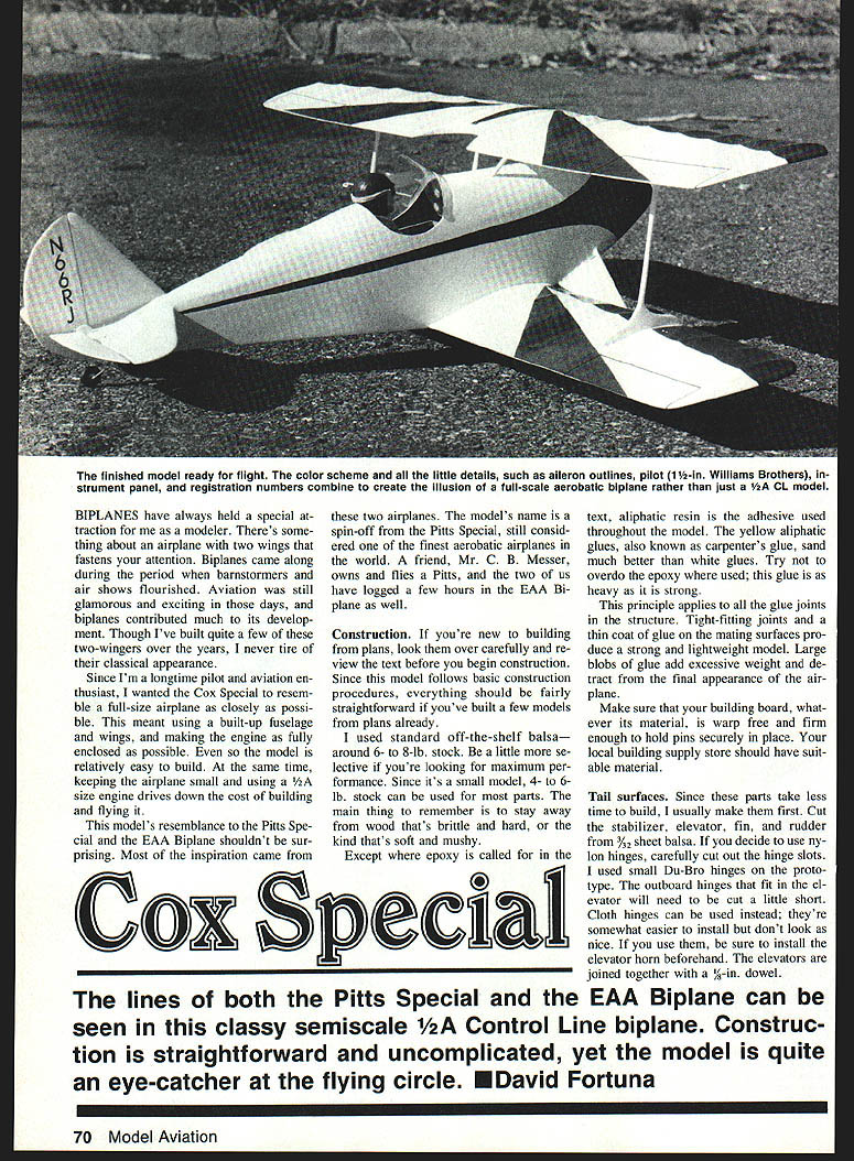
The finished model, ready to fly, with a flashy color scheme and details such as aileron outlines, pilot, 1‑1/2‑in. Williams Brothers instrument panel, and registration numbers, creates the illusion of a full‑scale aerobatic biplane rather than just a 1/2A CL model.
Flying
Do a preflight check to make sure the controls operate smoothly. I used a Cox gray 5 x 4‑in. propeller with an Ace 1‑in. spinner. Wait until there is no wind to make your first flights, and use 30‑ft lines. Because of their greater wing area and higher drag, biplanes customarily can't handle as much wind as other airplanes. In compensation, there's certainly nothing prettier in the air.
If you don't live near a well‑stocked hobby shop, everything you'll need to build and fly the Cox Special can be purchased directly from Sig Manufacturing Company at 401 South Front Street, Montezuma, IA 50171. Refer to the company's catalog (costs $3) for current prices and stock numbers.
Many happy landings!
— David Fortuna
Transcribed from original scans by AI. Minor OCR errors may remain.

