
Cricket
Paul F. Denson
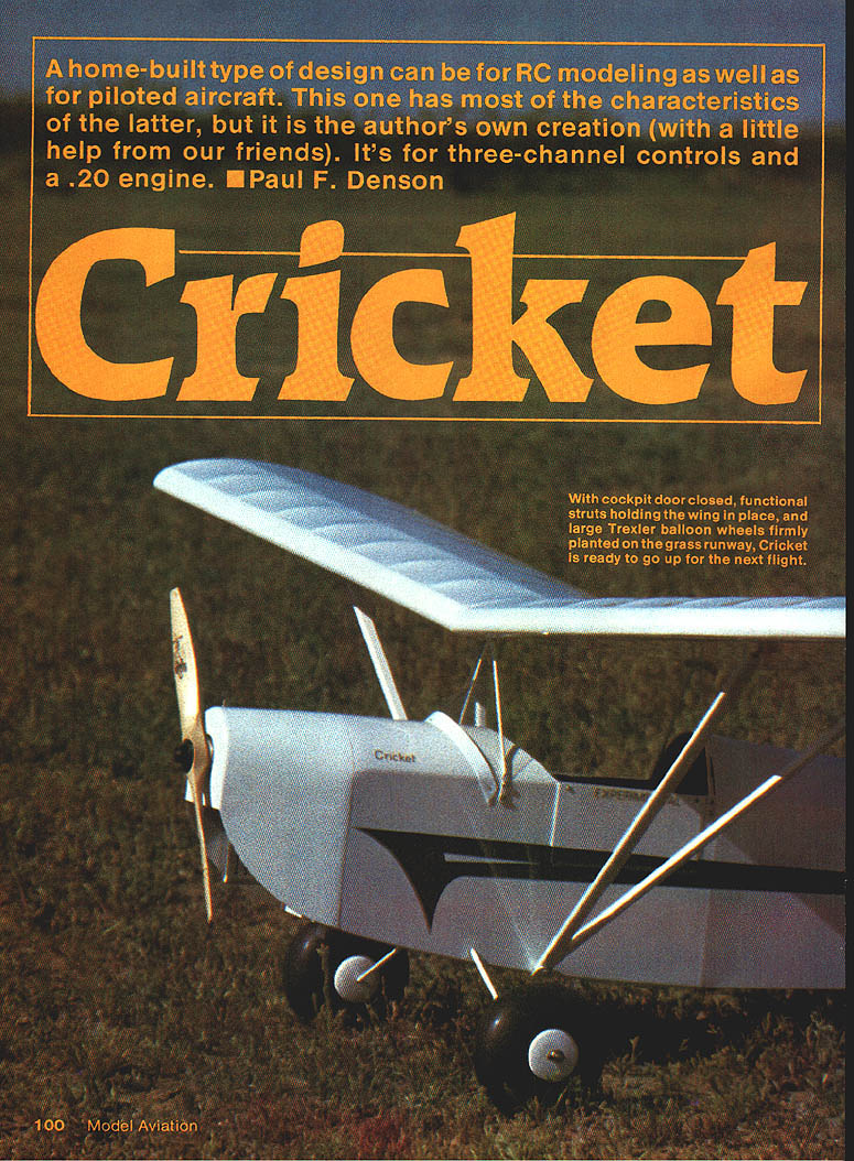
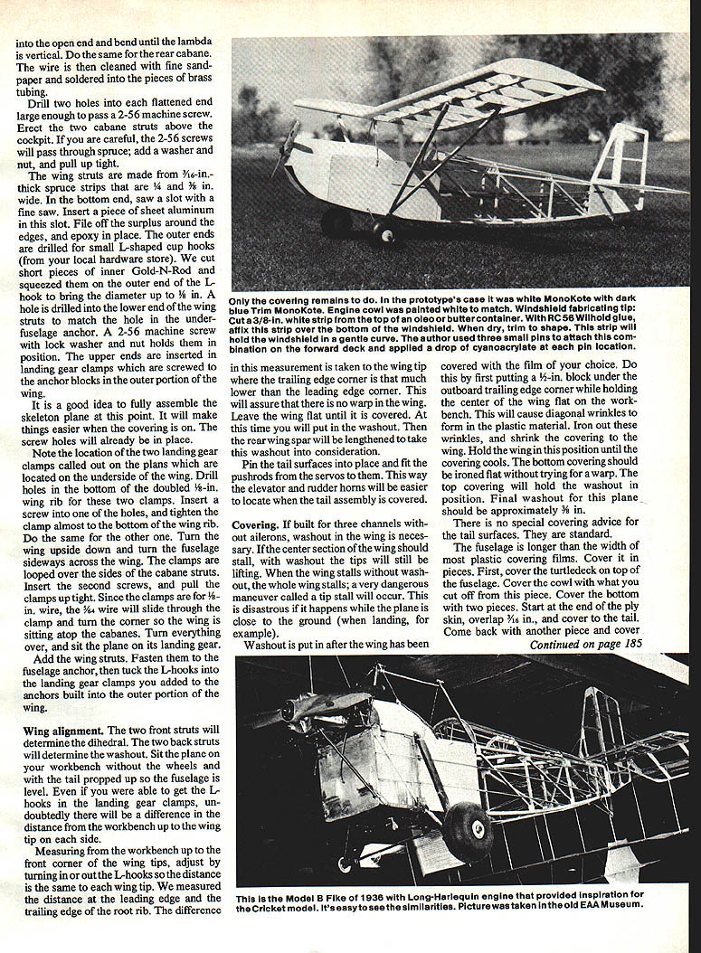
A home‑built design suitable for RC modeling as well as for piloted aircraft, the Cricket was developed as the author's own creation (with a little help from friends). It is a three‑channel ship designed to accept roughly .08–.20 two‑stroke engines or a .20 four‑stroke with a slight cowl-ring forward move. The layout was inspired by a Model B Fike and uses a square‑tipped Pietenpol‑style wing and Fike‑style empennage. Chuck Cunningham's design parameters were used to ensure good flying qualities.
Design inspiration and overview
- Inspiration: photo of a Model B Fike (Experimental Aircraft Assn. Museum) showing exposed longerons, cross braces, formers and empennage.
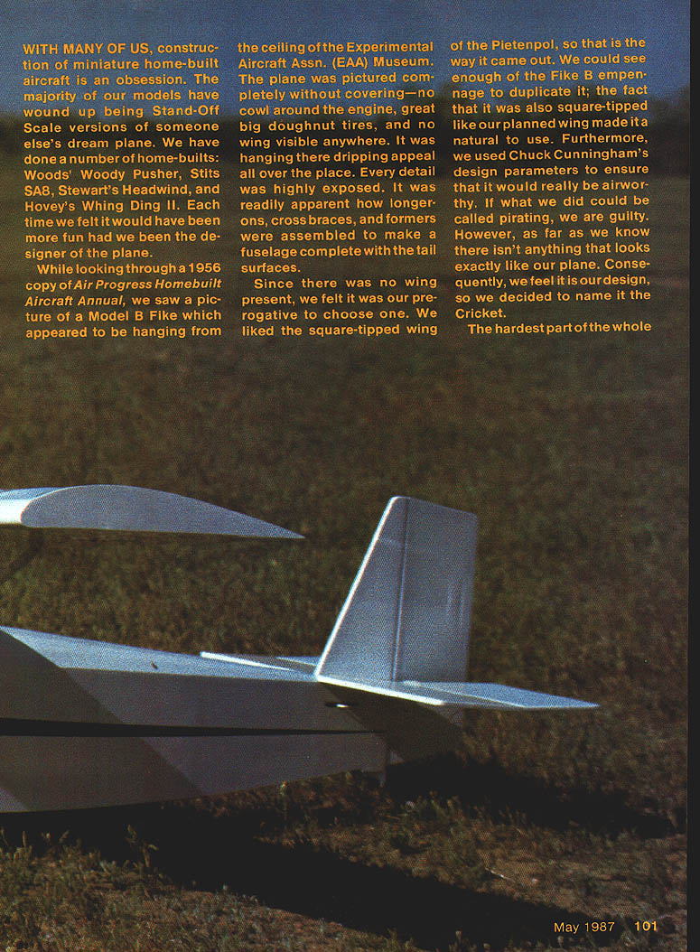
- Wing: square‑tipped, Pietenpol influence.
- Empennage: Fike B style, square‑tipped.
- Controls: three‑channel (rudder, elevator, throttle), optional ailerons for aileron/4‑channel setup.
- Airfoil and dimensions:
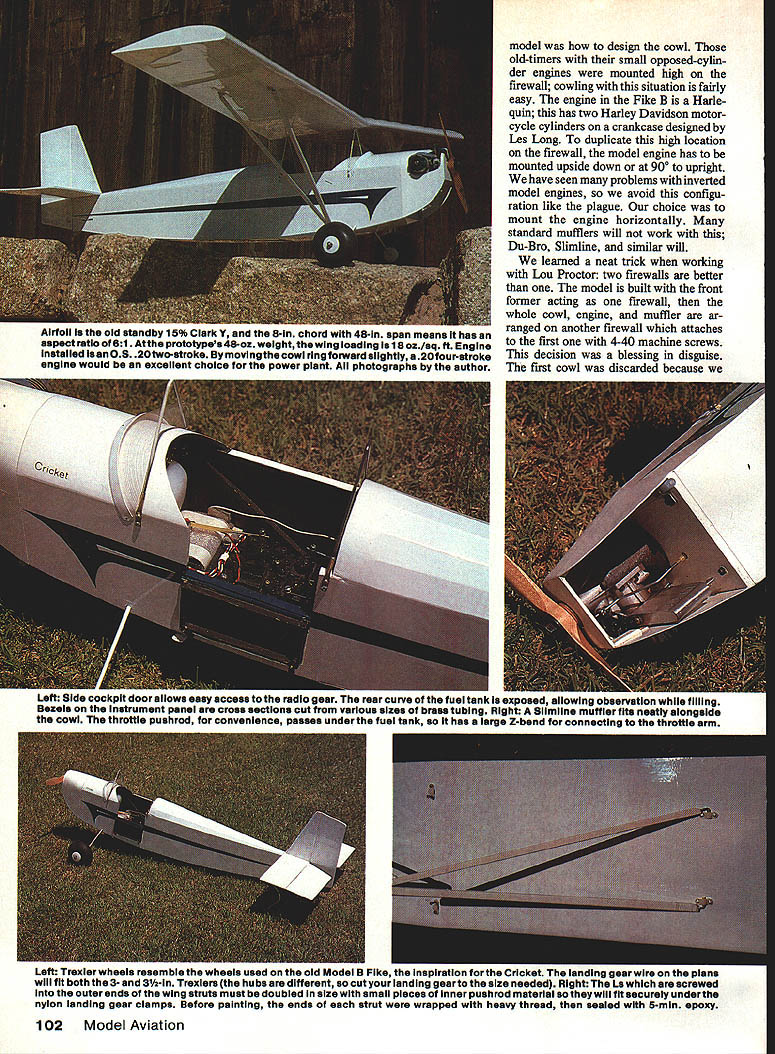
- Airfoil: 15% Clark Y
- Chord: 8 in
- Span: 48 in
- Aspect ratio: 6:1
- Prototype weight: ~48 oz
- Wing loading: ~18 oz/sq ft
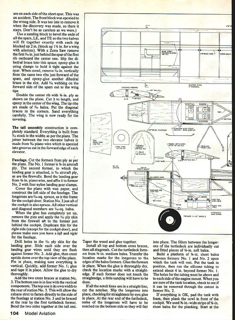
Cowl and firewall
The most difficult part of the project proved to be the cowl. The following practices were used:
- Engine mounting:
- Prefer mounting the model engine horizontally. Inverted engines have often presented problems and are avoided.
- Standard mufflers may not work; Du‑Bro Slimline (or similar slim mufflers) fit neatly alongside the cowl.
- Two‑firewall trick (learned from Lou Proctor):
- Build the front former to act as the primary firewall for the fuselage.
- Build a separate firewall that carries the engine/muffler/cowl assembly and attaches to the first with four 4‑40 machine screws and blind nuts.
- This allows easy removal/reworking of the cowl/engine installation without reconstructing the fuselage.
- Cowl ring and skin:
- Build the cowl ring from 1/8‑in aircraft plywood and support it with narrow 1/8‑lite ply strips while fitting.
- Bevel the cowl ring and firewall edges so 1/32‑in aircraft plywood cowl skin will glue flush.
- Use a paper pattern, cut and soak the 1/32 ply top skin in hot water for easier forming, then clamp and glue.
- Leave lower support at the bottom of the cowl ring removable for engine installation ease.
- Instrument bezels: cross sections cut from brass tubing.
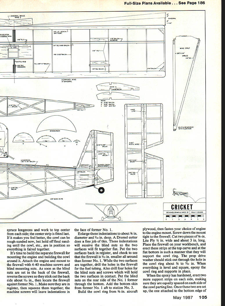
- Throttle: route the throttle pushrod under the fuel tank with a large Z‑bend to the throttle arm.
Tip: remove prop drive washer and needle valve during assembly; the engine will be in and out many times.
Landing gear and wheels
- Gear wire: bend landing gear from 3/32‑in music wire (or per plans).
- Wheels: Trexler wheels recommended; Cricket landing‑gear wire plans fit both 3‑in and 3‑1/2‑in Trexler hubs (cut gear to needed length).
- Bearings: drill wheel hubs with a 5/32‑in bit and insert 5/32‑in brass tubing bearings, add 1/8‑in wheel collars.
- Strut ends: wrap ends with heavy thread and seal with 5‑min epoxy to prevent splitting.
- Landing gear attachment: attach gear to former No. 2 with nylon landing‑gear clamps and screws as detailed on the plans.
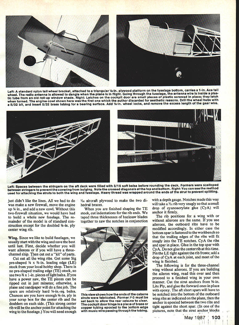
- Tailwheel: standard nylon tailwheel bracket attached to a triangular 1/4‑in plywood platform carrying a 1‑in Ace tailwheel.
Wing
Materials and preparation
- Ribs: cut from plan templates.
- Leading edge (LE): Sig pre‑shaped 3/4 x 5/8‑in stock (or equivalent).
- Trailing edge (TE): two 3/8 x 1‑in pieces of light balsa (or rip TE from stock with a power saw or plane and sandpaper).
- Spars: relatively hard 3/8‑in‑square balsa (some builders use 1/4‑in‑sq depending on personal preference).
- Center rib: double with 1/8‑in plywood doublers (strong center rib anchors wing to fuselage).
- Dihedral braces: two 1/16‑in aircraft plywood braces.
- Tip ribs: 3/16‑in balsa.
- Webbing: 1/16‑in sheeting on forward side of spars out to tips.
Building the wing
- Shape the TE stock and cut notches in TE for rib ends.
- Tape three thicknesses of hacksaw blades together to saw accurate notches for 3/32‑in ribs; a snug fit is desirable.
- A small drop of cyanoacrylate (CyA) will anchor ribs in place.
- Fasten bottom spar to the workbench so TE and ribs fit snugly into notches.
- CyA the ribs to the bottom spar in place, then glue the top spar. CyA the center rib (some sequences pin center rib later; follow the plans you are using).
- Pin the LE tight against rib fronts; add a drop of CyA at each joint.
- If building with ailerons: modify outboard ribs accordingly, cut and hinge ailerons and reinforce hinge lines.
- Bevel the ends of spar, LE and TE so the two wing halves fit together. Block up each tip 2 in (1‑1/4 in for aileron wing) when joining.
- Dihedral braces:
- Remove 1/16 in behind the spar of the first rib outboard of center, slip the dihedral brace into this space and epoxy.
- Repeat for the forward side, clamping until cured.
- Double the center rib with 1/8‑in ply and epoxy into the center of the wing.
- Add diagonal corner braces and sand smooth. The wing is then ready for covering.
Strut anchors and reinforcement (three‑channel wing without ailerons)
- Cut strut anchors from 3/8‑in lite ply and epoxy fore and rear anchors in place.
- Notch short spar tabs into the bottom rib of the outboard ribs as indicated on plans; epoxy anchor between ribs and tack against short spar.
- Sand underside true and install/epoxy dihedral braces.
Cabane, wing struts and anchors
- Cabane struts:
- Make from piano wire legs fitted into 1/8‑in brass tubing fittings.
- Tubing: cut four 1‑1/8‑in pieces of 1/8‑in brass tubing and four 5/8‑in pieces of 3/64‑in brass tubing as doublers for outer ends.
- Squeeze flush, insert piano‑wire legs, form an upside‑down V (lambda) and round ends with a ball‑peen hammer.
- Support posts: 1/8‑in ply, 5/8 in wide, 1‑1/8 in long; drill 1/8‑in holes and glue to cabin top.
- Tie installed cabane tubing to fuselage with safety wire wrapped and soldered.
- Wing struts:
- Make from 3/64‑in piano wire or 1/16‑in‑thick spruce strips (some builders use spruce with aluminum insert).
- Reinforce outer ends with short pieces of 1/8‑in brass tubing; slot inner ends and insert small sheet‑aluminum anchor plate, epoxy.
- Outer ends fasten under nylon landing‑gear clamps on outer wing anchors with small L‑hooks and inner Gold‑N‑Rod sleeves to bring diameter up to 1/8 in where needed.
- Underfuselage strut anchor:
- 3/8‑in strip of aluminum long enough to protrude 1/2 in on each side; drill holes for anchor screws, bolt to inside of fuselage and solder strut tubes in place.
Wing alignment and washout
- Assemble the skeleton plane (wing, cabane, struts, gear) for easier handling and to ensure screw holes are aligned.
- Mount wing and struts, then determine dihedral and washout:
- The two front struts set the dihedral; the rear struts determine washout.
- With the tail propped and fuselage level, measure from the workbench to the front corner and rear corner of each wing tip. Adjust L‑hooks to equalize distances and avoid warp.
- Leave the wing flat during covering, then add washout after covering:
- Put a 1/2‑in block under the outboard trailing edge corner while holding the wing center flat.
- This creates diagonal wrinkles in the film; iron out and shrink, then hold until cool.
- Final washout should be approximately 3/8 in at the tip.
Fuselage
Formers, longerons and skin
- Formers:
- Cut from ply per plans. Former No. 1: 1/8‑in aircraft ply. Former No. 2 (landing gear attachment): 3/16‑in aircraft ply. Firewalls: 3/16‑in ply.
- Longerons:
- 1/16‑in square spruce for main longerons and cockpit door frame. Station No. 3 just aft of cockpit is spruce. Other vertical/diagonal members are 3/16‑in‑sq balsa.
- Side construction:
- Cover plans with wax paper and build left side first.
- When glue has set, apply 1/32‑in ply skin from firewall aft to the former just behind the cockpit.
- Duplicate for the right side (except cockpit door) taking care to make distinct left and right halves.
- Landing gear fitting:
- Drill holes in 1/32 ply skin for landing gear, slide each side over gear wires until flush against former No. 2, glue and erect upside down over top view of plans.
- Cross braces and diagonals:
- Add two cross braces at station No. 3 (one in line with vertical components, the other set aft to receive cabane strut), then install top/bottom cross braces and diagonals.
- Turtledeck:
- Cut turtledeck formers from 1/8‑in medium balsa, transfer longeron location marks, glue formers and check with a straightedge. Sand where necessary and notch longerons to allow the turtledeck to flare into place.
- Fill gaps between longerons with individually fitted 1/8‑in soft balsa fillers.
Tank and cowl platform
- Build a platform of 1/8‑in sheet balsa between formers No. 1 and No. 2 to support the fuel tank.
- Route silicone tubing to extend about 4 in beyond former No. 1; tubing holes must be above and to each side of the engine mount.
- Pad tank with foam and check that it can be removed through the cutout in former No. 2 before final installation.
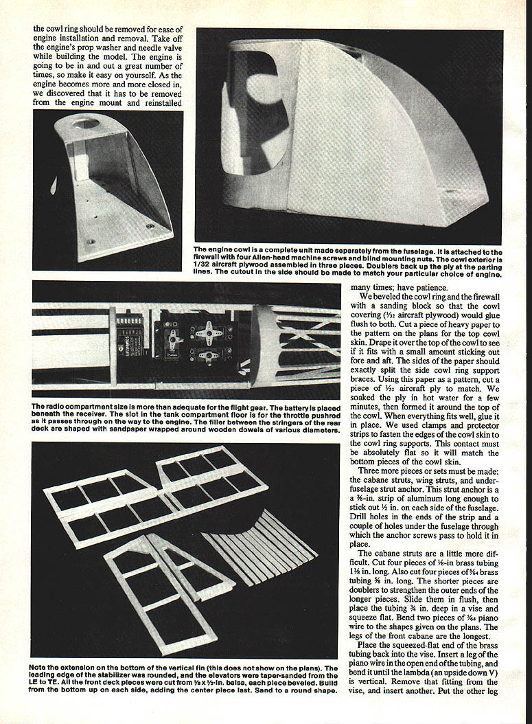
- Plank the cowl area in front of the cockpit with 3/8‑in‑wide strips of 1/8‑in sheet balsa, working from top center out each side and fitting the center strip last.
Firewall and engine mount
- Make the separate firewall that carries the engine mount and attaches to former No. 1 with 4‑40 machine screws and blind nuts.
- Before final assembly:
- Reverse the screws through the mount so they protrude slightly into former No. 1; use these to mark indentations for blind nuts.
- Enlarge indentations to ~3/16 in diameter and 1/16 in deep so blind nuts sit flush.
- Check that firewall is about 1/8 in smaller all around than former No. 1 so cowl skin will fair in.
- Drill fuel‑tubing holes and the four screw holes while surfaces are in register.
- Attach engine and mount with machine screws; the engine mount should be removable for service.
Tail assembly
- Standard construction from 3/16 stock sized per plans.
- Elevator joiner: 1/4‑in piano wire epoxied into forward grooves of each elevator half.
- Pin tail surfaces in place and fit pushrods from servos to facilitate locating horn positions before covering.
Covering and finishing
- Covering sequence:
- Cover turtledeck top first; cut and use pieces to cover the cowl and sides as needed.
- Cover bottom in two pieces starting at end of ply skin, overlapping about 3/16 in and working aft to tail.
- Allow covering to bend around former No. 1 about 1/2 in and seal; coat front of cockpit with epoxy for fuel proofing.
- Washout: put washout in after covering as described in Wing Alignment section.
- Painting:
- Cowl: two coats primer, two coats gloss white, one coat clear; paint back of firewall and inside cockpit flat black (two coats).
- Paint struts, rear ends of pushrods, landing gear, cabane struts and wheel hubs as desired.
- Cockpit hatch:
- Optional, made from 1/32‑in aircraft ply with an inside 1/4‑in‑sq balsa frame to make it flush. Overlap hatch 1/8 in each side.
- A length of 1/16 O.D. copper tubing with a piece of music wire can be used for hatch hinge/retention.
- Antenna: run antenna wire through a length of plastic tube so it dangles free in flight (old roll‑up window shade tube works well).
- Latches for cockpit door: small plastic pieces screwed in place.
Final assembly and flight preparation
- Fully assemble skeleton plane to confirm screw locations and alignment.
- Install wheels and check wheel bearings and collars.
- Balance model as shown on plans, check control throws and radio installation.
- Make a few glide tests before attempting powered flight.
- Recommended powerplants:
- .08–.20 two‑stroke
- A .20 four‑stroke works well if the cowl ring is moved forward slightly.
Notes and tips
- The two‑firewall arrangement permits trials and changes to the engine position or cowl without rebuilding the fuselage.
- Be careful when epoxying strut anchor blocks and positioning—one builder accidentally epoxied a block on the wrong side; check alignment before final glue.
- When fitting brass tubing into strut ends, clean, fit, and solder where required to prevent movement.
- Use clamps and protector strips when gluing thin ply skins to avoid crushing and to keep edges flat.
- After covering, check the tailplane and wing incidence and make final control adjustments.
End of article.
Transcribed from original scans by AI. Minor OCR errors may remain.

