
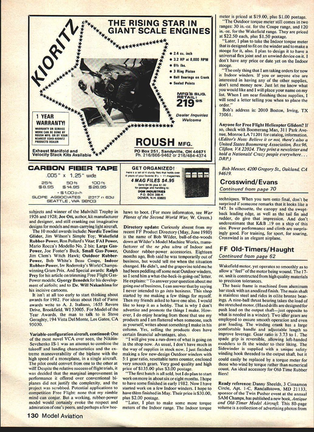
CROSSWIND
If long, relaxing flights are your thing, you'll like this semi-sailplane. It's the next generation of Bill Evans' Seville low-wing soarer, and with three channels and a K&B Veco .19 engine, it's the best of both worlds. Excellent takeoff and landing characteristics make it a great trainer; low sink and responsiveness make it a plane for two-pipe flights.
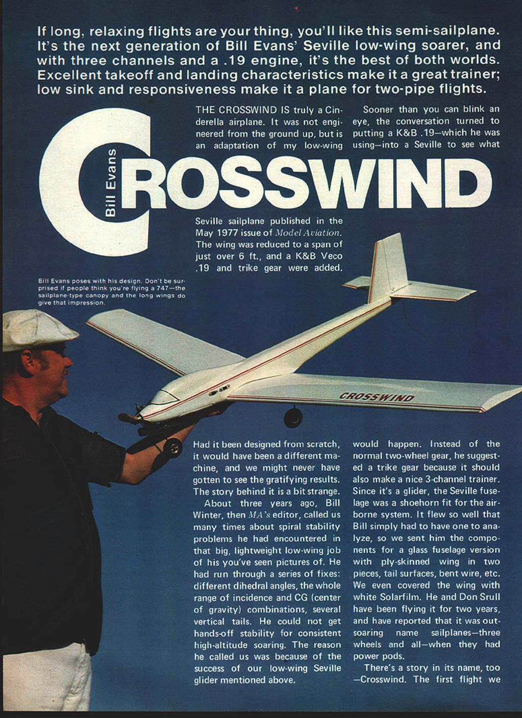
The Crosswind is truly a Cinderella airplane. It was not engineered from the ground up, but is an adaptation of my low‑wing Seville sailplane published in the May 1977 issue of Model Aviation. The wing was reduced to a span of just over 6 ft., and a K&B Veco .19 and trike gear were added.
Had it been designed from scratch, it would have been a different machine, and we might never have gotten to see the gratifying results. The story behind it is a bit strange.
About three years ago, Bill Winter, then MA's editor, called us many times about spiral stability problems he had encountered in that big, lightweight low‑wing job of his you've seen pictures of. He had run through a series of fixes: different dihedral angles, the whole range of incidence and center‑of‑gravity combinations, several vertical tails. He could not get hands‑off stability for consistent high‑altitude soaring. The reason he called us was because of the success of our low‑wing Seville glider mentioned above.
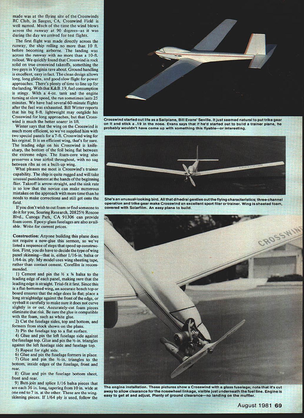
Sooner than you can blink an eye, the conversation turned to putting a K&B .19—which he was using—into a Seville to see what would happen. Instead of the normal two‑wheel gear, he suggested a trike gear because it should also make a nice three‑channel trainer. Since it's a glider, the Seville fuselage was a shoehorn fit for the airborne system. It flew so well that Bill simply had to have one to analyze, so we sent him the components for a glass fuselage version with ply‑skinned wing in two pieces, tail surfaces, bent wire, etc. We even covered the wing with white Solarfilm. He and Don Srull have been flying it for two years, and have reported that it was outsoaring name‑brand sailplanes—three wheels and all—when they had power pods.
There's a story in its name, too — Crosswind. The first flight we made was at the flying site of the Crosswinds RC Club, in Saugus, CA. Crosswind Field is well named. Much of the time the wind blows across the runway at 90 degrees—as it was during the day we arrived for test flights.
The first flight was made directly across the runway, the ship rolling no more than 10 ft. before becoming airborne. The landing was across the runway with no more than a 10‑ft. rollout. We quickly found that Crosswind is rock solid on true crosswind takeoffs, something the two guys in Virginia rave about. Ground handling is excellent, easy in fact. The clean design allows long, long glides, and good slow flight for power approaches. There's plenty of time to line up for the landing. With that K&B .19, fuel consumption is stingy. With a 4‑oz. tank and the engine turning at slow speed, the run sometimes lasts 25 minutes. We have had several 60‑minute flights after the fuel was exhausted. Bill Winter reports that his big 8‑ft. lightweight may outglide his Crosswind for long approaches, but that Crosswind is much the better soarer in lift.
Winter says that the wing on the Crosswind is much more efficient, so we've supplied him with two special panels for a 7‑ft. Crosswind wing for his original. It is an efficient wing, that's for sure. The leading edge on his Crosswind is knife‑sharp, the bottom of the foil being flat between the extreme edges. The foam‑core wing also preserves a true airfoil throughout, with no sag between ribs as on a built‑up wing.
What pleases me most is Crosswind's trainer capability. The ship is quite rugged and will take unusual punishment at the hands of the beginning flier. Takeoff is arrow‑straight, and the sink rate is so low that the novice can make numerous mistakes on the approach with more time than he needs to make corrections and still get onto the field.
If you don't wish to cut foam or find someone to do it for you, Soaring Research, 20825½ Roscoe Blvd., Canoga Park, CA 91306 can provide foam cores. Epoxy‑glass fuselages are also available. Write for current prices.
Construction
Anyone building this plane does not require a now‑glue sermon, so we've listed a sequence of steps that speed up construction. First, you do have to decide the type of wing panel skinning—that is, either 1/16‑in. balsa or 1/64‑in. ply. My model uses wing sheeting tape, rather than contact cement. Corefilm is recommended.
- Cement and pin the 1/2 x 3/4 balsa to the leading edge of each panel, making sure that the leading edge is straight. Trial‑fit it first. Since this is a flat‑bottomed wing, an accurate bench top or board ensures that the edge does lie flat; place a long straightedge against the front of the edge, or eyeball it carefully to make sure it does not curve slightly in or out. Accurately cut foam pieces eliminate that risk. Be sure the glue is compatible with the foam, such as white glue.
- Cut the fuselage sides, top and bottom, and formers from stock shown on the plans.
- Pin the fuselage top to a flat surface.
- Glue and pin the left fuselage side against the fuselage top. Glue and pin the 1/2‑in. triangles against the left fuselage side and fuselage top.
- Repeat for the right side.
- Glue and pin the fuselage formers in place.
- Glue and pin the 1/2‑in. triangles to the bottom, inside edges of the fuselage, front and rear.
- Glue and pin the fuselage bottom sheet, front and rear.
- Butt‑join and splice 1/16 balsa pieces that are each 36 in. long, tapering from 10 in. wide at one end to 7 in. at the other. These are the wing‑skinning pieces. If 1/64‑in. ply is used, follow the ply manufacturer's instructions for joining and splicing.
- Apply wing sheeting tape, following package instructions. By the way, this tape adds considerably to the spanwise strength of the wing, in that the bottom tape absorbs tension loads if the wing is bent upwards in a mishap, or in violent maneuvers and pullouts (not that there is any danger of in‑flight failure). The skin overlaps the leading edge — previously installed — and is glued to it.
- When you bond the skin in place, be sure to use wing cradles as a base (these are the leftover pieces from when the core was cut), on a true, flat surface. This is important if you are to hold accurately the 1/4‑in. washout in each panel. As you know, washout is accomplished by raising the wing trailing edge at the wing tip, in this case 1/4 in. above the normal position without washout.
- Trim and sand wing panels, and add 1/4‑in. tip plates.
- Glue and pin the 3/16‑in. balsa leading edge to each wing panel. Remember, a balsa leading edge, previously installed, butts against the top and bottom skins; this second edge provides for shaping the edge to airfoil contour.
- Join wing panels at the center line with 5‑minute epoxy, setting required dihedral with blocks beneath each tip as shown on the plans. If you've cut your own cores, make a trial fit before using epoxy. The center joint is reinforced with fiberglass tape.
- Cut out tail surfaces from straight‑grained 3/16‑in. sheet. Select a grain that does not bend easily, so that warps will not result. Rock‑hard wood is too heavy, mushy wood too flimsy. The proper grade is a slightly softish medium‑weight wood. Sand to shape and cut lightening holes. You can save wood by butt‑gluing another piece of 3/16 to the 3/16 x 4 so that the stabilizer and elevator can be cut in one piece.
- Carve and sand the fuselage to shape, then cut out the bottom hatch to the radio compartment. To make the hatch, first use a razor saw for the front and rear cross‑grain cuts. Then make the length cuts on a right angle through the 1/2‑in. triangle with an X‑Acto knife, using a ruler for a straightedge.
- Mark location of main gear blocks, and cut out the wing openings to accommodate them. Install blocks with 5‑minute epoxy.
Cover components and assemble the plane. Covering must be a low‑temperature iron‑on, such as Solarfilm, because of the foam cores. If you use a glass fuselage shell, it is painted white. With the glass shell, the stabilizer bond is improved by drilling small holes through the platform so that the epoxy used in joining will fill the holes for added strength.
Miscellaneous
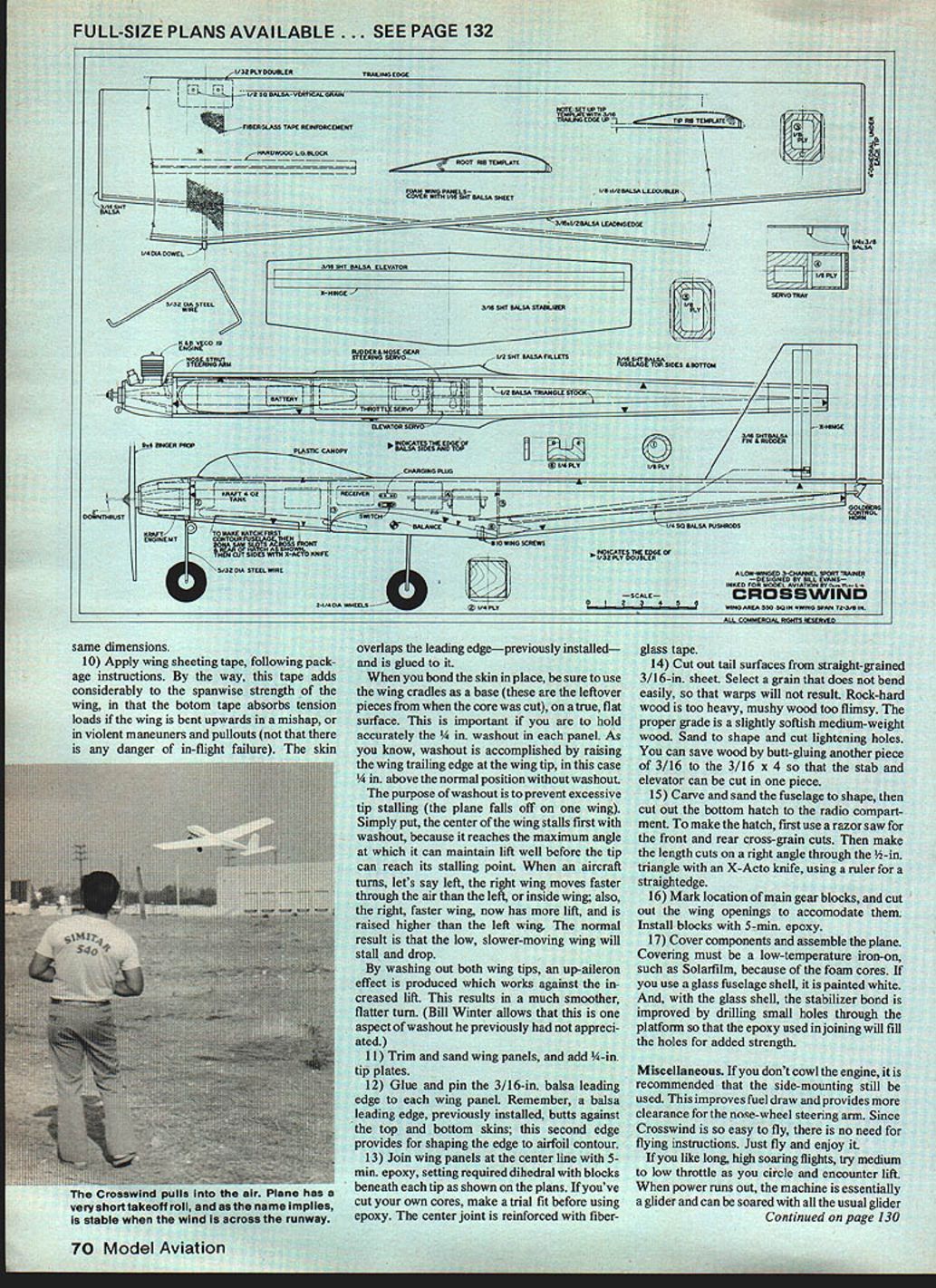
- If you don't cowl the engine, it is recommended that the side‑mounting still be used. This improves the field of view and provides more clearance for the nose‑wheel steering arm.
- Since Crosswind is so easy to fly, there is no need for flying instructions — just fly and enjoy it.
- If you like long, high soaring flights, try medium to low throttle as you circle and encounter lift. When power runs out, the machine is essentially a glider and can be soared with all the usual glider techniques.
When you turn onto final, don't be surprised if someone remarks that it looks like a 747. In silhouette, the canopy and the swept‑back leading edge, as well as the tail fin and rudder, do give that impression. And don't underestimate that K&B .19 on a ship of this size. Power performance and climb are surprisingly good. For training, for sport, for soaring, Crosswind is an elegant airplane.
Transcribed from original scans by AI. Minor OCR errors may remain.

