
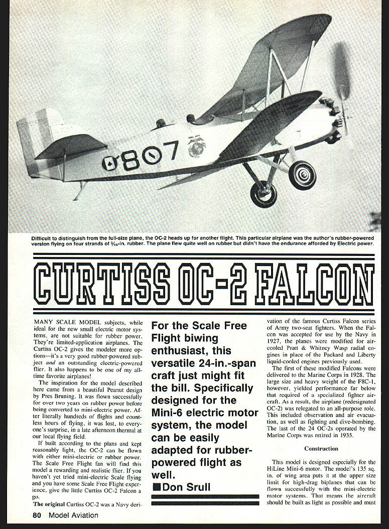
Curtiss OC-2 Falcon
Many scale-model subjects, while ideal for the new small electric motor systems, are not suitable for rubber power. They're limited-application airplanes. The Curtiss OC-2 gives the modeler more options — it's a very good rubber-powered subject and an outstanding electric-powered flier. It also happens to be one of my all-time favorite airplanes.
The inspiration for the model described here came from a beautiful Peanut design by Pres Bruning. It was flown successfully for over two years on rubber power before being converted to mini-electric power. After literally hundreds of flights and countless hours of flying, it was lost, to everyone's surprise, in a late-afternoon thermal at our local flying field.
If built according to the plans and kept reasonably light, the OC-2 can be flown with either mini-electric or rubber power. The Scale Free Flight fan will find this model a rewarding and realistic flier. If you haven't yet tried mini-electric scale flying and you have some Scale Free Flight experience, give the little Curtiss OC-2 Falcon a go.
For the Scale Free Flight biwing enthusiast, this versatile 24-in. span craft just might fit the bill. Specifically designed for the HiLine Mini-6 electric motor system, the model can be easily adapted for rubber-powered flight as well.
—Don Srull
The original Curtiss OC-2 was a Navy derivative of the famous Curtiss Falcon series of Army two-seat fighters. When the Falcon was accepted for use by the Navy in 1927, the planes were modified for air-cooled Pratt & Whitney Wasp radial engines in place of the Packard and Liberty liquid-cooled engines previously used.
The first of these modified Falcons were delivered to the Marine Corps in 1928. The large size and heavy weight of the F8C-1, however, yielded performance far below that required of a specialized fighter aircraft. As a result, the airplane (redesignated OC-2) was relegated to an all-purpose role that included observation and air evacuation, as well as fighting and dive-bombing. The last of the 24 OC-2s operated by the Marine Corps was retired in 1935.
Construction
This model is designed especially for the HiLine Mini-6 motor. The model's 135 sq. in. of wing area puts it at the upper size limit for high-drag biplanes that can be flown successfully with the mini-electric motor systems. That means the aircraft should be built as light as possible and must be properly trimmed to achieve optimum flight performance.
Except for wing spars and leading edges, use very lightweight balsa throughout. Also use firm, stiff balsa for fuselage longerons. Resist the temptation to beef up or reinforce the structure beyond what is adequate for its intended purpose.
Fuselage
- Build two identical sides using 3/32-in. sq. balsa. Join the two sides by adding crosspieces and formers.
- Bend cabane struts from .032-in. dia. piano wire and carefully glue them to formers F5 and F6 before attaching the formers to the fuselage frame.
- Make the landing gear legs from .045-in. piano wire and attach them to the bottom fuselage slotted crosspieces. Reinforce both the cabane and landing gear with small pieces of silk.
- Add 3/16 x 1/8-in. stringers. Complete the cockpit decking and nose sheeting.
- Carve the nose block (piece F1) to shape after facing it with 1/64-in. ply sheet. Make sure the cutout fits the HiLine motor.
- Ensure approximately 3° right thrust and 2° downthrust when the motor is mounted.
- Cover the landing gear legs with heavy paper fairings attached with white glue. Do not cover the cabane struts with paper fairings at this stage if you intend to fly the OC-2 on rubber power.
- If you may fly the model on rubber power later, install a rear motor-peg support now: glue a strip of 3/8-in.-wide, 1/32-in. sheet balsa at front fuselage upright section F1 so a 1/16-in. aluminum-tube rear motor peg can be added after the model is complete.
- Sand the fuselage structure, apply two coats of thin dope, and set aside until ready for covering.
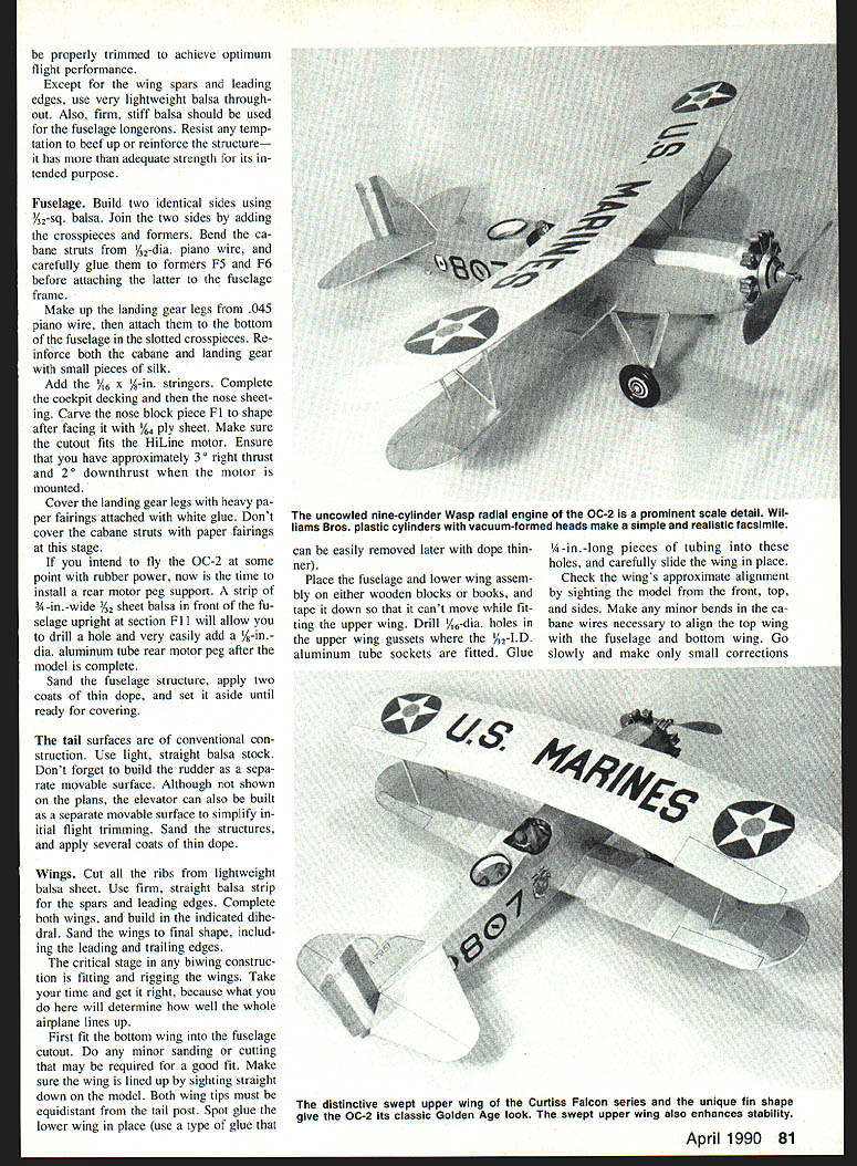
The uncowled nine-cylinder Wasp radial engine is a prominent scale detail. Williams Bros. plastic cylinders and vacuum-formed heads make a simple, realistic facsimile and can be removed later if required.
Tail surfaces
The tail surfaces are of conventional construction. Use light, straight balsa stock. Build the rudder as a separate movable surface. Although not shown on the plans, the elevator can also be built as a separate movable surface to simplify initial flight trimming. Sand the structures and apply several coats of thin dope.
Wings
- Cut all ribs from lightweight balsa sheet. Use firm, straight balsa strip for the spars and leading edges.
- Complete both wings and build in the indicated dihedral. Sand the wings to final shape, including the leading and trailing edges.
- Fitting and rigging the wings is critical. Take your time — correct alignment here determines overall performance.
- Fit the bottom wing into the fuselage cutout. Make minor sanding or cutting adjustments for a good fit. Sight down the model to check that both wing tips are equidistant from the tail post. Spot-glue the lower wing in place using a glue that can be removed later with dope thinner.
- Place the fuselage and lower-wing assembly on blocks or books and tape it down so it cannot move while fitting the upper wing.
- Drill holes in the upper-wing gussets and fit short lengths of aluminum tubing as wing socket inserts (use tubing sized to fit your cabane/interplane wires). Glue the tubing pieces in place and carefully slide the upper wing on.
- Check alignment by sighting the model from the front, top and sides. Make minor bends in the cabane wires as necessary; go slowly and make only small corrections.
- Final tweaks should bring the wings into perfect alignment when measured with rulers or pieces of thread.
Rigging and interplane struts
- With the top wing in place, add diagonal braces to the cabane. Do not omit these — they provide great strength and stiffness to the upper wing mount.
- Wrap thin steel or copper wire around the upper and lower ends of the cabane struts and spot-solder, or use Kevlar/heavy carpet thread fixed with CyA as an alternative.
- Make and fit the interplane struts: cut front and rear struts to size (left and right should match), add small metal pins to each end to reinforce the strut-to-wing joints, temporarily fit, then cut and glue the diagonal interplane strut. When dry these assemblies will be rigid and can be removed from the wings.
- Disassemble the model and add reinforcing gussets around the cabane attachment points. Attach heavy paper fairings around the cabane struts if desired.
Motor installation and battery
- Sheet a small area on the bottom of the fuselage between the landing gear legs with 3/32-in. balsa to accept the HiLine switch and charger plate; gluing these units from the inside will make them nearly flush with the bottom.
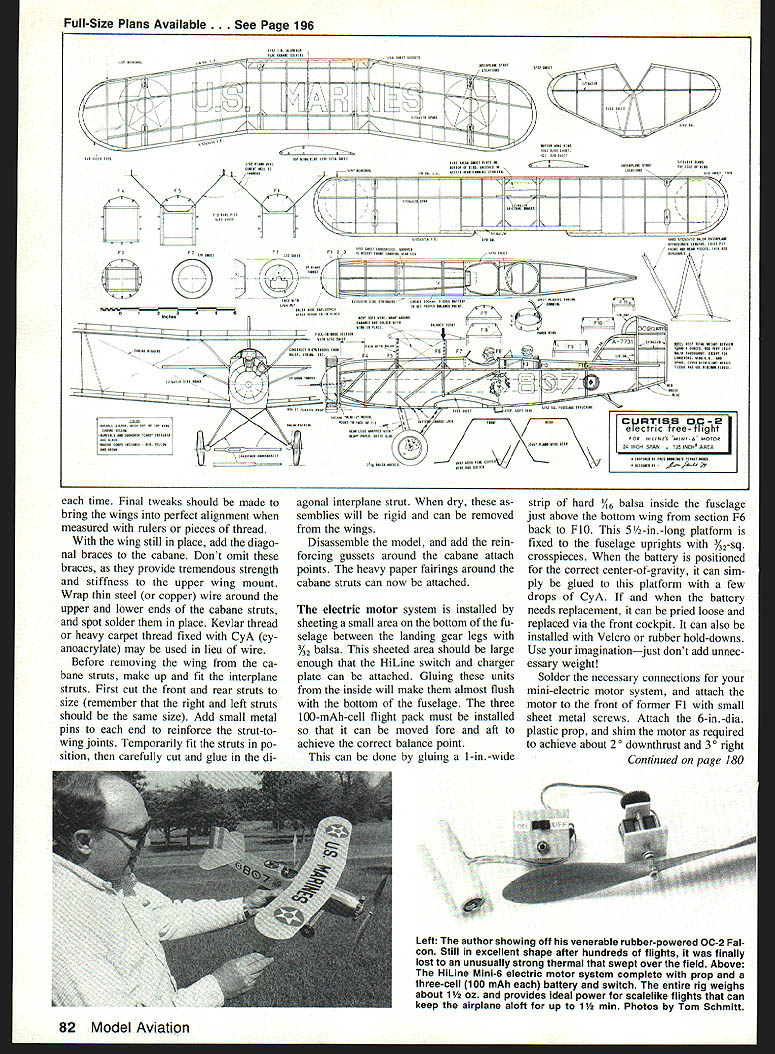
- Provide a movable battery platform so the three 100-mAh cells can be positioned fore and aft to achieve the correct balance point. One suggested method is to glue a 1-in.-wide strip of hard 1/16-in. balsa inside the fuselage just above the bottom wing from section F6 back to F10 to form a 5-1/2-in.-long platform supported by 3/32-in. sq. crosspieces.
- The battery can be fastened to the platform with a few drops of CyA, Velcro, or rubber hold-downs; make it replaceable via the front cockpit.
- Solder necessary connections for the mini-electric motor system and attach the motor to the front of former F1 with small sheet-metal screws. Attach a 6-in.-dia. plastic prop (or the recommended prop size for initial tests) and shim the motor to achieve about 3° right thrust and 2° downthrust.
Covering and finishing
- If dihedral prevents pinning the wings down in one piece, cover/shrink panel by panel.
- If small wrinkles remain, use a little water on the area rather than alcohol; if that fails, trim out and re-cover the problem area.
- When covering is satisfactory, apply two or three coats of a low-shrink dope (Sig Litrecoat or similar). Lightly fog on a coat of aluminum butyrate with an airbrush for aluminum surfaces; keep the finish light.
- Mask and spray registration numbers and U.S. Marine Corps markings on the upper wing. Cut masks from tracing paper and apply a light coat of 3M Scotch Spray Mount Adhesive to hold them in place.
- For complex emblems (Marine Corps logo, Ace of Spades squadron emblem), draw and paint them on tissue paper, cut them out, and adhere with double-sided tape or white glue.
Engine detailing
- Start with Williams Bros. plastic cylinders or make cylinders from paper tubes wrapped with string to simulate cooling fins. Carve or form cylinder heads and valve covers from balsa scraps or plastic.
- One method is to build a master cylinder head and vacuum-form nine identical heads from it, then mount them on paper cylinders and paint black and gunmetal.
- Mount the completed cylinders in equally spaced holes cut in F1, add wire pushrods, and fit the balsa nose piece after final flight trimming and thrust adjustments.
Wheels and crew figures
- If appropriate wheels aren't available, turn balsa wheels: laminate 1/4-in. balsa sheet on each side of a 1/32-in. ply disk (1-1/8-in. diameter), glue a 1/8-in. dowel through the hub, chuck in a drill, and sand/shape to form the wheel.
- Carve pilot and observer figures from balsa or foam. Add surface details with a technical pen or small waterproof felt-tip pen.
Assembly and flying
- Assemble the model, checking that all flying surfaces line up properly. Use white glue or an airplane-type glue; small spots of CyA provide a lighter bond and ease disassembly for repairs.
- After adding interplane struts, stabilizer struts, and landing gear wires, prepare for flight testing.
- Preflight: check all flying surfaces for warps and correct them; check the balance point and position the battery to the center-of-gravity shown on the plans (the rear cabane strut is a good reference).
- Test flying should be in calm weather over soft ground (tall grass). Begin with hand glides to identify major trim problems: ensure the model does not turn sharply, stall, or dive.
- Make small tail adjustments to correct glide tendencies. A slow, straight, somewhat mushy glide is desirable at this stage.
- For first powered tests, use short low-power runs (charge battery for a 15–20 second motor run). A small test prop (for example, a 4-1/4-in. or similar-size Williams Bros. prop) will provide enough thrust for an extended power glide or short level flight while trimming.
- Make slight adjustments to rudder and tail as required during these low-power flights. When satisfied, extend motor runs and refine trimming.
If built carefully and kept light, the Curtiss OC-2 Falcon is a rewarding scale model that flies very much like the original. Don't be timid — this little ship is a terrific flier and will look impressive in the air.
Transcribed from original scans by AI. Minor OCR errors may remain.

