
Curtiss Seahawk XF7C-3
Bill Darkow and John Hall
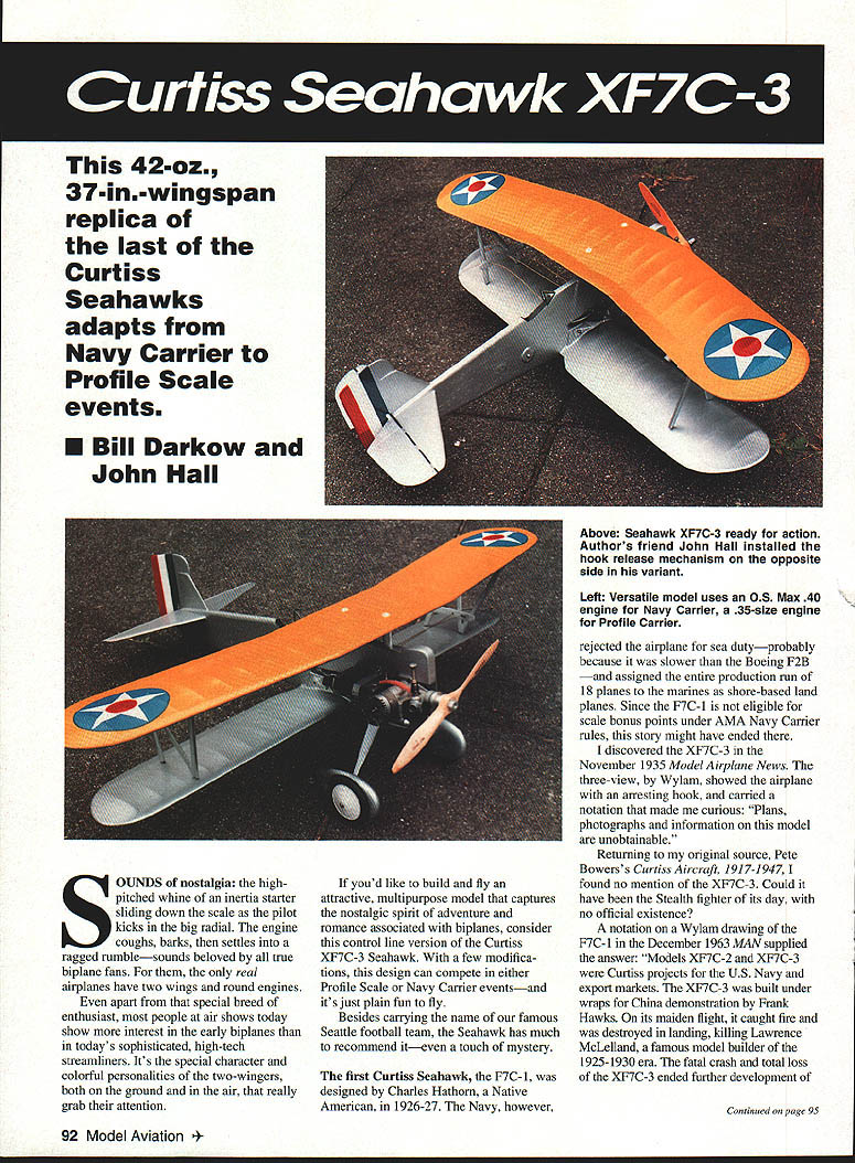
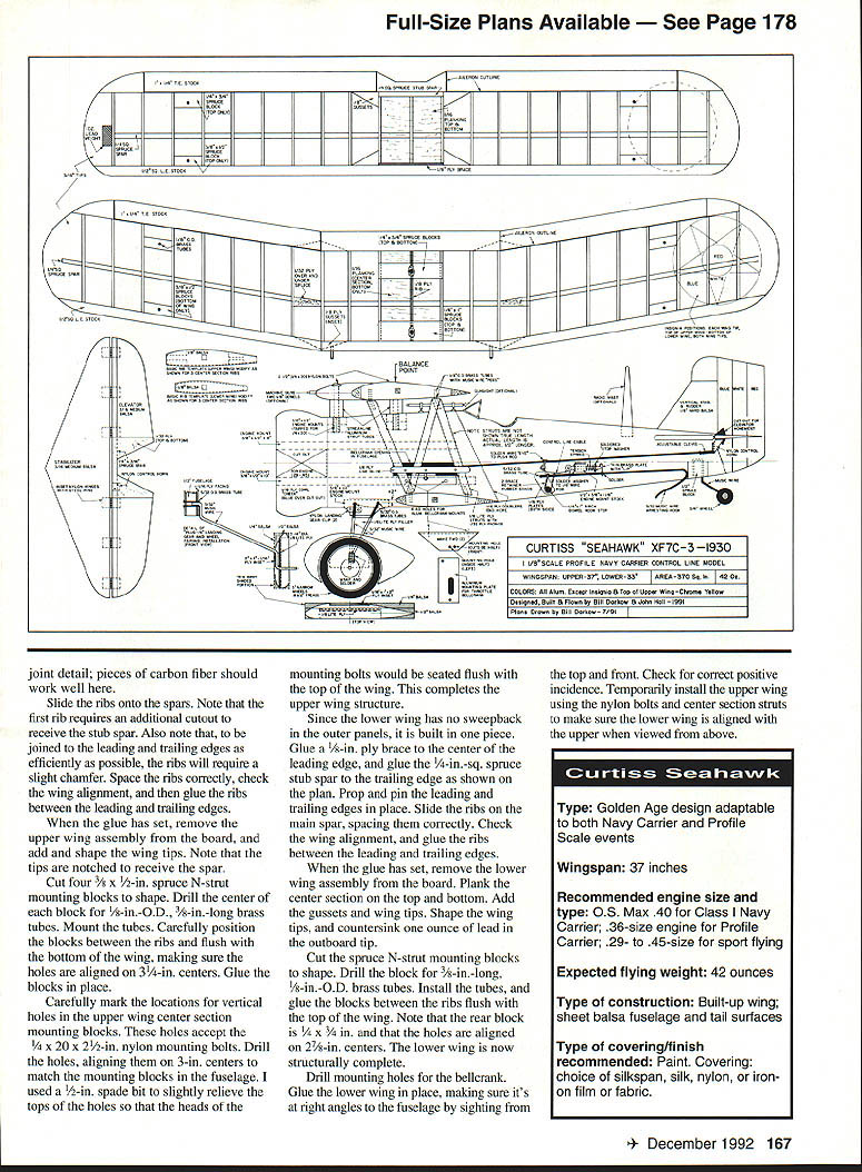
This 42-oz., 37-in. wingspan replica of the last of the Curtiss Seahawks adapts from Navy Carrier to Profile Scale events.
SOUNDS of nostalgia: the high-pitched whine of an inertia starter sliding down the scale as the pilot kicks in the big radial. The engine coughs, barks, then settles into a ragged rumble—sounds beloved by all true biplane fans. For them, the only real airplanes have two wings and round engines.
Even apart from that special breed of enthusiast, most people at air shows today show more interest in the early biplanes than in today's sophisticated, high-tech streamliners. It's the special character and colorful personalities of the two-wingers, both on the ground and in the air, that really grab their attention.
If you'd like to build and fly an attractive, multipurpose model that captures the nostalgic spirit of adventure and romance associated with biplanes, consider this control line version of the Curtiss XF7C-3 Seahawk. With a few modifications, this design can compete in either Profile Scale or Navy Carrier events—and it's just plain fun to fly.
Besides carrying the name of our famous Seattle football team, the Seahawk has much to recommend it—even a touch of mystery.
The first Curtiss Seahawk, the F7C-1, was designed by Charles Hathorn, a Native American, in 1926–27. The Navy, however, rejected the airplane for sea duty—probably because it was slower than the Boeing F2B—and assigned the entire production run of 18 planes to the Marines as shore-based land planes. Since the F7C-1 is not eligible for scale bonus points under AMA Navy Carrier rules, this story might have ended there.
I discovered the XF7C-3 in the November 1935 Model Airplane News. The three-view, by Wylam, showed the airplane with an arresting hook, and carried a notation that made me curious: "Plans, photographs and information on this model are unobtainable."
Returning to my original source, Pete Bowers's Curtiss Aircraft, 1917–1947, I found no mention of the XF7C-3. Could it have been the stealth fighter of its day, with no official existence?
A notation on a Wylam drawing of the F7C-1 in the December 1963 MAN supplied the answer: "Models XF7C-2 and XF7C-3 were Curtiss projects for the U.S. Navy and export markets. The XF7C-3 was built under wraps for China demonstration by Frank Hawks. On its maiden flight it caught fire and was destroyed in landing, killing Lawrence McLelland, a famous model builder of the 1925–1930 era. The fatal crash and total loss of the XF7C-3 ended further development of the Seahawk series. Many design features reappeared on the F8C-4, XF10C-1 and F11C-1 (Helldiver and Goshawk). Apparently, the XF7C-3 was so secret that no official company records were available to Pete Bowers for reference in compiling his book. Furthermore, why was the airplane equipped for carrier operation even though China had no carriers? Makes you wonder what was going on."
If you'd like a copy of the three-view from the November 1935 Model Airplane News and the December 1963 MAN, an SASE to my address at the end of this article will get you one.
Construction
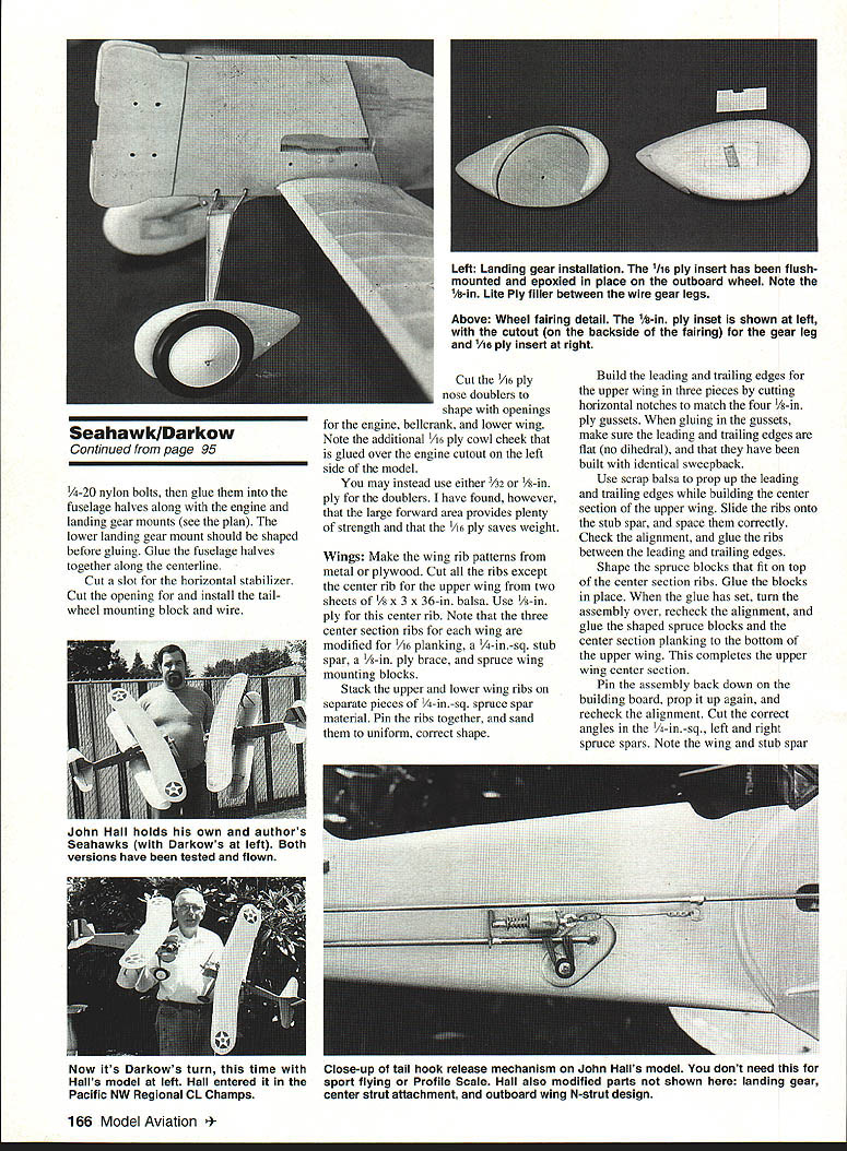
Two XF7C-3 prototype models have been thoroughly tested and flown. John Hall, a fellow Seattle Skyraider, finished his in time to compete in the Pacific Northwest Regional Control Line Championships at Eugene, Oregon. John's Seahawk didn't win, but its unique design attracted a lot of attention. Further refinement should make the model a contender.
As you might expect, John and I had differences of opinion about some of the features—chiefly the landing gear and wing strut design. My landing gear is truer to scale; John's is simpler. The center strut attachment on John's model is truer to scale; mine is simpler. We're still arguing over whose outboard strut design is easier to build, but mine is truer to scale.
A control line model of a Profile Scale biplane for Navy Carrier presented some unique challenges. Generally, we favored simplicity of construction over fidelity to scale, but we also took care to compromise scale accuracy as little as possible.
Fuselage
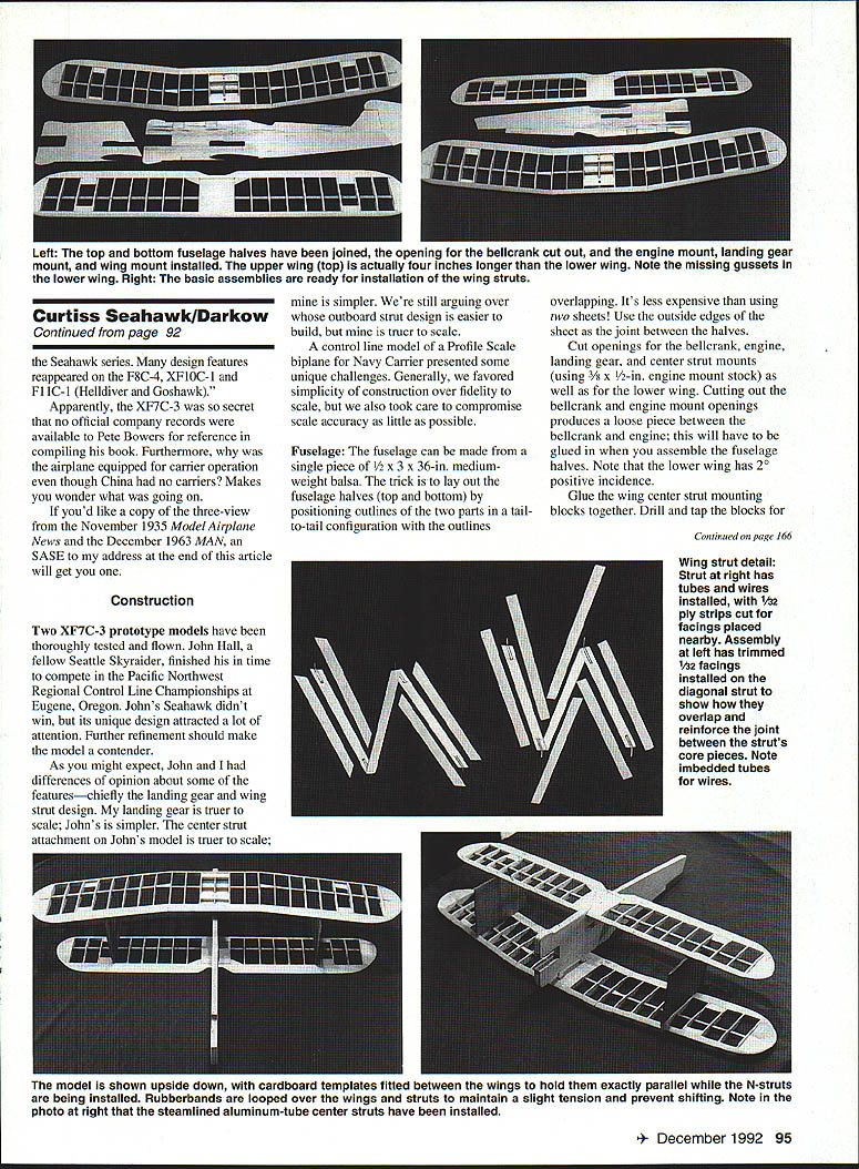
The fuselage can be made from a single piece of 1/2 x 3 x 36-in. medium-weight balsa. The trick is to lay out the fuselage halves (top and bottom) by positioning outlines of the two parts in a tail-to-tail configuration with the outlines overlapping. It's less expensive than using two sheets! Use the outside edges of the sheet as the joint between the halves.
Cut openings for the bellcrank, engine, landing gear, and center strut mounts (using 3/16 x 1/2-in. engine mount stock) as well as for the lower wing. Cutting out the bellcrank and engine mount openings produces a loose piece between the bellcrank and engine; this will have to be glued in after you assemble the fuselage halves. Note that the lower wing has 2° positive incidence.
Glue wing center strut mounting blocks together. Drill and tap the blocks for 1/4-20 nylon bolts, then glue them into the fuselage halves along with the engine and landing gear mounts (see the plan). The lower landing gear mount should be shaped before gluing. Glue the fuselage halves together along the centerline.
Cut a slot for the horizontal stabilizer. Cut the opening for and install the tailwheel mounting block and wire for the engine, bellcrank, and lower wing. Note the additional 1/16-in. ply cowl cheek that is glued over the engine cutout on the left side of the model.
You may instead use either 3/32- or 1/8-in. ply for the doublers. I have found, however, that the large forward area provides plenty of strength and that the 1/16-in. ply saves weight.
Wings
Make the wing rib patterns from metal or plywood. Cut all the ribs except the center rib for the upper wing from two sheets of 1/8 x 3 x 36-in. balsa. Use 1/8-in. ply for this center rib. Note that the three center section ribs for each wing are modified for 1/16-in. planking, a 1/4-in.-sq. stub spar, a 1/8-in. ply brace, and spruce wing mounting blocks.
Stack the upper and lower wing ribs on separate pieces of 1/4-in.-sq. spruce spar material. Pin the ribs together, and sand them to uniform, correct shape.
Build the leading and trailing edges for the upper wing in three pieces by cutting horizontal notches to match the four 1/8-in. ply gussets. When gluing in the gussets, make sure the leading and trailing edges are flat (no dihedral), and that they have been built with identical sweepback.
Use scrap balsa to prop up the leading and trailing edges while building the center section of the upper wing. Slide the ribs onto the stub spar, and space them correctly. Check the alignment, and glue the ribs between the leading and trailing edges.
Shape the spruce blocks that fit on top of the center section ribs. Glue the blocks in place. When the glue has set, turn the assembly over, recheck the alignment, and glue the shaped spruce blocks and the center section planking to the bottom of the upper wing. This completes the upper wing center section.
Pin the assembly back down on the building board, prop it up again, and recheck the alignment. Cut the correct angles in the 1/4-in.-sq. left and right spruce spars. Note the wing and stub spar joint detail; pieces of carbon fiber should work well here.
Slide the ribs onto the spars. Note that the first rib requires an additional cutout to receive the stub spar. Also note that, to be joined to the leading and trailing edges as efficiently as possible, the ribs will require a slight chamfer. Space the ribs correctly, check the wing alignment, and then glue the ribs between the leading and trailing edges.
When the glue has set, remove the upper wing assembly from the board, and add and shape the wing tips. Note that the tips are notched to receive the spar.
Cut four 3/8 x 1/2-in. spruce N-strut mounting blocks to shape. Drill the center of each block for 1/8-in. O.D., 3/8-in.-long brass tubes. Mount the tubes. Carefully position the blocks between the ribs and flush with the bottom of the wing, making sure the holes are aligned on 3-1/4-in. centers. Glue the blocks in place.
Carefully mark the locations for vertical holes in the upper wing center section mounting blocks. These holes accept the 1/4-20 x 2-1/2-in. nylon mounting bolts. Drill the holes, aligning them on 3-in. centers to match the mounting blocks in the fuselage. I used a 1/2-in. spade bit to slightly relieve the tops of the holes so that the heads of the mounting bolts would be seated flush with the top of the wing. This completes the upper wing structure.
Since the lower wing has no sweepback in the outer panels, it is built in one piece. Glue a 3/8-in. ply brace to the center of the leading edge, and glue the 1/4-in.-sq. spruce stub spar to the trailing edge as shown on the plan. Prop and pin the leading and trailing edges in place. Slide the ribs on the main spar, spacing them correctly. Check the wing alignment, and glue the ribs between the leading and trailing edges.
When the glue has set, remove the lower wing assembly from the board. Plank the center section on the top and bottom. Add the gussets and wing tips. Shape the wing tips, and countersink one ounce of lead in the outboard tip.
Cut the spruce N-strut mounting blocks to shape. Drill the block for 3/8-in.-long, 1/8-in. O.D. brass tubes. Install the tubes, and glue the blocks between the ribs flush with the top of the wing. Note that the rear block is 1/4-in. wide and that the holes are aligned on 2-3/8-in. centers. The lower wing is now structurally complete.
Drill mounting holes for the bellcrank. Glue the lower wing in place, making sure it's at right angles to the fuselage by sighting from the top and front. Check for correct positive incidence. Temporarily install the upper wing using the nylon bolts and center section struts to make sure the lower wing is aligned with the upper when viewed from above.
Wing struts
The center section struts are simply two short pieces of standard 5/8-in. streamlined aluminum strut tubing, readily available at any well-stocked hobby shop. Cut the struts to length as shown, and shape them to fit the wing camber. I glued 1/32-in. ply pads on the bottom of the upper wing as additional bearing for the struts. The upper wing should be at 0° incidence when installed with the nylon bolts tightened. The incidence can be adjusted either by inserting shims or by slightly changing the length of the struts.
The N-struts are easier to build than to describe. With both wings installed, cut a pair of matching cardboard templates to fit between the wings or to slide over the wing tips. These templates are needed to keep the wings exactly parallel while you fit the N-struts. Loop rubber bands over the wings and templates to maintain a tight tension and prevent shifting while the struts are being fitted.
Cut four 3/8-in.-wide upright struts from 1/8-in. Lite Ply, trimming each to fit between the strut mounting holes as shown on the plan. Cut 1/8-in.-wide, 1/2-in.-deep slots in the ends of each strut, and glue a piece of 1/2-in.-long, 1/8-in. O.D. brass tubing in each slot.
Cut eight 1-in.-long pieces of music wire to make a slip fit inside the tubes. Bend each piece of wire slightly in the middle, and, holding the strut in place, fit the wire in each end of the struts and in the proper mounting holes in the wings. The wings should flex enough to permit this operation. The wires are floating freely in the tubes mounted in the struts and wings, so they will self-align.
When you have finished fitting all four upright struts (a little patience and care are called for here), recheck the wing alignment, then cut and fit the 1/8-in. Lite Ply diagonal struts and glue them in place. All the N-struts should fit perfectly. Run the thin variety of Hot Stuff into the wire/tube joints on each strut to secure the wires.
Remove the N-struts, and glue 1/32-in. ply facings on each side. Overlap the upright/diagonal joint for strength.
An alternative method of securing the N-struts is to drill across each end of the upright struts, then bolt them to screw eyes or eye bolts in the mounting blocks. This method permits you to adjust the incidence, but unless a bent metal fitting is added to the ends of the N-struts to allow mounting them in the scale‑angled way, it's still easier to install them vertically. The upper N-strut mounting blocks would have to be moved one rib section inboard for the vertical installation.
Landing gear
Drill two 5/32-in. holes in the landing gear mount as shown on the plan. Install 3/8-in. lengths of 5/32-in. O.D. brass tubing in the holes. Bend four pieces of 3/32-in. music wire to shape as shown; I used a K&S Engineering Mini Wire Bender. Fit the landing gear wires in the tubes, mount them with nylon clamps, and wrap and solder them as shown. Install the 1/16-in. Lite Ply filler.
The wheel fairings are open-faced. Make them from 1/2-in. and 1/4-in. balsa glued together with a 1/8-in. ply insert and trimmed to shape. Notch the insides to receive the landing gear legs as shown on the plan. Epoxy the fairings in place, and cover the notch made for the landing gear wires with a piece of 1/16-in. ply. The cover should be a flush fit.
An alternative shaped aluminum landing gear is available for $10 from Tom Dixon, P.O. Box 671166, Marietta, GA 30066; order line: (404) 973-0004. Be sure to order the small profile gear. While the shaped aluminum gear are much simpler to mount to the fuselage, adding the wheel fairings becomes more complicated.
Bellcrank / Hook release
Cut and bend the bellcrank mounts to shape. Drill the mounts for the bellcrank, and fit the bellcrank in place. Assemble the bellcrank and mount on the model, and check for free operation. Throttle bellcranks are available from LR Products, Ltd., 7787 Archdale Ave., Detroit, MI 48228. Order the upright, short-span type.
Notch the fuselage for the hardwood block that carries the 1/8-in. hook release pin. Glue 1/32-in. ply plates to the fuselage, and drill the hole for the hook bearing and stop. The stop should limit the hook to a 45° angle when the hook is released. Install the bellcrank, pushrod, hook, and release mechanism after finishing the model.
Covering and finishing
Except for the chrome yellow top surface of the upper wing, the entire model is silver. Since the struts are separate from the upper wing, the yellow accent is easy to apply.
The wings can be covered with silkspan tissue, silk, nylon, or iron-on plastic or fabric. Subsequent finishing operations will depend on which material is chosen.
Add details such as the windshield (paint the cockpit black), guns, gunsight, radio mast, and aileron stripes. When the decorations are complete and the upper wing has been mounted, put Loctite or thin Hot Stuff in the wire/tube joints to help hold the struts in place.
Flying
For test-flying, balance the model as shown on the plan, or up to 1/2 in. further forward. Mount your engine as far forward as possible for best balance and maximum tank space. You can experiment with wing incidence and balance point settings for optimal performance under certain conditions. With slightly thicker, fully symmetrical airfoils on both wings, your Seahawk may even show some modest stunt performance.
For sport flying use 55- to 70-ft. control lines. See the AMA Competition Regulations handbook for recommendations on control line wire diameters, pull-testing, etc.
Happy flying! Address all correspondence to me at 1237 S. Grant St., Tacoma, WA 98405.
Transcribed from original scans by AI. Minor OCR errors may remain.

