
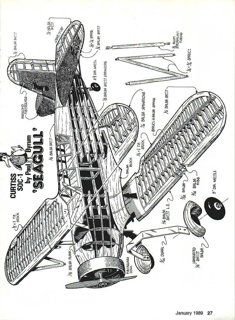
Curtiss SOC-1 Seagull
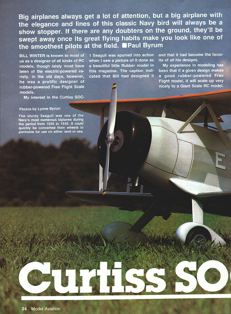
Big airplanes always get a lot of attention, but a big airplane with the elegance and lines of this classic Navy bird will always be a show stopper. If there are any doubters on the ground, they'll be swept away once its great flying habits make you look like one of the smoothest pilots at the field. — Paul Byrum
Overview
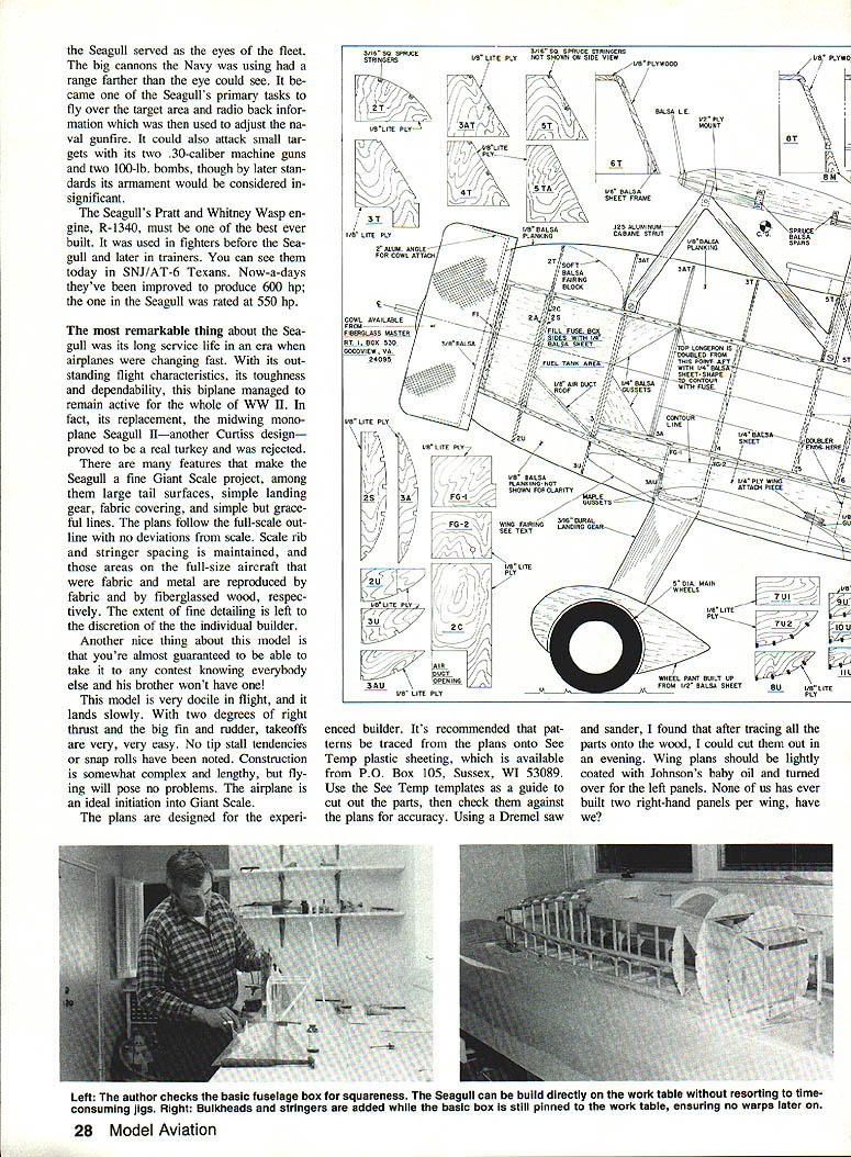
The Curtiss SOC-1 Seagull was a shipboard biplane scout that served as the "eyes of the fleet." Its primary tasks were to fly over target areas and radio back information used to adjust naval gunfire. It could also attack small targets with two .30-caliber Browning machine guns and carry two 100-lb bombs, although its armament became light by later standards. The Seagull was powered by the Pratt & Whitney Wasp R-1340 radial engine, rated at about 550 hp.
The Seagull's long service life is remarkable: in an era of rapid aeronautical change it remained in service through World War II because of its outstanding flight characteristics, toughness, and dependability. Its intended replacement, the midwing monoplane Seagull II (also a Curtiss design), proved disappointing and was rejected.
Why the Seagull makes a good Giant Scale project
- Large tail surfaces and simple landing gear.
- Fabric-covered surfaces and graceful, scale lines.
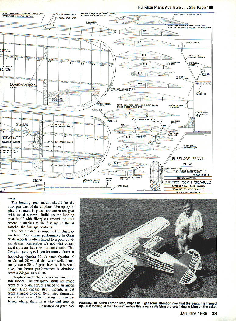
- Plans follow full-size outlines with no deviations from scale; rib and stringer spacing are maintained where used on the full-size aircraft.
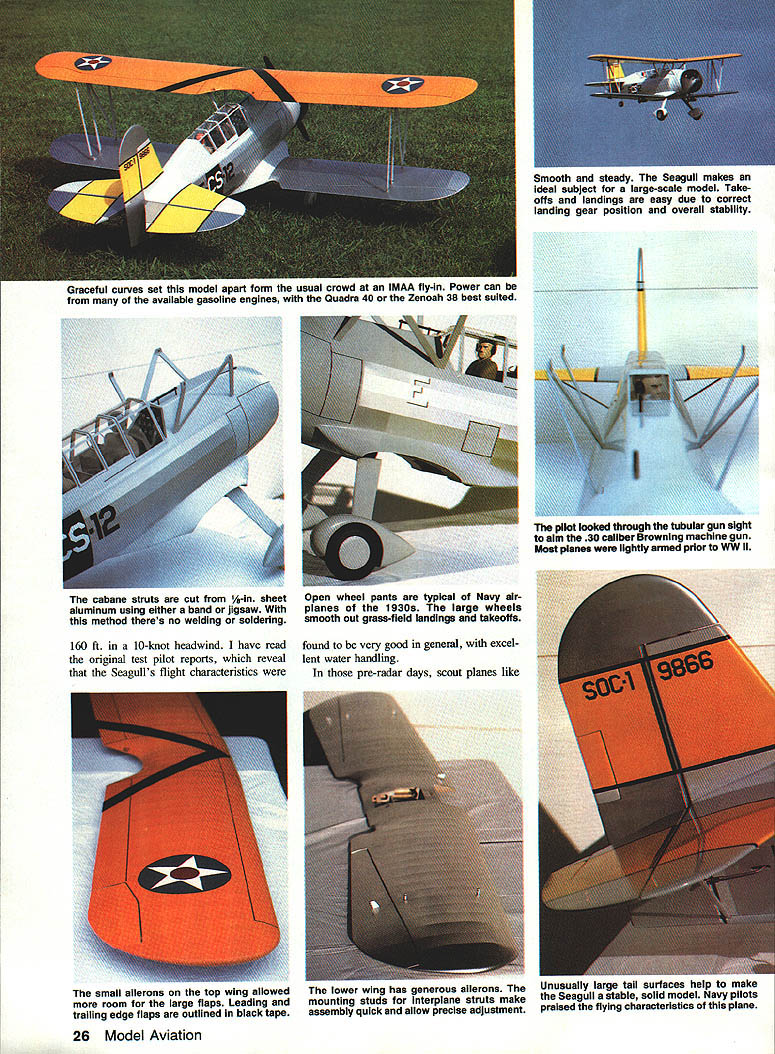
- The model is docile in flight, lands slowly, and has easy takeoffs with no noted tip-stall tendencies or snap rolls.
- Unique appearance: you’re unlikely to see many other models exactly like it at contests.
Construction is somewhat complex and lengthy, so the project is best suited to experienced builders. The plans are designed for experienced modelers; tracing patterns onto See-Temp plastic sheeting is recommended as a guide to cut out accurate parts.
Historical and flight characteristics
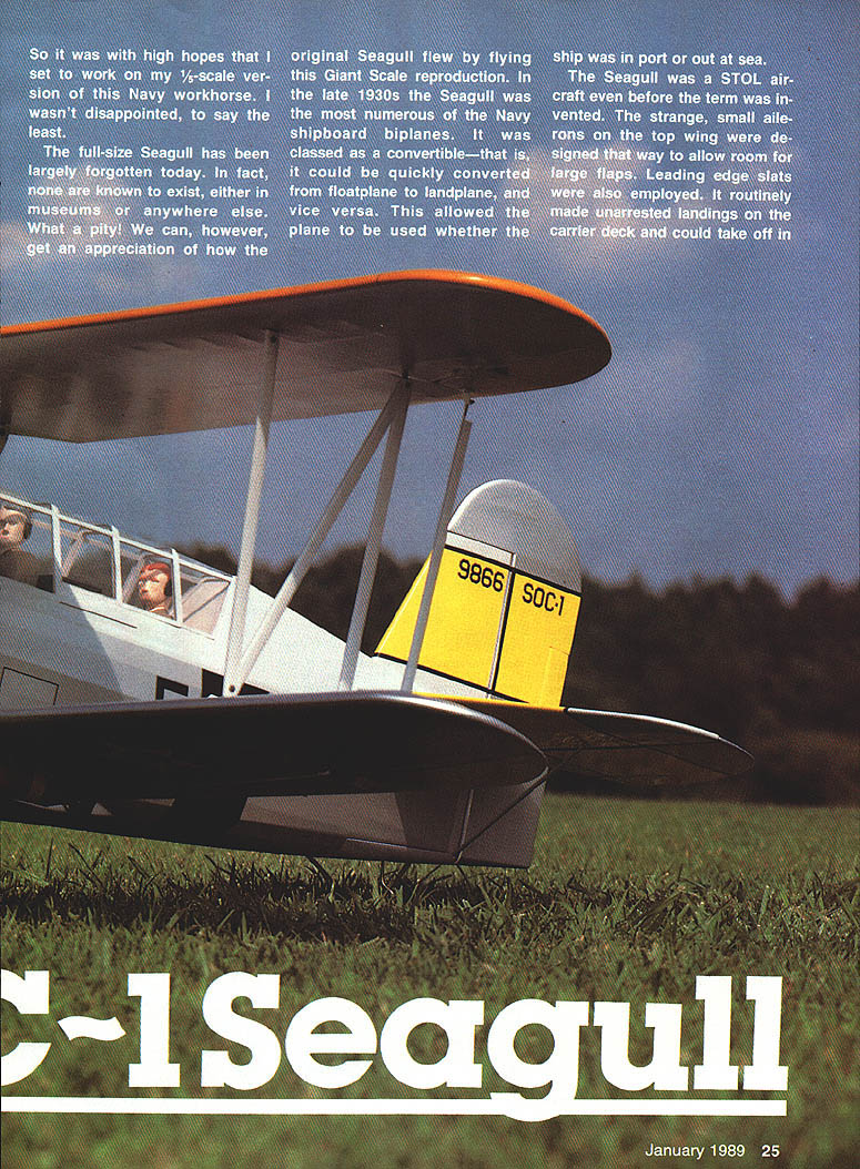
- The Seagull was classed as a convertible: it could be quickly changed from floatplane to landplane and vice versa.
- It featured STOL capability, leading-edge slats, large flaps, and small top-wing ailerons (designed to allow room for flaps).
- It routinely made unarrested landings on carrier decks and could take off in about 160 ft into a 10-knot headwind.
- Open-wheel "pants" and large wheels smoothed grass-field operations; the model demonstrates very good water-handling characteristics as well.
Plans, templates, and materials
It is recommended to trace patterns from the plans onto See-Temp plastic sheeting and use those templates to cut parts, then check against the plans for accuracy. Many parts can be sawed and sanded in an evening once traced.
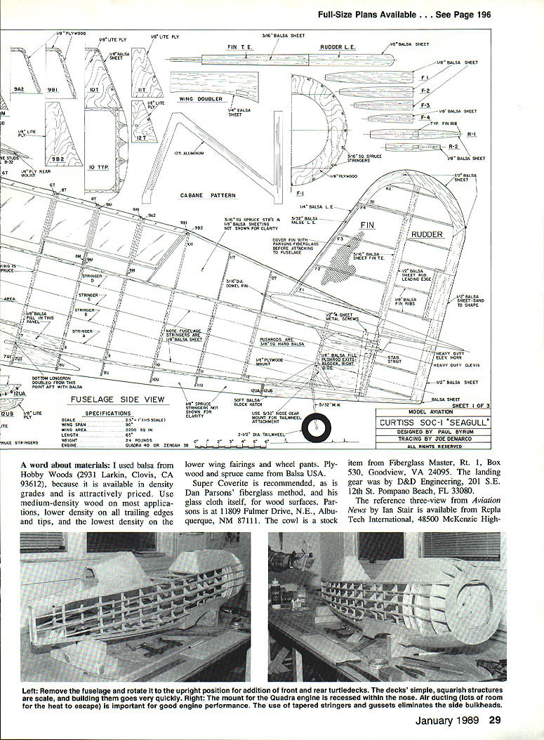
Materials and suppliers mentioned:
- See-Temp templates: See-Temp, P.O. Box 105, Sussex, WI 53089.
- Balsa (density-graded): Hobby Woods, 2931 Larkin, Clovis, CA 93612.
- Plywood and spruce: Balsa USA.
- Super Coverite (covering): recommended for open framework surfaces.
- Dan Parsons' fiberglass method and glass cloth: Dan Parsons, 11809 Fulmer Drive N.E., Albuquerque, NM 87111.
- Cowl (stock item): Fiberglass Master, Rt. 1, Box 530, Goodview, VA 24095.
- Landing gear: D&D Engineering, 201 S.E. 12th St., Pompano Beach, FL 33080.
- Reference three-view: Aviation News by Ian Stair available from Repla Tech International, 48500 McKenzie Highway, Vida, OR 97488.
- Hasegawa SOC-3 Seagull 1/72 plastic kit: useful as a visual reference.
- Bomb releases: Foremost bomb releases (use with a large, powerful servo).
- Profile Publication on the Seagull: out of print but sometimes available in libraries.
- Squadron/Signal Publications: Navy Air Colors, Vol. 1, by Doll, Jackson, and Riley.
- Decals: water-soluble types from Major (Major decals).
- Canopy glazing: .015 clear plastic from Sig.
- Canopy adhesive: Will-Hold's RC-56.
Construction
General notes:
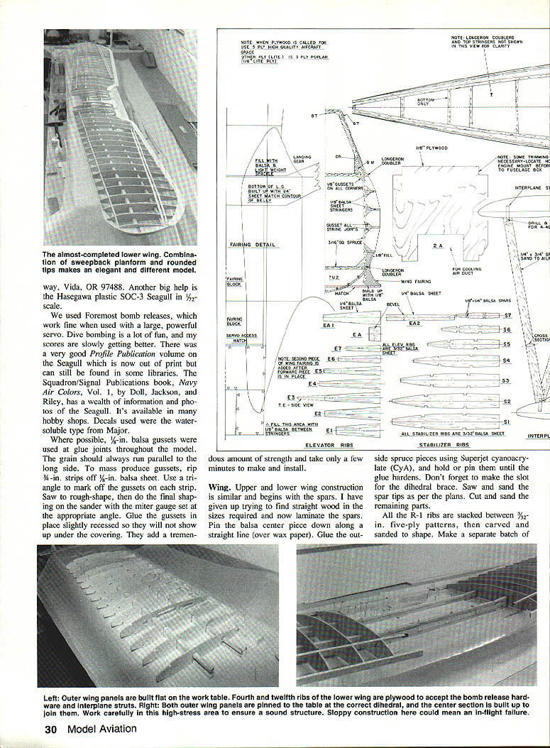
- Use 1/4-in. balsa gussets at glue joints where possible; grain should run parallel to the long side. To mass-produce gussets, rip 3/8-in. strips off 1/8-in. balsa sheet, mark triangles, rough-cut, then finish on a sander with the miter gauge set to the needed angle. Glue slightly recessed so they won’t show under covering.
- Laminate spars for straightness: pin the balsa center, glue spruce outside pieces with Superjet cyanoacrylate (CyA), and make the slot for the dihedral brace before final sanding.
- Save rib patterns and stack-cut ribs as indicated on the plans.
#### Wing
- Upper and lower wing construction is similar: begin with laminated spars, pin to the plan, and add ribs and spar strips.
- Mark and notch ribs for the 1/4 x 1/4-in. strips forming the wing/aileron separation.
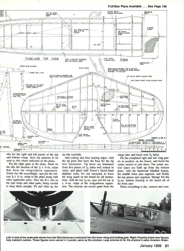
- Add trailing and false leading edges; build tip bow laminations from five pieces of 1/16-in. balsa, soaked and glued with an aliphatic resin (e.g., Tower's Quick-Sand).
- Add the top 3/16-sq. spar and the top 1/8 x 1/4-in. strips at the wing/aileron separation; ailerons are sawn apart later and faced with 3/32-in. balsa.
- Build right and left panels, then construct the center section to join them. Use hardwood dihedral braces and the middle balsa and top spruce spar segments.
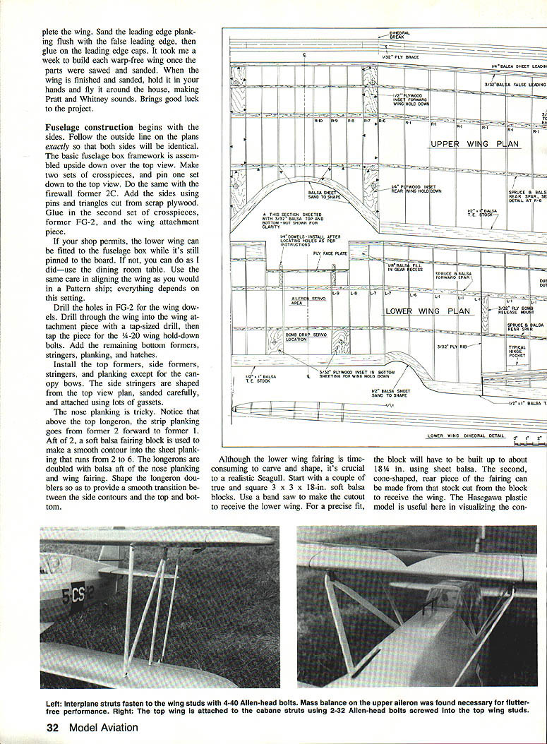
- Pin 3/32-in. bottom sheeting aft of the front spar while building; sand leading edge planking flush and glue on leading edge caps.
- Expect about a week per warp-free wing after parts are prepped.
#### Fuselage
- Build fuselage sides exactly to the plan so both sides match. Assemble the basic fuselage box framework upside down over the top view.
- Make two sets of crosspieces; pin one set down and add the firewall former 2C. Use pins and triangles cut from scrap plywood to hold sides.
- Drill holes in FG-2 for wing dowels; drill through the wing into the attachment piece with a tap-sized drill and tap for 1/4-20 hold-down bolts.
- Add remaining bottom formers, stringers, planking, and hatches. Install top formers, side formers, stringers, and planking except canopy bows.
- Longerons are doubled with balsa aft of the nose planking and wing fairing to provide smooth transitions.
- The nose planking: above the top longeron, strip planking runs from former 2 forward to former 1. A soft balsa fairing block aft of former 2 creates a smooth contour into sheet planking that runs from former 2 to 6.
Lower wing fairing:
- Time-consuming but crucial for realism. Start with square soft balsa blocks (3 x 3 x 18 in.), cut the wing cutout with a bandsaw, and build up to a precise fit with sheet balsa. The cone-shaped rear piece can be carved from that stock. The Hasegawa kit helps visualize the contours.
#### Landing gear
- The landing gear mount must be the strongest part of the airplane. Epoxy the mount in place and attach the gear with wood screws.
- Build up the landing gear with fiberglass around the attachment area so it matches fuselage contours.
- Landing gear components noted: D&D Engineering supplied the gear in the prototype.
#### Interplane and cabane struts
- Interplane struts: made from 1/4 x 3/8-in. spruce sanded to an airfoil shape.
- Cabane struts: cut from single pieces of 5/16-in. hard aluminum on a bandsaw; true edges with a file and straightedge.
- Studs: made from threaded steel rod screwed into tapped plywood securely glued inside the wings. Multiple laminations of 1/8- to 5/16-in. five-ply are preferable to a single thicker piece. Harden the tapped plywood with thin CA.
- Incidence can be adjusted by screwing the studs in or out. Drill and tap studs for screws that hold cabane and interplane struts; use Loctite on screws and epoxy studs in place once final alignment is achieved.
- Properly done, the model can be disassembled and assembled at the field in about 15 minutes.
#### Tail and control surfaces
- Stabilizer, fin, elevator, and rudder are built similarly: cut leading edges (LE) and trailing edges (TE) to plan dimensions, mark centerlines, pin over the plans, and glue ribs so centerlines meet.
- Sheet fin top side with 3/32 balsa, then turn over and sheet the other side.
- Stab spars are added after ribs; sheet stab with 1/16 balsa on both sides.
- Rudder and elevator ribs: 1/8 x 1-in. balsa tapered to meet the TE. Build directly over plans and cover with fabric as per the full-size Seagull.
- Use one servo per elevator to handle loads; with separate servos you can avoid joining the two elevator halves.
- Hinges: large Du-Bro type is recommended; follow hinge pocket locations on the plans and peg hinges with toothpicks for extra security. Many Giant Scale losses are due to unsuitable hinges—be careful!
- Aileron differential: about 20/80 down-to-up throw to avoid adverse yaw (if right aileron goes up 20°, left should go down about 5°). Two aileron servos are used; top and bottom ailerons are linked with a tie rod like the full-scale plane. External static balances on the ailerons were used on the prototype.
#### Canopy and cockpit
- The large canopy is a focal point but not problematic. Sand and prime parts before assembly.
- Use basswood stringers (available in model railroad sections) for canopy framing.
- After covering and priming the fuselage and finishing the cockpit interior, glaze the canopy with .015 clear plastic from Sig and bond with Will-Hold's RC-56.
Covering, fiberglass, and finishing
- Cover open framework with Super Coverite and prime with nitrate dope (sprayed on to avoid brush marks). The author used Sig Supercote clear nitrate dope, followed by colored butyrate dope. Apply several coats and rub down with steel wool; a magnet removes small steel particles left in the finish.
- Parsons brand fiberglass is used on stabilizer, fin, wing fairing, interplane struts, wheel pants, and wooden surfaces not covered by fabric. Dan Parsons supplies cloth and instructions; his method is lighter and easier than older polyester methods.
- Dan Parsons' glass cloth and method are recommended for wood surfaces.
Engine, cooling, and props
- Hot air ducting in the cowling is important for cooling; poor cowling design is often the cause of poor engine performance. Focus on outlet airflow as well as inlet.
- The prototype used a hopped-up Quadra 35 for good performance; a stock Quadra 40 or Zenoah 38 would also work well.
- Scale prop: 20 x 6 was used (scale size), but better performance may be achieved with a Zinger 18 x 6–10 depending on engine and tuning.
- Before flying, check the radio with the power off and the engine running at full throttle. Also do a power check using a smaller prop to approximate in-flight rpm.
Preflight, flying impressions, and trim
- The model is very docile and easy to trim. Two degrees right thrust and a large fin and rudder were used for initial trim.
- At 25 lb., the prototype Seagull took off in about 100 ft with no wind. Rudder response during takeoff was very good.
- Landing technique: hold the model a foot off the runway, apply more up elevator as it slows, and let it settle in. With practice, smooth landings are achievable.
- On the prototype, no tip-stall tendencies or snap rolls were observed. Aileron differential and static balancing helped achieve good handling.
Tips and shop techniques
- When laminating spars or building parts, pin over the plans and use wax paper to avoid sticking.
- Use medium-density balsa for most applications, lower density for trailing edges and tips, and the lowest density for lower wing fairings and wheel pants.
- To make gussets, rip strips from thin balsa and cut triangular pieces; shape on the sander with a miter gauge and glue slightly recessed.
- Use a Dremel saw and sander to cut out traced parts efficiently.
- For studs and tapped plywood, use a sharp tap to avoid splintering and saturate finished plywood with thin CA for strength.
- Use epoxy for structural glue joints where strength and gap-filling are needed; use CyA for laminations and quick joints as appropriate.
Acknowledgments and references
- The author acknowledges the interest and encouragement of Bill Winter, a prolific designer of rubber-powered free-flight scale models and recent electric RC designs.
- Research help from the library staff at the National Air and Space Museum, Washington, DC, was appreciated.
- References and helpful resources include:
- The Hasegawa SOC-3 Seagull 1/72 kit (visual reference).
- Profile Publication on the Seagull (out of print).
- Aviation News three-view by Ian Stair.
When this account was written, the author’s Seagull had 25 flights, each an emotional experience. The Seagull is a rewarding Giant Scale project for an experienced builder who wants an elegant, docile, and distinctive model.
Transcribed from original scans by AI. Minor OCR errors may remain.

