
The Curtiss-Wright
By Joseph S. Jessee
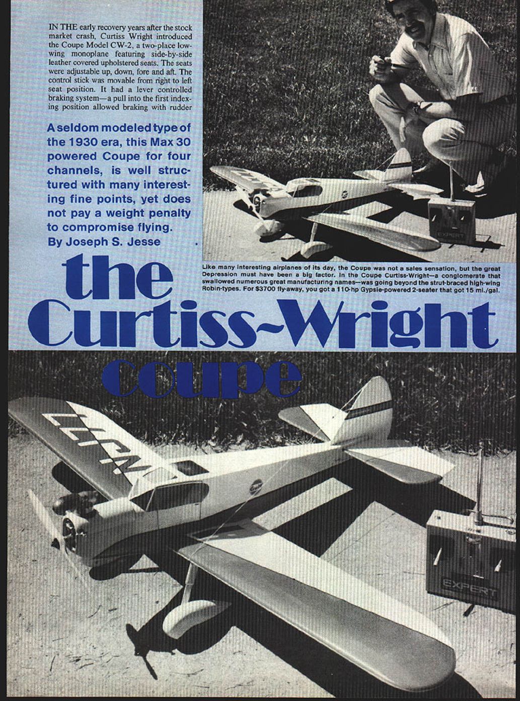
IN THE early recovery years after the stock market crash, Curtiss‑Wright introduced the Coupe Model CW‑2, a two‑place low‑wing monoplane featuring side‑by‑side leather‑covered upholstered seats. The seats were adjustable up, down, fore and aft. The control stick could be moved from the right to the left seat position. It had a lever‑controlled braking system — a pull into the first indexing position allowed braking with the rudder — pedals, and a left‑hand elevator trim for pitch adjustment.
A seldom‑modeled type of the 1930 era, this Max 30‑powered Coupe for four‑channel radio is well structured with many interesting fine points, yet does not carry a weight penalty that compromises flying.
The snugly enclosed cabin had excellent visibility in all directions except straight down and to the rear. A widely spaced landing gear and tail wheel provided good ground handling qualities.
It was powered by a 110 hp, 6‑cylinder in‑line Gypsy engine. At 1,700 rpm it cruised at about 110 mph and delivered roughly 15 miles per gallon. Rate of climb was 600 feet per minute.
It was introduced at the Detroit Air Show in 1931 with a fly‑away price of $3,700.
The Coupe was never a great commercial success although later versions attained some measure of popularity. One interesting similarity in later Coupe versions and the R/C version: laminated skin was used on experimental structural concepts. The strange part about the similarity is that my plans were about 90% complete before I received any background data.
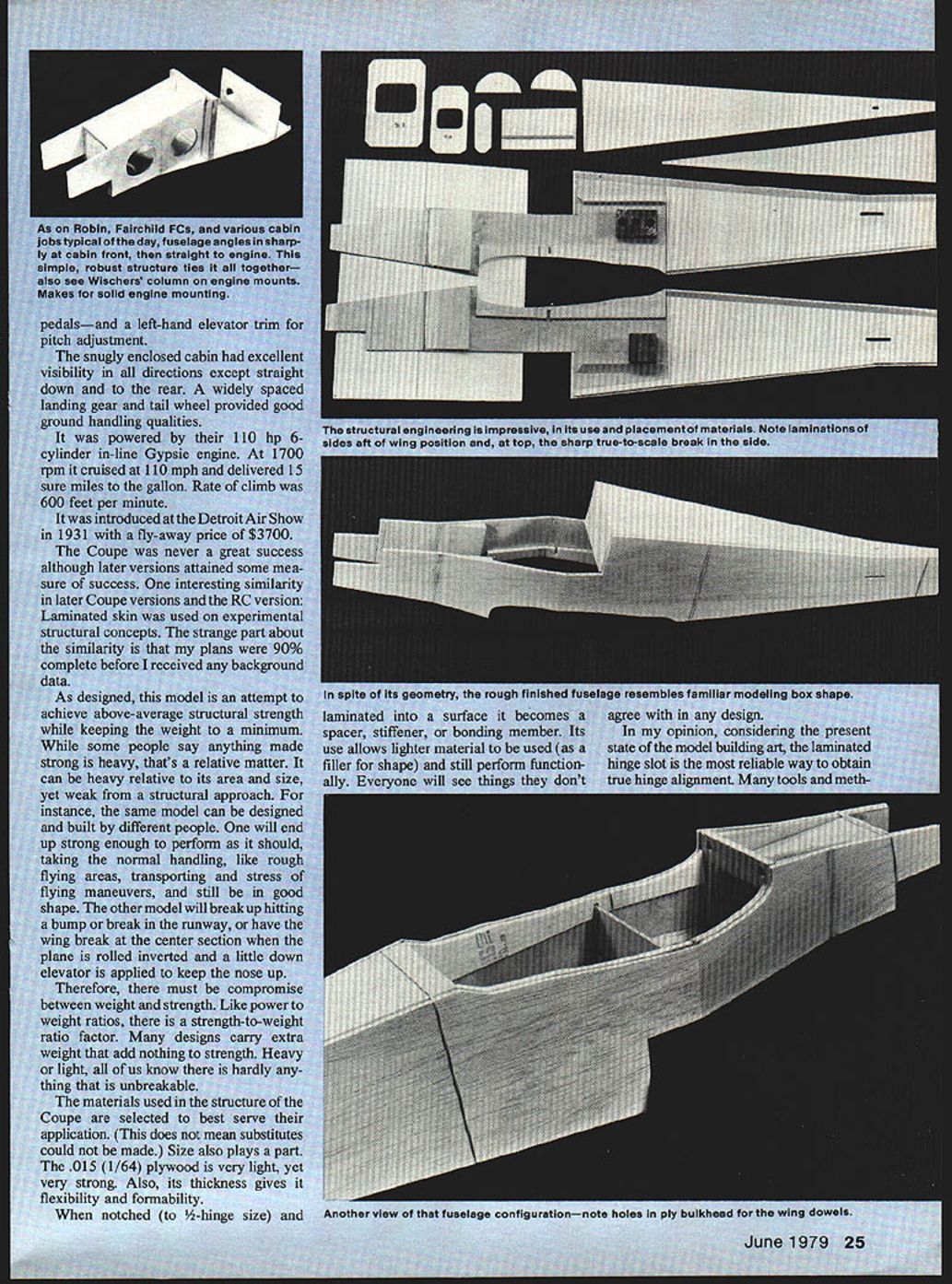
As designed, this model attempts to achieve above‑average structural strength while keeping weight to a minimum. While some people say anything made strong is heavy, that's relative. Something can be heavy for its size yet still be structurally weak. For instance, two builders can create the same model: one will end up strong enough to take normal handling, rough flying areas, transportation, and stress of maneuvers and remain in good shape; the other may break up hitting a bump, suffer a wing failure at the center section when rolled inverted with a little down elevator applied, or otherwise fail.
Therefore, there must be a compromise between weight and strength. Like power‑to‑weight, there is a strength‑to‑weight factor. Many designs carry extra weight that adds nothing to strength. Heavy or light, there is hardly anything that is unbreakable.
The materials used in the Coupe structure are selected to best serve their application (this does not mean substitutes cannot be made). Size also plays a part. The .015" (1/64") plywood is very light, yet very strong. Its thickness gives flexibility and formability.
When notched (to 1/2‑hinge size) and laminated into a surface it becomes a spacer, stiffener, or bonding member. Its use allows lighter material to be used as a filler for shape while still performing functionally. Everyone will see things they don't agree with in any design.
In my opinion, considering the present state of the model‑building art, the laminated hinge slot is the most reliable way to obtain true hinge alignment. Many tools and methods are used. If you wish to use tape hinges, make certain you have a good method to ensure straight alignment.
Laminating balsa stock (overview)
- Spot‑cement and cut four outer pant parts and two inner core parts.
- Epoxy parts together using thin coats on contacting surfaces; pin to ensure alignment.
- Clamp or use weights until parts dry. Use a template for shape.
- When dry, mark axle hole location. Remove paint build‑up before drilling.
- A Dremel drill stand is handy to get straight holes all the way through.
- Use nylon bushings in the pant axle holes (inside); cement a balsa cap on the outside and sand smooth.
- The axle should seat in dowel‑drilled bushings; use plywood washers centered over the axle holes inside.
- When shoes/skins are finished, prime and sand.
Materials and construction notes (key items)
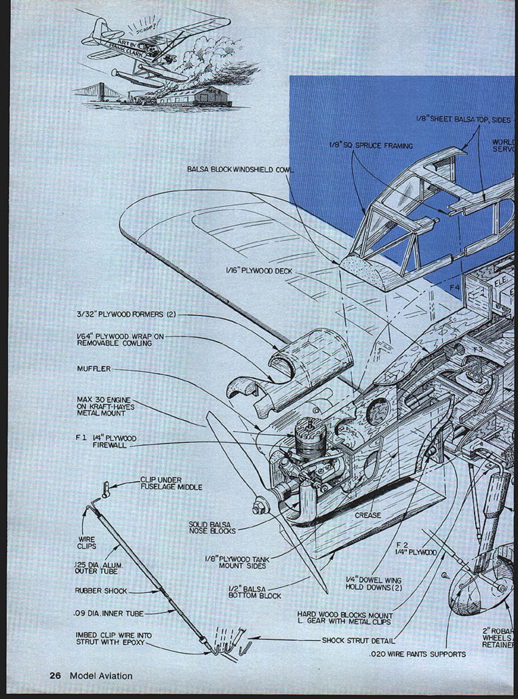
- Monofilament rigging through 1/4" dowel plugs
- 3/8" triangle stock all fuselage corners
- 1/16" sheet balsa doubled on all formers
- Wing mount screw‑through blocks
- F5, F6 (bulkhead references)
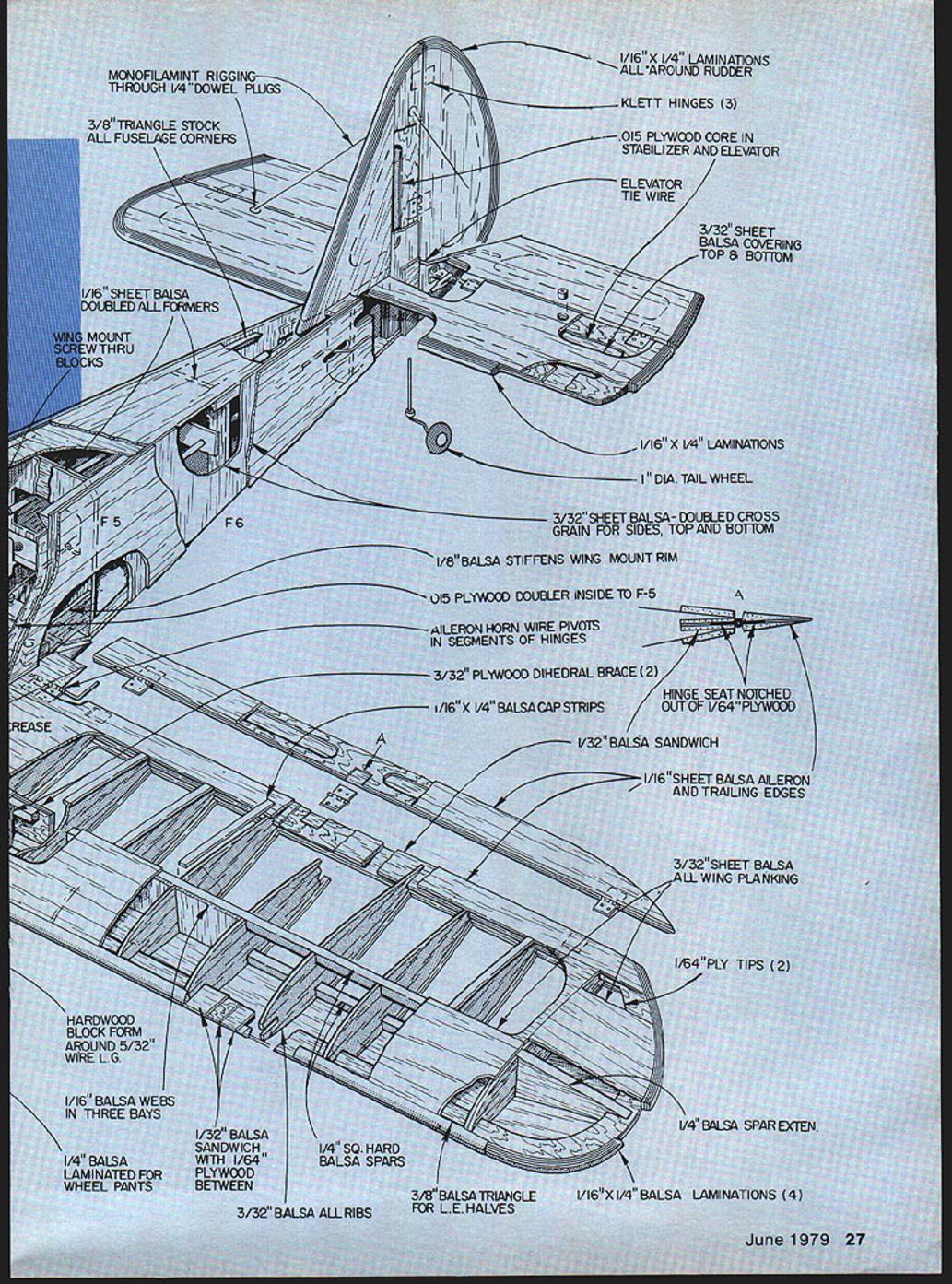
- 1/16" x 1/4" laminations all around rudder
- Klett hinges (3)
- .015" plywood core in stabilizer and elevator
- Elevator tie wire
- 3/32" sheet balsa covering top & bottom
- 1/16" x 1/4" laminations
- 1" diameter tail wheel
- 3/32" sheet balsa, doubled cross grain for sides, top and bottom
- 1/8" balsa stiffens wing mount rim
- .015" plywood doubler inside to F‑5
- Aileron horn wire pivots in segments of hinges
- 3/32" plywood dihedral brace (2)
- 1/16" x 1/4" balsa cap strips
- Hinge seat notched out of 1/64" plywood
- 1/32" balsa sandwich
- 1/16" sheet balsa aileron and trailing edges
- 3/32" sheet balsa all wing planking
- 1/64" ply tips (2)
- 1/16" x 1/4" balsa laminations (4)
- 3/8" balsa triangle for leading‑edge halves
- 1/4" square hard balsa spars
- 3/32" balsa all ribs
- 1/32" balsa sandwich with 1/64" plywood between
- 1/4" balsa laminated for wheel pants
- 1/16" balsa webs in three bays
- Hardwood block form around 5/32" wire landing gear
- 1/16" x 1/4" balsa laminations
Methods are in use today and some of the latest tools look very good. But skill is required; when procedures are not followed, the results are less than favorable. If you want truer alignment, freer surfaces, and better performance, the laminated slot is worth the extra work. When you consider the time involved in tooling out the openings for 17 hinges, you have 34 slots — and unless great care and precise methods are employed, you are lucky if 10% are the same.
The Coupe's construction methods will be old hat to many and perhaps new to others. Since construction articles mainly interest scratch builders, I will not attempt to explain in exhaustive detail every step necessary.
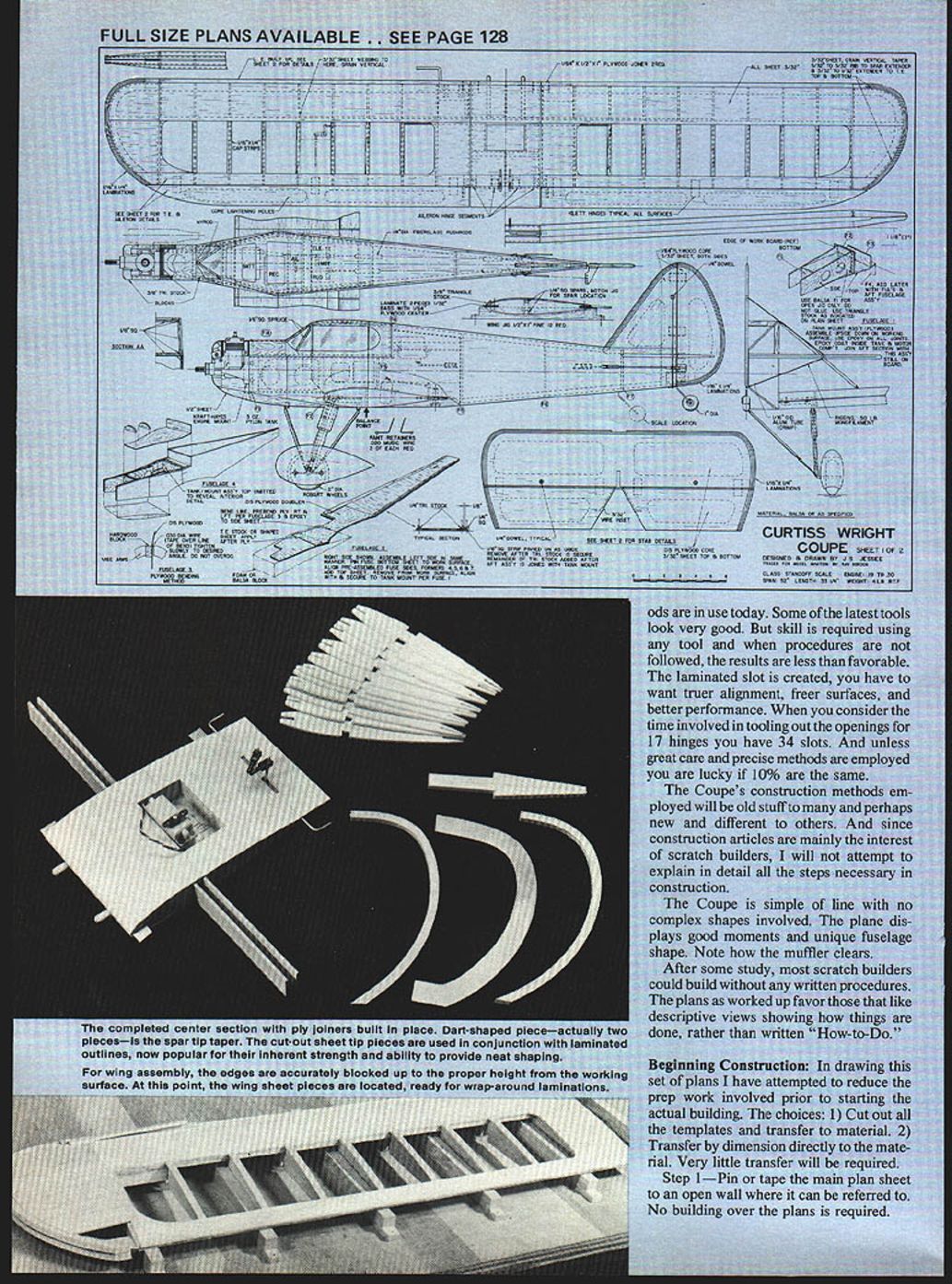
The Coupe is simple in line with no complex shapes involved. The plane displays good moments and a unique fuselage shape. Note how the muffler clears.
After some study, most scratch builders could build without any written procedures. The plans favor those who like descriptive views showing how things are done rather than long written "how‑to" instructions.
Beginning Construction
In drawing this set of plans I have attempted to reduce the prep work required prior to starting actual building. The choices are:
- Cut out all the templates and transfer to material.
- Transfer by dimension directly to the material.
Very little transfer will be required.
Step 1 — Pin or tape the main plan sheet to an open wall where it can be referred to. Do not build over the plans.
Step 2 — Cut out all parts and rubber‑band, pin, or tape them together in groups.
Step 3 — Work on a group at a time; work until a drying period is reached, then move to another group. Continue this cycle until all subassemblies are finished. This method reduces downtime and keeps parts drying between sessions.
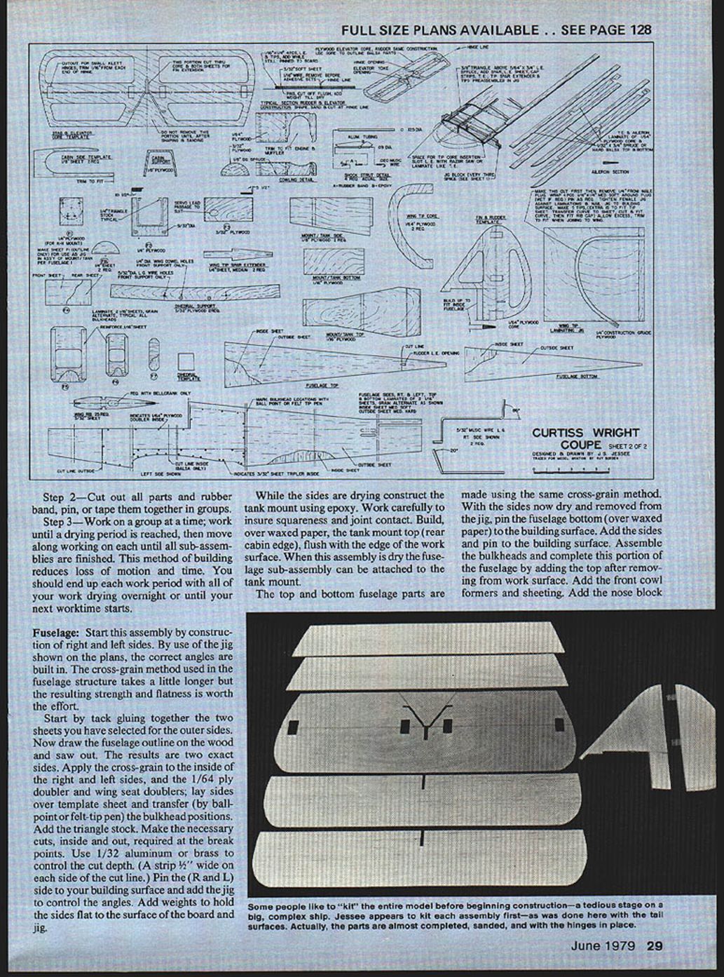
Fuselage
Start by constructing the right and left sides. Use the jig shown on the plans to build the correct angles. The cross‑grain method used in the fuselage structure takes a little longer but the resulting strength and flatness are worth the effort.
- Tack‑glue together the two sheets selected for the outer sides. Draw the fuselage outline on the glued sheet and saw out. This yields two exact sides.
- Apply the cross‑grain to the inside of the right and left sides, add the 1/64" ply doubler and wing seat doublers.
- Lay sides over the template sheet and transfer bulkhead positions (ballpoint or felt‑tip pen).
- Add triangle stock and make necessary inside and outside cuts at break points. Use 1/32" aluminum or brass to control cut depth (a 1/8" wide strip on each side of the cut line helps).
- Pin the right and left sides to your building surface and add the jig to control angles. Add weights to hold sides flat.
While the sides are drying:
- Construct the tank mount using epoxy; ensure squareness and joint contact.
- Build the tank mount top (rear cabin edge) over waxed paper, flush with the edge of the work surface. When dry, attach the fuselage subassembly to the tank mount.
Top and bottom fuselage parts are made using the same cross‑grain method:
- With the sides dry, pin the fuselage bottom over waxed paper to the building surface. Add the sides and pin.
- Assemble the bulkheads and complete this portion by adding the top after removing from the work surface.
- Add front cowl formers and sheeting, then add the nose block. Shape the nose block by rough saw‑cutting, then carve and sand‑blend.
- Saw‑cut the lower nose block (top and side profiles), add and blend into the fuselage.
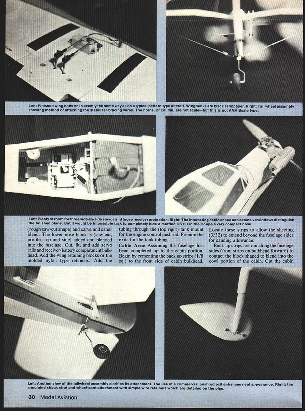
- Cut, fit, and add servo rails and the receiver/battery compartment bulkhead.
- Add wing‑retaining blocks or molded nylon retainers.
- Add the tubing through the top‑right tank mount for the engine control pushrod and prepare exits for tank tubing.
Cabin Area
Assuming the fuselage is complete to the cabin portion:
- Cement back‑up strips (1/8" sq.) to the front side of the cabin bulkhead. Locate these strips to allow the 3/32" sheeting to extend beyond the fuselage sides for sanding allowance.
- Run backup strips along the fuselage sides (from strips on bulkhead forward) to contact the block shaped to blend into the cowl.
- Cut and fit the cabin window area parts into the top side and rear backing strip support area. Sand to blend.
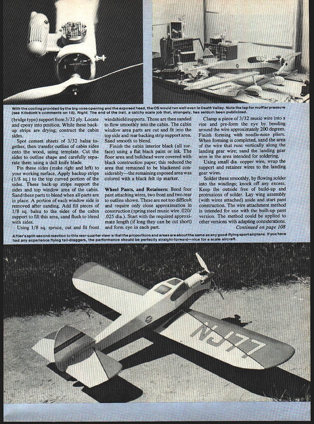
Finish the cabin interior flat black. The floor area and bulkhead can be covered with black construction paper to reduce the area needing paint; remaining exposed area can be colored with a black felt‑tip marker.
Wheel Pants and Retainers
- Bend four pant‑attaching wires — two front and two rear — to the outline shown on the plans. Use spring‑steel music wire .020–.025" dia.
- Form an eye in each part: clamp a piece of 3/32" music wire in a vise and pre‑form the eye by bending around the wire approximately 200 degrees, then finish with needle‑nose pliers.
- Sand the area of the wire that runs vertically along the landing gear wire and sand the landing gear wire where soldering will occur.
- Using small‑dia copper wire, wrap the support and retainer wires to the landing gear wires. Solder smoothly by flowing solder into the windings; remove any excess. Keep the outside free of build‑up and protrusions.
Pant construction (laminated balsa):
- Laminate balsa stock together using spot cementing; cut four outer pant parts and two inner core parts.
- Epoxy parts together with thin coats on contacting surfaces, pin to ensure alignment and clamp/weight until dry.
- From the template mark axle hole location on the dried, rough paint build‑up. Drill 1/4" dia. holes all the way through for the axle (a drill stand is helpful).
- Use nylon bushings in the pant axle holes (inside). Cement a balsa cap to the outside and sand smooth. The axle should seat into dowel‑drilled bushings; use plywood washers centered over the axle holes inside.
- With the fuselage and tail complete, attach the wing and set up a cleared work area.
- Slip on the tailwheel pants and main wheels. Use a wheel collar inside the pants to lock the axle temporarily. Use a block to jack up the rear portion of the pants off the work surface to the position shown on the plans or make a cardboard jig using the side profile (lower wing surface to top profile of pants).
- Move the pant support wires inward as close as possible to the inside surface and mark through the wire eye in four places to locate attachment screw holes.
- Remove the pants and, using a drill stand, make four 3/16" dia. holes approximately 3/8" deep.
- Transfer the top outline shape of the pant onto the rough pant. Saw out profiles, then carve, file and sand to finished shape.
- Prepare four pieces of 1/4" hardwood dowel about 1‑1/4" long; drill .040–.060" holes through each plug. Slip‑fit these plugs into the pants, mark the cutoff line, trim, and sand flush slightly below the pant surface. Prime and sand the finished pants.
- The hardwood plugs in the holes should be about 1/8"–3/16" below the surface. When the eye‑assembled screws are installed they will draw the pants inward and secure them in place.
- Assemble the pant by inserting the axle through the pant sidewall, add a shim washer (plastic if possible), the wheel, outer shim, and retaining wheel collar. Rotate the pants until holes line up and add retaining screws. Adjust spring wires for proper alignment and add shock struts for appearance and function.
Wing
The wing construction is straightforward except for the jig method and leading/trailing edge structure.
- Prepare ribs by the stack‑and‑saw method; if you lack a bandsaw, use the one‑at‑a‑time template method.
- Outline the wing tip curve parts from template (1/64" ply) and construct a wing tip curve jig (foam core is useful).
- The laminated ply sandwich tips take about an hour to assemble. Final shaping, sanding and blending are done when each panel's top surface structure is dry.
- Use jig blocks (2" x 4") pinned to the building surface and a T‑square to align them. Drive small nails through the short step notch into the board.
- Pin leading and trailing edges to the jig, slide ribs onto the leading edge at an angle, rotate to marked rib spacing, glue and pin.
- Add triangle stock on top, the spar out to the double rib location, and leading edge/trailing edge sheeting and cap strips.
- When dry, notch ribs to allow tip alignment extensions to be added. Re‑jig the wing with small glue blocks and pin for tip assembly. Glue right and left tip subassemblies (curve on top side first; bottom curves added later). When dry, slide top plywood extensions into the leading and trailing edge slots, check fit before final glue.
- Cut tip sheeting and support strips cross‑grain to bend easily; start at the leading edge with about 1/8" strips tapering to about 1/32".
- After top surfaces are finished, cut rib webbing to allow center section plywood gussets. Trim spars for proper dihedral angles and align root ribs. Add landing gear blocks, support ribs, drill for gear hold‑down straps; install gear and epoxy clamps.
- Finish wing by adding lower‑tips, spar webbing, lower sheeting and cap strips. Carve, plane, file, and sand‑blend to finish. Joining wing sections requires careful attention and step planning.
Tail Surfaces
The rudder/fin and stabilizer/elevator are sandwich structures of balsa and plywood core. Laminated outlines add stiffness and resist denting better than single‑grain structure. They are also easier to sand and shape, allowing soft balsa filler shapes.
- The lightened plywood core carries the hinge and fin extension slot to improve alignment and strength.
- Prepare assemblies so the outline profile can be sawed out after glue‑ups are finished, ensuring perimeter squareness.
- Use a 1/16" dia. music wire as a hinge gap spacer tool.
- Predrill 1/4" dowel holes for the tail brace; use these as alignment keys and draw center lines in ballpoint for alignment.
- Complete all sanding and laminating before shaping and sand‑blending. Use medium‑hard straight‑grained balsa for laminations (1/16" x 1/4").
- Wet pieces only where tight radius bends are required. Use soft 3/32" sheets on each side of the 1/64" plywood core for sanding allowance.
- Prior to hinging, separate the surfaces at the hinge line with a small saw or several knife passes. Sand and round edges where required. Add brace wire and 1/4" hardwood dowels; slip in and out while sanding until flush before final gluing. Predrill the 1/16" holes through the dowels before final assembly.
Finishing
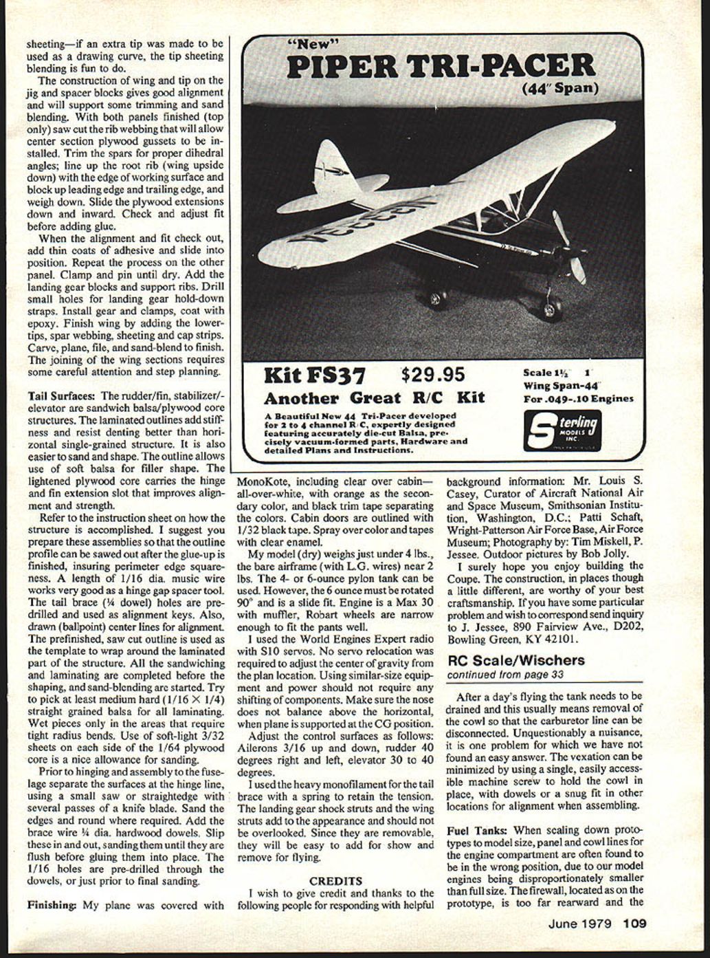
- Cover the model with MonoKote (I used all‑over white with orange as the secondary color and black trim tape separating colors). Outline cabin doors with 1/32" black tape. Spray over color and tapes with clear enamel.
- My model (dry) weighs just under 4 lbs.; the bare airframe with landing gear wires is near 2 lbs.
- Use a 4‑ or 6‑ounce pylon tank. The 6 oz. tank must be rotated 90° and fitted as a side tank for clearance.
- Engine used: Max 30 with muffler. Robart wheels are narrow enough to fit the pants well.
- Radio used: World Engines Expert with S10 servos. No servo relocation was required to adjust the CG from the plan location. Using similar sized equipment and power should not require shifting components.
- Make sure the nose does not balance above the horizontal when the plane is supported at the CG position.
Control surface recommended throws:
- Ailerons: 3/16" up and down
- Rudder: 40° right and left
- Elevator: 30° to 40°
I used heavy monofilament for the tail brace with a spring to retain tension. The landing gear shock struts and wing struts add to appearance and should not be overlooked. Since they are removable, they are easy to add for show and remove for flying.
CREDITS
I wish to give credit and thanks to the following people for responding with helpful background information:
- Mr. Louis S. Casey, Curator of Aircraft, National Air and Space Museum, Smithsonian Institution, Washington, D.C.
- Patti Schaft, Wright‑Patterson Air Force Base, Air Force Museum.
Photography by Tim Miskell and P. Jessee. Outdoor pictures by Bob Jolly.
I hope you enjoy building the Coupe. The construction, though in places a little different, is worthy of your best craftsmanship. If you have a particular problem and wish to correspond, send inquiries to: J. Jessee 890 Fairview Ave., D202 Bowling Green, KY 42101
Transcribed from original scans by AI. Minor OCR errors may remain.

