
Custom Mods
Fred Berman
If you're one of those people who can never just leave things alone, you can appreciate my approach to modeling. If you're not accustomed to modifying kits to better suit your needs, read on — the modifying bug might just bite you.
Why Modify?
When there's something you don't like about a device, kit, or design, why not modify it to conform to your individual needs? You have ideas, imagination, experience, and a personal interest unencumbered by commercial ties. All this more than qualifies you to make individualized revisions — "customized modifications," or "custom mods" for short.
There's a bit of maverick in all of us. Perfection is an ideal approached from various angles and seldom agreed upon. What's "perfect" often depends on special situations.
Landing-gear choices: tri-gear vs taildragger
Consider the controversy over landing-gear configuration — tri-gear or taildragger? At my club we have a single grass runway regularly blitzed by crosswinds. In that situation, taildraggers often take off with greater reliability than tri-gear types.
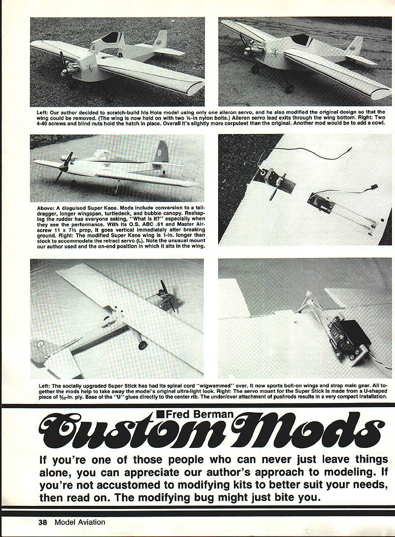
I'm familiar with proper full-size technique — having flown a Beech Bonanza for 1,000 hours — but techniques that work for a 1,500-lb airplane don't always translate well to models. A blustery hand launch can tip the upwind wing, dig a wheel, and send the prop into a sod-viscosity stall. If the kit has the "wrong" landing gear setup, the solution is simple: build it your way. Taildraggers also have the advantage of requiring one fewer retract mechanism and less servo clutter in the belly when retracts are planned.
Examples of Mods
Super Kaos / MK Aurora: taildragger conversion and turtledeck
A number of fliers have converted models like the Super Kaos and the MK Aurora to taildraggers. In an earlier phase of my RC apprenticeship, my Super Kaos suffered a misadventure partly due to a silhouette that was difficult to track (the conventional Kaos back looked much like its belly). To correct that, I turtledecked the next version and added a leftover canopy from a Sig Kavalier.
Since the plans didn't detail retract installation, I devised my own scheme: instead of leaving the center wing ribs as drawn, I cut the center ribs, mounted the retract servo there, added a couple of ply dihedral braces, and elongated the wing about 1 inch. Rather than butting the wing halves center-to-center, the panels now overlap the fuselage center and the retracts fold into the wing.
Minor anti-nuisance fixes
Oftentimes mods are just minor fixes:
- Replaced slotted-head screws on Dave Brown retracts and Goldberg pushrod connectors with socket-head screws (originals were 6-32; replacements 4-40) for easier driving.
- Reshaped a rudder and vertical stab with balsa and cyanoacrylate to create a unique "mystery ship."
Super Stik: rump shaping, torque rods, bolted wings
On another kit (a Stik), I wasn't happy with the rubber-banded wings, bellcranked ailerons, or the flat rump. My mods included:
- Replacing bellcranks with direct-coupled aileron torque rods using 1/8-in. Goldberg aileron horns.
- Gluing a ply servo frame directly on the fuselage instead of cutting the center rib; added a small "back porch" to get torque elbows inside.
- Tenting the rump with tapered MonoKote supported by a minimal triangular-balsa frame.
- Converting rubberbanded wings to bolted-on: glued 1/4-20 threaded maple blocks to the fuselage sides to lock the wing trailing edge and used contoured maple cheeks to engage the dowel intended for the forward rubberband.
The result: a shapelier, more reliable Super Stik with accessible pushrods and secure wing attachment.
Aeromaster Two: disaster recovery and fixed wings
My Aeromaster Two had a spectacular failure: during a shakedown the engine and mount departed the engine compartment, leaving the plane to spiral into a 70-ft tree. After two days in the tree (and a storm that later dislodged the plane), I recovered it — arrows stuck in the wing but largely intact. The Aeromaster went to my mod shop and emerged with fixed wings and fixed gear.
Wing bolt-on method I used:
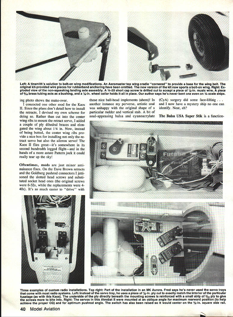
- Eliminated top-wing rubberband cradles; substituted triangular 1/16-in. plywood pieces tapered to fit slots in the top of the fuselage sides.
- Upper wing attachment used tapped maple "nuts" in slats and short nylon bolts; lower wing used a pair of dowels up front and two tapped maple blocks in the rear.
- Lower wing also attached with a pair of 4-40 screws and blind nuts; aileron servo lead exits through the wing bottom.
Landing gear changes:
- Replaced kit wire gear with a Halco gear bolted into 6-32 blind nuts.
- Modified Halco wheel hubs by removing crimped locking nuts, center-drilling short 1/4-in cap screws, soldering 1/8-in music-wire axles to the screw heads, slipping 3/32-in K&S brass tubing over the axles, and securing with a 1/8-in wheel collar.
Great Planes later discontinued rubber-band wing retention on that model, independently corroborating my bias against rubberbands.
Installing Retracts
Most plans don't give a clear retract layout. My approach:
- Modify center wing ribs to create space for retract servos.
- Add ply dihedral braces and lengthen the wing about 1 inch so panels overlap at the center instead of butting.
- Route retracts to fold into the wing where possible to simplify the fuselage belly.
Servo Mounting and Switch Operation
Radio manufacturers provide plastic servo trays, but I prefer a custom approach:
- Mount servos on a 1/8-in. plywood platform tailored to the model's fuselage cavity to optimize placement and CG influence.
- Cut servo case openings large enough to avoid vibration transfer; drill 1/16-in. pilot holes for hold-down screws.
- Glue 1/16-in. "L" or "U" ply strips under screw locations for added bite.
- Place the battery on the servo platform in an appropriate spot.
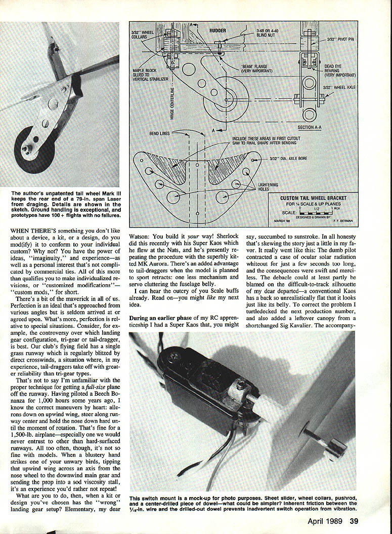
External switch operation: a simple, reliable slider arrangement can be made from:
Materials:
- Small piece of thin metal sheet (copper, brass, or steel)
- Two 1/16-in. wheel collars
- Short length of 1/32-in. music wire
- Short piece of 1/16- or 1/8-in. hardwood dowel
Method (summary):
- Make a frame from the flattened metal sheet to carry the switch slider; solder one wheel collar to the frame.
- Drill a hole in the fuselage skin aligned with the collar center; install the dowel with a 1/16-in. hole drilled through it.
- Attach the second wheel collar to a length of music wire, push it through the dowel from outside, and lock it onto the collar on the slider frame.
This arrangement uses friction and positive retention so it won't slip.
Filling, Repairs, and Small Tricks
- Filling large dents/gaps: keep a bag of balsa dust. Fill the void with balsa dust (wetted for better adhesion), then add one or more drops of thin cyanoacrylate. After curing, sand and finish.
- Frequency flags and other shop gizmos: small parts like miniature coil springs and music wire lengths are useful for improvised solutions around the shop.
Flaperons
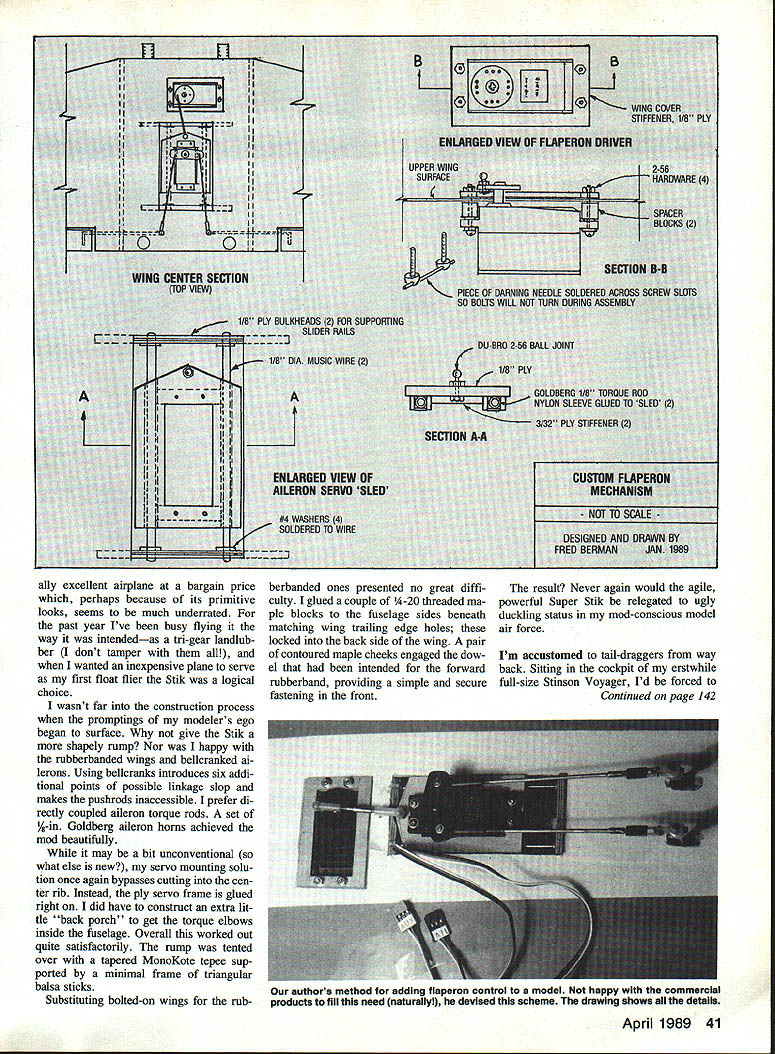
Flaperons are my alternative to building complex flaps and linkages. I evaluated a cheap commercial V-tail mixer but designed my own for two reasons:
- I disliked asymmetrical aileron deflection in the "flaps" mode.
- I didn't trust set-screw friction on a 3/32-in shaft for a secure drive under aerodynamic loads.
My arrangement saddles the entire aileron servo onto a sled driven by the flap servo. The completed flaperons perform well and retain full aileron servo integrity.
Notes:
- I operate flaperons fully on/off with a retract channel on my five-channel radio; stepped operation requires six or more channels.
- Caution: most wings show diminished aileron response when flaps are deployed and will require heavier stick input.
Closing
Doing things better — that is, your way — comes in all sizes, shapes, and forms. Just about anything is fair game for the modeler who can imagine how something might be improved. If you enjoy tinkering, the satisfaction of a thoughtful custom mod can be far greater than simply accepting the kit as-is.
Transcribed from original scans by AI. Minor OCR errors may remain.

