
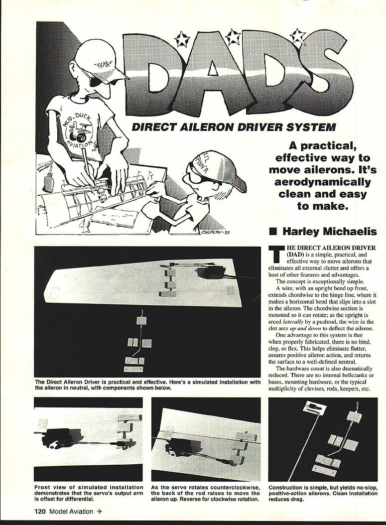
Dads: Direct Aileron Driver System
A practical, effective way to move ailerons. It's aerodynamically clean and easy to make.
Harley Michaelis
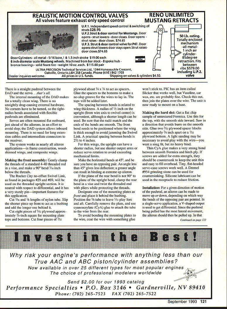
The Direct Aileron Driver (DAD) is a simple, practical, and effective way to move ailerons that eliminates all external clutter and offers a host of other features and advantages.
The concept is exceptionally simple. A wire, with an upright bend up front, extends chordwise to the hinge line, where it makes a horizontal bend that slips into a slot in the aileron. The chordwise section is mounted so it can rotate; as the upright is arced laterally by a pushrod, the wire in the slot arcs up and down to deflect the aileron.
One advantage to this system is that when properly fabricated there is no bind, slop, or flex. This helps eliminate flutter, assures positive aileron action, and returns the surface to a well-defined neutral.
The hardware count is also dramatically reduced. There are no internal bellcranks or bases, mounting hardware, or the typical multiplicity of clevises, rods, keepers, etc. There is a straight pushrod between the DAD and the servo — that's all.
The internal mounting of the DAD makes for a totally clean wing. There is no unsightly drag-causing external hardware. No corners have to be turned, so the tight-radius bends associated with flexible pushrods are eliminated.
Servos are often mounted flat outboard, just ahead of the ailerons, in an effort to avoid slop; the DAD system allows inboard mounting. There is no need for long extension cables and intermediate connectors to the receiver.
The system works in nearly all aileron applications — framed construction, wood-skinned wings, and composite wings.
Advantages
- Eliminates external clutter and drag-causing hardware.
- Reduces number of parts (no internal bellcranks, multiple clevises, etc.).
- Minimal slop, bind, or flex when properly made — reduces flutter and gives positive action.
- Allows inboard servo mounting; avoids long extension runs.
- Works with framed, wood-skinned, and composite wings.
Making the front assembly
- Materials and initial bend
- Use a standard 4-40 threaded rod. Gently clamp the threads in a vise and make a 90° bend 3/16 inch below the threads.
- The Rocket City no-offset Swivel Link (as found in packages #29 and #69) is used on the threaded upright section. It is neutral with respect to differential and has a very sturdy pin — important features for this application.
- Bushings and mounting plates
- Cut 3/16" and 3/8" lengths of nylon tube. Slip the shorter piece up front to act as a bushing and add the longer one behind it.
- Cut eight pieces of 1/32" plywood approximately 3-1/4 inches square for mounting plate tops and bottoms.
- Cut four pieces of 1/32" plywood to act as spacers. Glue spacers to the bottoms to make a no-slop groove for the wires to lay in. The tops will be added later.
- Bend spacing and radii
- The spacing between bends is related to wing thickness. A radius of 1/2 inch on the upright (from wire axis to swivel center) is convenient, although a shorter radius can be used for thin wings.
- Be sure the radii match and the ends of the bends are smooth.
- The front bend needs to be positioned where the wing is thick enough to avoid jamming the Swivel Link. A practical spacing between bends is 2-1/2 to 4 inches.
- For thin wings, use a shorter upright radius, but use shorter output arms or reduce servo rotation to avoid exceeding mechanical limits.
- Output bend angles
- Make the horizontal bends at 45° and be sure you have an opposing pair.
- An angle less than 45° gives less deflection; a greater angle can result in binding at extreme up aileron.
- If the plane of the rear bend is not 90° to the plane of the upright bend, clamp the rear bend in a vise and twist the threaded end with pliers while protecting the threads.
- Assembly
- Designate one of the mounting plates as front and place it behind the bushing. Position the 3/8" tube to leave 1/32" play fore and aft.
- Carefully remove the plate and use cyanoacrylate (CyA) glue to attach the tube to the wire from the rear.
- To avoid bonding the mounting plates to the wire, coat the wire with something glue won't stick to (PIC sells a product called "Slicker"; alternatives include Vaseline or car wax). Check this out, then join the plates over the wire.
- The unit is now ready to mount on a base.
Making the hard slot
- Get a flat chip sample of uncoated Formica. Use the smooth side inward for the top.
- Saw in a direction that avoids burrs on the smooth side.
- Glue two 3/32" plywood spacer blocks approximately 3/8" apart on a 1/32" plywood bottom.
- Lightly sand as necessary to avoid play with the wire — you want a snug fit, but no heavy bind.
- Thin CyA glue makes a very strong bond between smooth Formica and ply.
- If screws are added for extra strength, countersink them to keep the unit thin and easy to fill over. Tiny, flat-headed servo-case screws work well; a Dremel #54 grinding stone can be used for countersinking.
- Silicone lubricant can be applied in the receptacle to reduce friction.
Installation
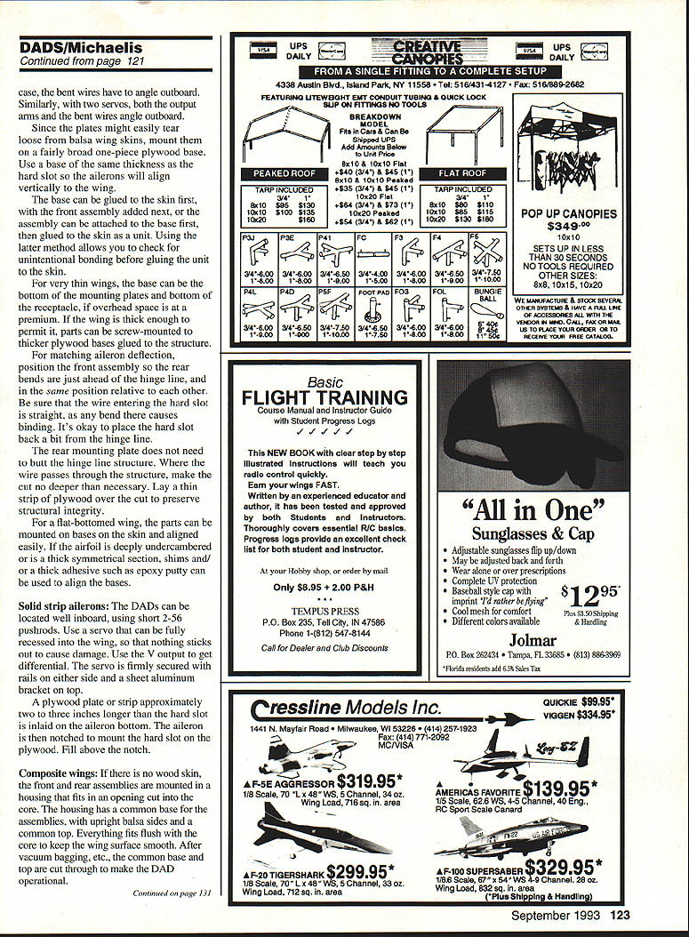
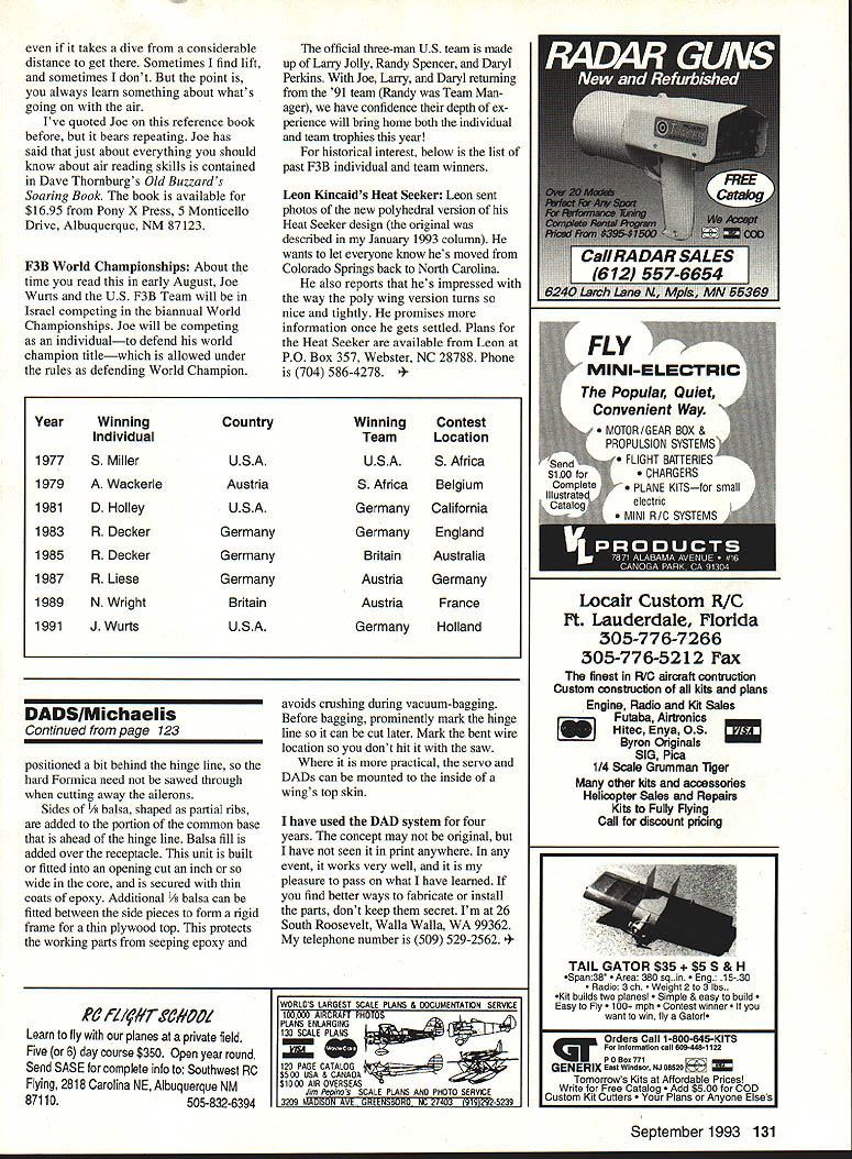
- For a given direction of motion of the pushrod, an aileron can be made to move up or down depending on which way the bends of the opposing pair are pointed.
- In a single-servo application, a V-shaped output is used to get differential. Since the pushrod being pulled has the most lateral movement, the aileron should then be pulled up; in that case the bent wires have to angle outboard. Similarly, with two servos, both the output arms and the bent wires angle outboard.
- Since the plates might easily tear loose from balsa wing skins, mount them on a fairly broad one-piece plywood base. Use a base of the same thickness as the hard slot so the ailerons will align vertically with the wing.
- Two mounting methods:
- Glue the base to the skin first, then add the front assembly.
- Attach the assembly to the base first, then glue the unit to the skin. The latter allows you to check for unintentional bonding before final assembly.
- For very thin wings, the base can be the bottom of the mounting plates and bottom of the receptacle if overhead space is at a premium.
- If the wing is thick enough, parts can be screw-mounted to thicker plywood bases glued to the structure.
- For matching aileron deflection, position the front assembly so the rear bends are just ahead of the hinge line, and in the same position relative to each other. Be sure the wire entering the hard slot is straight, as any bend there causes binding. It's okay to place the hard slot back a bit from the hinge line.
- The rear mounting plate does not need to butt the hinge-line structure. Where the wire passes through the structure, make the cut no deeper than necessary; lay a thin strip of plywood over the cut to preserve structural integrity.
- For a flat-bottomed wing, parts can be mounted on bases on the skin and aligned easily. If the airfoil is deeply undercambered or is a thick symmetrical section, shims and/or a thick adhesive such as epoxy putty can be used to align the bases.
Solid strip ailerons
- The DADs can be located well inboard using short 2-56 pushrods.
- Use a servo that can be fully recessed into the wing so that nothing sticks out to cause damage.
- Use the V output to get differential.
- Secure the servo firmly with rails on either side and a sheet-aluminum bracket on top.
- A plywood plate or strip approximately two to three inches longer than the hard slot is inlaid on the aileron bottom. The aileron is then notched to mount the hard slot on the plywood; fill above the notch.
Composite wings
- If there is no wood skin, mount the front and rear assemblies in a housing that fits in an opening cut into the core.
- The housing should have a common base for the assemblies, with upright balsa sides and a common top. Everything fits flush with the core to keep the wing surface smooth.
- After vacuum-bagging and curing, cut the common base and top to make the DAD operational. Position slightly behind the hinge line so the hard Formica need not be sawed through when cutting away the ailerons.
- Add sides of 1/4" balsa, shaped as partial ribs, to the portion of the common base that is ahead of the hinge line. Add balsa fill over the receptacle.
- Build or fit this unit into an opening cut an inch or so wide in the core and secure with thin coats of epoxy. Additional 1/8" balsa can be fitted between the side pieces to form a rigid frame for a thin plywood top; this protects the working parts from seeping epoxy and avoids crushing during vacuum-bagging.
- Before bagging, prominently mark the hinge line so it can be cut later. Mark the bent wire location so you don't hit it with the saw.
- Where more practical, the servo and DADs can be mounted to the inside of a wing's top skin.
Experience and contact
I have used the DAD system for four years. The concept may not be original, but I have not seen it in print anywhere. In any event, it works very well, and I am pleased to pass on what I have learned. If you find better ways to fabricate or install the parts, don't keep them secret.
Address: 26 South Roosevelt, Walla Walla, WA 99362 Telephone: (509) 529-2562
Transcribed from original scans by AI. Minor OCR errors may remain.

