
DAVIS D1K
A. A. Lidberg
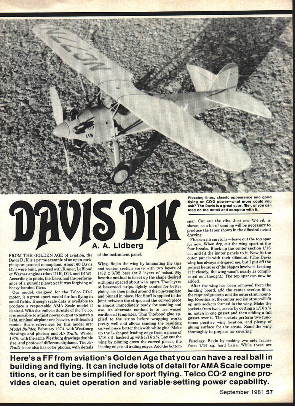
From the golden age of aviation, the Davis D1K is a prime example of an open-cockpit sport parasol monoplane. About 60 Davis D1s were built, powered with Kinner, LeBlond or Warner engines (thus D1K, D1L and D1W). Pilots say the Davis had the performance of a pursuit plane, yet was forgiving of heavy-handed fliers.
Our model, designed for the Telco CO-2 motor, is an excellent sport model for fun flying in small fields. Enough scale data exists to produce a respectable AMA Scale model if desired. With the Telco's built-in throttle you can tune power for a light, minimal airplane or a heavier, detailed model.
Scale references:
- Model Builder, February 1974 (Westburg drawings and photos).
- Air Trails, Winter 1976 (Westburg drawings doubled in size; photos of different airplanes and color photos with instrument-panel detail).
Wing
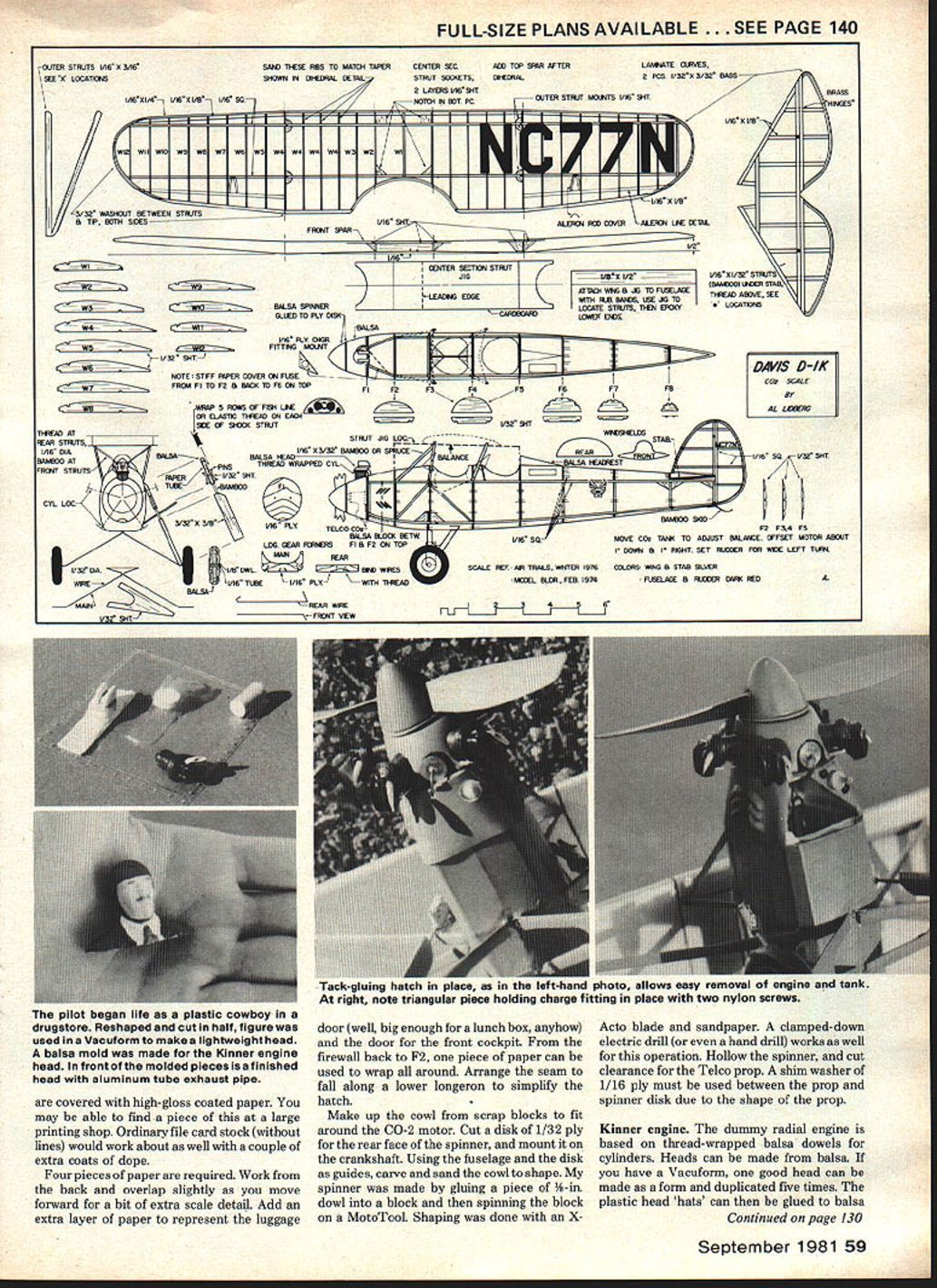
- Begin by laminating the tips and center-section curve with two layers of 1/32 x 3/32 bass (or three layers of balsa). Pin a template spaced about 1/4 in. apart and pull the strips around the pins.
- Glue options: Hot Stuff applied at the joint sets quickly for early sanding; Thin Titebond applied before wrapping sands better than white glue. Waxed cardboard templates are an alternate method.
- Make the L-shaped leading edge from 1/16 x 1/16 backed up with another 1/16 x 1/16. Lay out the wing, pinning curved pieces, the leading and trailing edges, and add the bottom spar.
- Cut out ribs; fit each rib carefully, leaving out the top spar for now. Only one W4 rib is shown on the plan, so sand to produce the taper shown in the dihedral detail drawing.
- When dry, cut the wing apart at the four breaks. Block up the center section 1/16 in. and fit the inner panels to it. Fit the outer panels with dihedral, then add the top spar.
- After removing the wing from the board, add the center-section filler, required gussets, and the outer strut mounting. The center-section struts will fit into sockets formed in the wing—make these sockets from two gussets by cutting a 1/16 x 3/8 in. notch in one gusset and adding a full gusset over it. The sockets give positive wing location and plenty of glue surface.
- Sand the wing thoroughly to prepare for covering.
Fuselage
- Make two side frames from 1/16 sq. hard balsa. While drying, cut out formers, plywood firewall, charger fitting, mount and landing gear formers.
- Pin sides upside down over the top view and put cross braces between F2–F5. Crack sides at F2; the forward part can be bent to firewall width. Clamp and glue tailposts together and fill remaining cross braces.
- Bend main landing gear from 1/32 wire; bind to the main gear former with heavy thread. Bend and bind rear struts and rear gear former.
- Glue the main gear former in place ahead of the upright; fit and glue the rear gear former. Wrap the joint between rear main gear wires with fine copper wire and solder to keep them joined.
- Add gussets to brace landing gear formers. Make balsa filler pieces for the landing gear wires and epoxy them in place.
- When dry, remove the fuselage from the board and add remaining formers and stringers.
Firewall and CO-2 Motor
- Temporarily fit the Telco CO-2 motor/tank unit. Bend tubing so the tank lies under the balance point. Provide solid mounting and charger fitting.
- Tap 2-56 threads in the fitting holes. A right-size steel 2-56 screw can be used as a tap by filing a triangular-shaped groove over about six threads. The fitting can be held with model 2-56 nylon screws.
- Because charging requires significant force (about 4 lb), strengthen the nose section: fill between the firewall and former F2 with a soft balsa block hollowed for lightness. Make a similar hollowed block between the firewall and the main landing-gear former. Tack-glue these in place; they can be cut later to form the hatch.
- When fitting the tank, ensure the outlet is elevated—if the tank is at or below horizontal, liquid CO-2 may freeze the line to the motor and shut it off.
Body Covering and Paper Detail
- After sanding, cover the body with tissue. Note the upper and front portions will later be covered with stiff, high-gloss coated paper (file card stock without lines can substitute with extra coats of dope).
- Work with four pieces of paper: start from the back and overlap slightly as you move forward for scale detail. Add an extra layer of paper for the luggage door and the door for the front cockpit.
- From the firewall back to F2 a single piece of paper can wrap all around; arrange the seam along a lower longeron to simplify the hatch.
- Shrink the tissue and give it a coat of very thin nitrate dope. The top and front portions received two coats on the author's model; the remainder received one coat.
Cowl and Spinner
- Make the cowl from scrap blocks to fit around the CO-2 motor. Cut a disk of 1/32 in. ply for the rear face of the spinner and mount it on the crankshaft.
- Using the fuselage and disk as guides, carve and sand the cowl to shape. The spinner was made by gluing a piece of 1/16-in. dowel into a block and spinning it on a MotoTool; shape with an X-Acto blade and sandpaper. A clamped electric drill or hand drill will work.
- Hollow the spinner and cut clearance for the Telco prop. Use a 1/16-in. plywood shim washer between the prop and spinner disk as needed.
Kinner Engine (Dummy)
- Build dummy radial cylinders from thread-wrapped balsa dowels. Make heads from balsa or form one head in a Vacuform and duplicate five times; glue plastic head 'hats' to balsa circles glued to the cylinders.
- Paint cylinder and head assemblies black before adding other details.
- Add exhaust and intake pipes from 1/16-in. aluminum tube and small strips of bamboo for pushrods. For spark plugs, glue thread to 1/4-in. lengths of a straight pin to simulate plugs and wires.
- Drill cowl holes for each cylinder, but leave cylinders and cowl holes off until after painting the model.
Wheels
- Turn wheels on the MotoTool. Epoxy a 1-in. length of 1/8-in. dowel to three laminations of balsa. Shape the wheels, then while revolving in the MotoTool start a center hole with a 1/32-in. drill and enlarge to 1/16-in. dia. for aluminum tube bearings.
- Paint tires flat black after sanding and filling.
Center-Section and Outer Struts
- Assemble struts from bamboo (preferred) or spruce. Make a cardboard strut jig to align struts squarely and attach it to the fuselage with rubber bands.
- Attach the wing with rubber bands above the jig. Upper ends of struts fit into sockets in the wing; the lower ends rest on the lower longerons.
- Carefully cut through the stiff paper to expose the longerons for each strut and trim struts to fit. When satisfied, epoxy the lower ends of the struts to the fuselage.
- Make up the outer struts, paint them red, and epoxy them in place after checking wing-panel straightness between center and outer struts. Once all struts are in place, remove the wing and jig for painting.
Tail Surfaces
- Moveable elevators and rudder were chosen for maximum scale points and in-flight adjustment.
- Laminate the curved outlines and use medium-hard balsa for the rest of the structure. After removing surfaces from the board, separate them along hinge lines and make hinge slots with a thin razor saw.
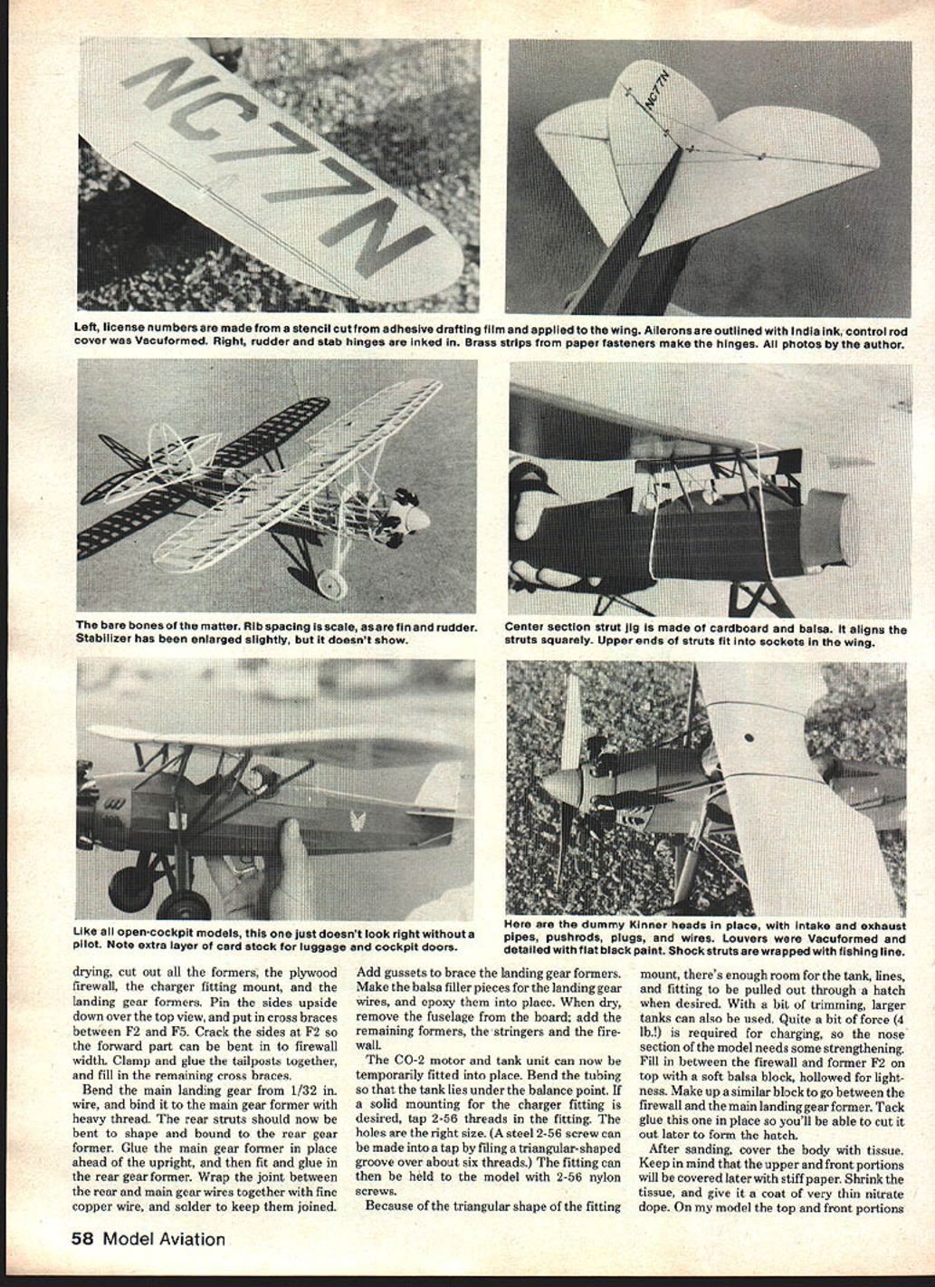
- Use brass strips from paper fasteners for hinges—insert the metal strips and leave a little space at the hinge line for bending. Hot Stuff holds the metal nicely.
- Steam any warps out of the tail surfaces, and steam in 3/32-in. washout into the outer wing panels outboard of the struts. Trailing edge at the tip should be 3/32 in. higher than the leading edge.
Surface Covering
- To minimize warps during tissue shrinking, spray rubbing alcohol through an old hair-spray pump bottle; alcohol dries faster and shrinks less tightly than water.
- Cover wing and tail with thin Japanese tissue. After shrinking, apply one or two coats of well-thinned plasticized nitrate dope (10 drops castor oil per ounce of uncut nitrate, then thin as needed).
Paint and Trim
- Recommended scheme for NC77N: silver wings and stabilizer, dark red fuselage and rudder (author painted the rudder silver by mistake and liked it).
- Floquil model railroad paints (bright silver, caboose red) were mixed with nitrate dope for a glossier finish. Suggested mixing approach:
- Let paint bottles settle, pour off clear liquid and discard.
- Fill bottles with nitrate thinner and shake.
- Mix this Floquil/thinner mix with clear plasticized nitrate dope and spray.
- A workable ratio is 5 parts Floquil/thinner mix to 3 parts thinned plasticized nitrate clear.
- Mask NC numbers from clear adhesive film (Zipatone or similar). After masking, lightly brush clear dope around each character to minimize color bleeding, then apply two thin coats of red.
- NC numbers on the rudder can be stick-on white letters or silver ink in a Leroy pen. Xerox two copies of the Davis sheet from the plan and rubber-cement them in place for alignment.
- Paint the Telco prop flat black on the rear face and wood color on the front using enamel. If not doing colored dope, gray and red tissue can create a lighter, quicker model.
Details and Cockpit
- After gluing the stabilizer in place (don't forget the triangular incidence block), add thin bamboo struts to the underside and thread rigging between fin and stabilizer on top. Add small balsa filler pieces next to the fin.
- Bend the bamboo tailskid by heating and glue it on.
- Cut out the instrument panel, glue it to an extra former and add it to the rear cockpit. Split #20 electrical insulation and slip it over cockpit edges for padded coamings.
- A pilot greatly improves scale appearance. The author modified a plastic cowboy figure and used a Vacuform to produce a lightweight pilot. Other options: carve balsa or styrofoam.
- Louvers were Vacuformed and detailed with flat black paint. Shock struts were wrapped with fishing line. Note extra layer of card stock for luggage and cockpit doors.
Flying
- For first flights leave off the spinner and dummy radial engine to save nerves and allow easier throttle adjustments. Tack-glue these parts later once trim is satisfactory.
- Balance point: 1-1/16 in. back from the center-section leading edge. Adjust tank location to achieve this balance; ensure the tank outlet is elevated.
- For glide tests, find a soft landing area. Steam in washout and set trailing edge tips higher than leading edges for a flat, fast glide with a wide (40–50 ft.) left circle if needed.
- Initial thrust-line trim: start with two layers of card stock behind one corner of the Telco case to aim thrust about 1° down and 1° right.
- Set the Telco throttle for about 60 seconds on a standard tank for first runs; this gives safer, limited power. Open the throttle slowly in stages to obtain a shallow climb.
- Charging nozzle orientation: hold the charger with the nozzle up for shorter runs during tests; point down for longer runs when satisfied.
- With a larger tank (6 cc vs. standard 2–3/4 cc) the Davis can fly with power on all the time, landing with the prop turning. Flights with a 6 cc tank can last about 1–1/2 minutes, reaching 75–100 ft. in leisurely turns.
- Protect the tank during landings with foam rubber around it to prevent damage to the structure.
Final notes:
- The Davis is a very enjoyable model to fly. All early flying took place in a grass-covered schoolyard. Eventually club flying and contest flying can be attempted.
- If you haven't tried CO-2 flying yet, note the author's clubmate's remark: "Anything that is that much fun ought to be illegal!"
Transcribed from original scans by AI. Minor OCR errors may remain.

