
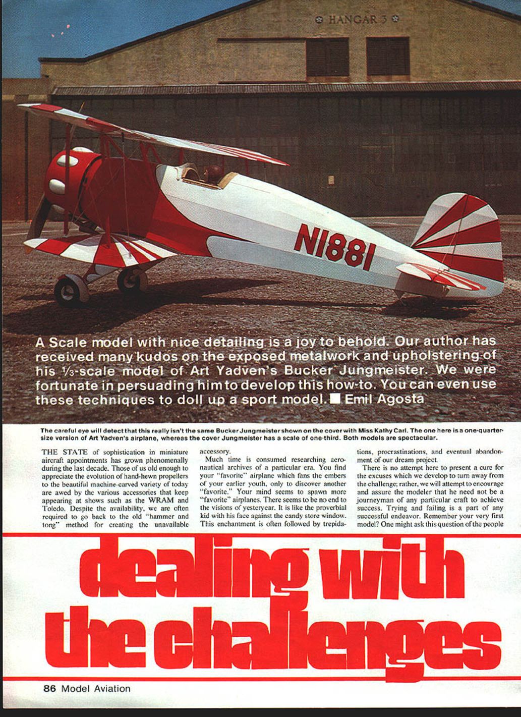
Dealing with the Challenges
The state of sophistication in miniature aircraft equipment has grown phenomenally during the last decade. Those of us old enough to appreciate the evolution from hand-hewn propellers to the beautiful machine-carved variety of today are awed by the various accessories that keep appearing at shows such as the WRAM and Toledo. Despite the availability of many items, we are often required to go back to the old "hammer-and-tong" method for creating an unavailable accessory.
Much time is consumed researching aeronautical archives of a particular era. You find your "favorite" airplane which fans the embers of your earlier youth, only to discover another "favorite." Your mind seems to spawn more "favorite" airplanes. There seems to be no end to the visions of yesteryear. It is like the proverbial kid with his face pressed against the candy-store window. This enchantment is often followed by trepidation, procrastination, and eventual abandonment of our dream project.
There is no attempt here to present a cure for the excuses we develop to turn away from the challenge; rather, we will attempt to encourage and assure the modeler that he need not be a journeyman of any particular craft to achieve success. Trying and failing is part of any successful endeavor. Remember your very first model? One might ask the same question of the people who first developed a retract system or an "over-balanced" flywheel!
Having built a quarter-scale model of Art Yadven's Bücker Jungmeister, I envisioned the possibility of a functional chrome- or nickel-plated exhaust stack on the one-third-scale version—just like the one on Yadven's big bird. The challenge was there. Tooling would have to be simple and applicable to other miniature aircraft. The two items on the Bücker that attracted the greatest interest at the 1981 WRAM Show were the metalwork on the exhaust stack and the realistic-looking upholstery work. Hopefully, some of the procedures outlined here will be of assistance in planning your "favorite" bird.
Mufflers and pipes
Some Quadra twin-pipe mufflers available today have large expansion chambers, and back-pressure is no problem. Too much pipe may prevent your engine from peaking out, and you may have to relegate your scale stack to its cosmetic value. Constant-diameter stacks should present no construction problems. However, if the header is visible and is conical or elliptical in shape, transitioning to a round stack—therein lies the rub.
Press dies
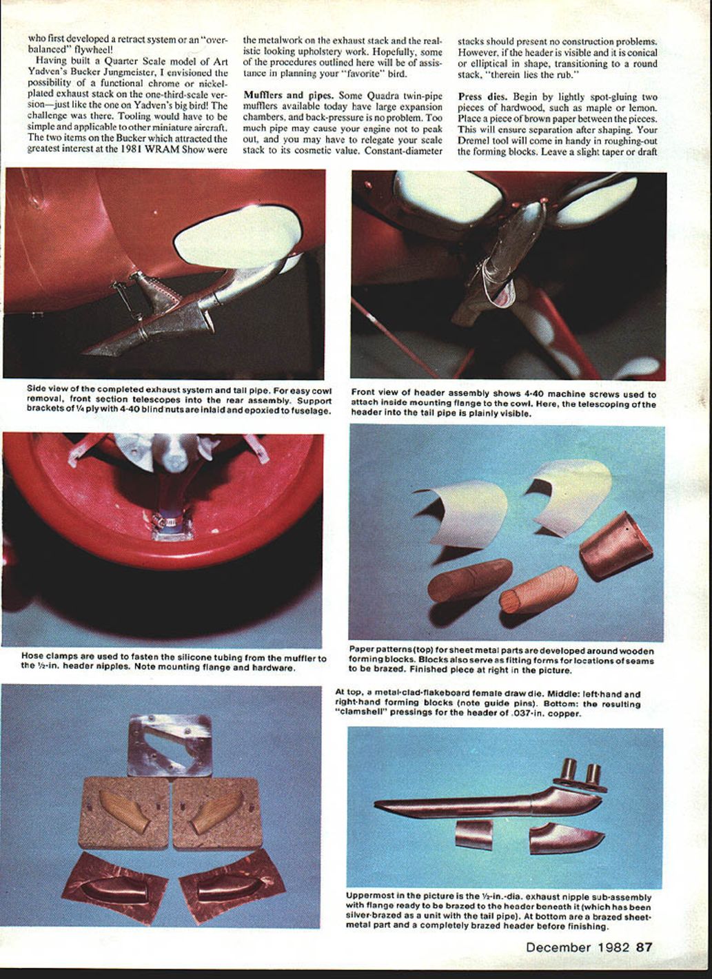
Begin by lightly spot-gluing two pieces of hardwood, such as maple or lemonwood. Place a piece of brown paper between the pieces so they will separate after shaping. Your Dremel tool will come in handy for roughing out the forming blocks. Leave a slight taper or draft on the blocks and mark whether they are left- or right-hand.
Next, cut out four pieces of 1/4-in. flakeboard. One piece will serve as the female draw die; two will serve as the male forming blocks over which the metal is stretched; the fourth piece will be used as a pressure plate placed over the drawing die. Flakeboard is manufactured under tons of hydraulic pressure, so have no fear. Trace the outline of the forming block and center it on the flakeboard. Jig out the opening 1/16 in. larger than necessary to provide clearance between the metal form and the press dies. File the opening free of saw marks.
Trace the outline of the opening onto 18-gauge sheet steel or 16-gauge dural and cut out a little shy, leaving material for final filing. Use a cheap manual nibbler to remove the bulk of the metal. Shape and refine the plates by progressively sanding to a smooth finish. Epoxy both metal plates to the draw-die flakeboard and align the openings. Weight everything down to cure overnight. After curing, dress and sand the opening to its final size. Further secure the metal plates with a few #4 or #6 by 3/8-in. flat-head screws. Drill the 3/16-in. guide-pin holes.
Using the drawing die as a drill jig, spot the guide-pin locations on two flakeboards. These holes must be drilled on a drill press for proper alignment. Use a drill a few thousandths undersize to press-fit the guide pins into the male dies. They should not extend more than 9/16 in. beyond the surfaces.
Be sure that the draw die slides over each male forming die by turning it over. Remember, the draw die will form both left- and right-hand pieces. If too tight, open holes up slightly with wire-gauge drills starting with a No. 10. With the draw die in place, trace through onto the flakeboard and epoxy the forming blocks within the outlines. Carefully center the blocks and check clearances. Again, check for left- and right-hand pressing.
The 20-gauge (.037-in.) copper blank size is not critical, but the less metal to press at the tail-pipe opening, the easier the job. The objective is to press a left and right "clamshell." The best downward pressure is obtained with a hydraulic arbor press. It will take only a few minutes to press pieces beyond your needs at your friendly automotive shop. If you are the improvising type, you can probably do wonders with a small hydraulic jack—try the concrete floor of your garage and the rear axle of your automobile.
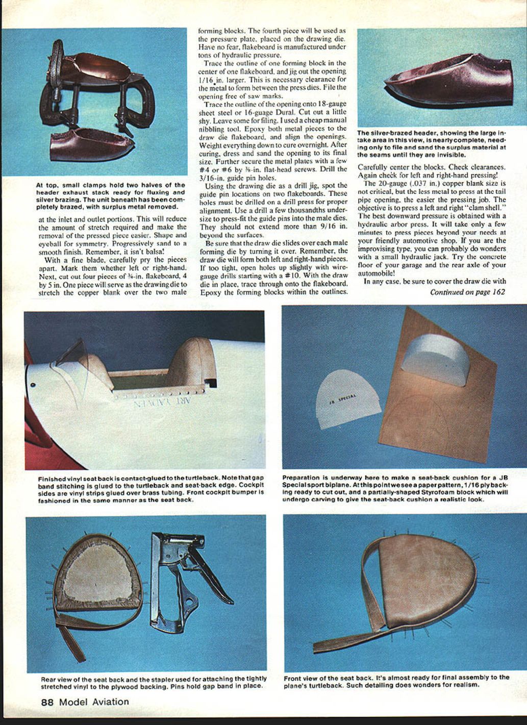
Be sure to cover the draw die with the remaining flakeboard pressure plate before pressing. As pressure is applied, the copper will stretch around the male forming block. Stop when you notice no more movement. After separating the dies, you will notice a fairly defined radius; however, there will be some wrinkles in the surplus metal. Gently hammer out the wrinkles on a steel plate or block. The "clamshells" should be matched up and perfectly mated. If necessary, lightly sand them on a flat surface. Trim the excess metal to within 1/8 in. of the radius and cut away openings. Don't worry about distortions at this point. Clamp for final assembly.
Silver brazing
Apply some Handy Flux to the inside seam. The silver solder will puddle between the two pieces, and when trimmed it will produce a fine, sturdy seam. Coat a small section of the brazing wire with flux. As heat is applied to the seam, the flux will begin to melt. When the proper temperature is reached, the solder will follow along the path of the flux and puddle into the seam.
A couple of salient points: the silver solder used in this process should not be confused with the extremely low-melting "silver solder" sold in hardware stores and hobby shops. The melting temperature of the silver solder for our purpose is near 1,100°F. It is available from refrigeration supply and craft supply houses.
At this point, the header mounting plate must be cut out. Drill two holes for 1/16-in.-diameter tubes about 1-1/2 in. long. Drill the mounting holes for 4-40 machine screws. Leave enough edge distance for elastic stop nuts. This subassembly is brazed to the header and mounted on the cowl with the finished tail pipe. Make the appropriate mounting brackets for your particular airplane.
Heat source
A Prestolite acetylene outfit is the best source of heat and will produce excellent penetration of the silver brazes. A couple of asbestos shingles will prevent your bench from being scorched. Also, a few fire bricks will be needed to rest the brazing work on. Safety glasses and a fire extinguisher are a must.
Finishing
After brazing is complete, all flux must be washed off with hot water. Some will have to be scraped off. Trim and file off all excess metal until the header looks and feels like a single piece. An electric sander is handy, but be sure to have a can of cold water nearby—the copper header will get mighty hot. The header openings can be touched up over some round steel stock clamped in a vise.
Tail pipe
Many airplanes have a single tail pipe located alongside the fuselage. Some in-line engines have this arrangement. The header may exit outside or inside the cowl. At any rate, the opening at the rear of the tail pipe often appears elliptical. By cutting the pipe at an angle, you effect a larger exhaust area. A little hammering and some stretching of the copper will bring it close to realism. A few short pieces of cold-rolled steel rod of various diameters are indispensable for forming, reshaping tubing, and bending a large radius on sheet metal.
On the Bücker pipe, the elliptical outlet had to be fudged a little. The sides of the pipe must be flattened a bit, the back end rounded off, and the front of the opening stretched down. The material is easy to work with, and you will have no problem tailoring any pipe you may come to grips with. Peen ends of various-size ball-peen hammers come in handy for this work.
To make other parts for your tail pipe, simply follow paper patterns and the wooden dummy-block method. By this time you will have a good idea how to construct the stack for your particular airplane. Filing and fitting, plus the brazing, and you will be an expert in no time!
Plating
The Art Yadven Jungmeister is the only airplane I have seen with a chromed exhaust stack and a chrome-plated collector ring. Perhaps some enterprising builder can braze up an aluminum exhaust system. With oxidizing and heat, the color should change sufficiently to look like the heat-colored stainless-steel stacks of full-scale airplanes.
If you want to go the chrome-plating route, bear in mind that the cost is mostly in the preparation. The stack must be cleaned and highly buffed to a fine polish. If the plater does this for you, $20.00 is a realistic price for a chromed stack. If you do the preparation yourself, the cost will be considerably less. An area to explore for conventional stacks is some of the high-heat-resistance paints.
Connecting pipes
There is no real substitute for flexible metal tubing from the muffler to the header of the tail pipe. Silicone tubing works fine in very short lengths. If curving is necessary, the diameter will be restricted. Neoprene will eventually get gummy.
A long-distance telephone conversation with John Tatone proved my point: metal flexible hose is the way to go, and he is in the process of conducting tests. Unfortunately, finding this item in small retail quantities has been futile. Metal spout material is my next step. The header opening is large enough to accommodate two 1/2-in.-dia. connecting pipes. The tail pipe itself is anywhere from 5/8 to 3/4 in. diameter—plenty of room for scavenging. Good luck with your functional exhaust system!
Upholstery
The work is purely illusionary. After all, if it looks real, it must be real. Go to any custom-van shop and ask for a piece of scrap vinyl upholstery material. Lucky for me, the vinyl I got is indistinguishable from the material used on the custom Yadven Bücker.
Steps for a simple seat-back:
- Trace a template of the back rest onto a piece of 1/32- or 1/16-in. plywood.
- Cut out a piece of Styrofoam 1/8 to 3/8 in. thick and glue it to the plywood.
- Carefully sand the corner contour for the particular cockpit.
- Cut out a piece of vinyl a couple of inches larger than the backing (this excess is necessary to pull the vinyl and staple it to the plywood backing).
In seat-backs without pleats or tufts, the Styrofoam provides a clean finished look. To make it even more realistic, fold a strip of vinyl over from both edges after coating it with a contact-type glue. Then stitch 5/16 in. away from one edge for the entire length. Be careful not to use a glue that will dissolve the Styrofoam—rubber cement or white glues are fine. The stitched pieces are then contact-cemented over the entire edge of the seat-back. It will give the appearance that the whole seat was stitched as a stuffed unit.
It is best to first contact-glue the back cushion to the cockpit back rest, then contact-glue the stitched band over the cushion and the airplane turtledeck. It's realism at its best. I now do this on my strip airplanes, and it is so easy to do.
If the upholstery calls for buttons or tufts, use 1/2 or 1-in. soft urethane foam and large-headed pins of matching color. The pins, spaced properly, go through the upholstery, foam, and plywood backing—then are bent over on the other side of the plywood to give the proper tension. This is the same method used in customizing and upholstering the interiors of vans and deluxe campers. A very fine drill is used to drill the plywood panel, and the stems of the buttons (in our case, large-headed pins) are fed through and bent over. It's that simple.
Seat cushions can also be constructed by carving and sanding Styrofoam. This "lived-in" look can be achieved by sanding out the appropriate areas and gluing down the vinyl before stretching and pulling it around to staple.
Just let your imagination carry you through the experimentation. It might just be worth it. After all, isn't trying out new ideas what this hobby has been all about? It's worth a try even if you're not a scale model builder.
Transcribed from original scans by AI. Minor OCR errors may remain.

