
The deHavilland Comet 88
MANY CONSTRUCTION articles for scale models warn the prospective builder that the model is for "experts" only. Your author does not believe in this theory. In my observations, many relatively inexperienced modelers or even beginners have more natural manual art skill than some modelers of many years experience. If you want to build this model and think you can, go ahead and build it. However, be sure you have the desire to build it. Most scale projects are time consuming, demanding, and require months of work. Without a burning desire to create the model the builder will never finish the project.
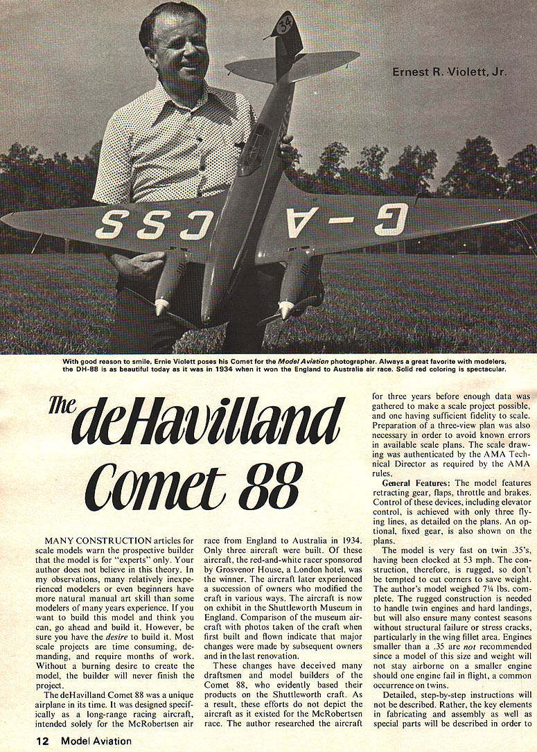
The deHavilland Comet 88 was a unique airplane in its time. It was designed specifically as a long-range racing aircraft, intended solely for the McRobertsen air race from England to Australia in 1934. Only three aircraft were built. Of these aircraft, the red-and-white racer sponsored by Grosvenor House, a London hotel, was the winner. The aircraft later experienced a succession of owners who modified the craft in various ways. The aircraft is now on exhibit in the Shuttleworth Museum in England. Comparison of the museum aircraft with photos taken of the craft when first built and flown indicate that major changes were made by subsequent owners and in the last renovation.
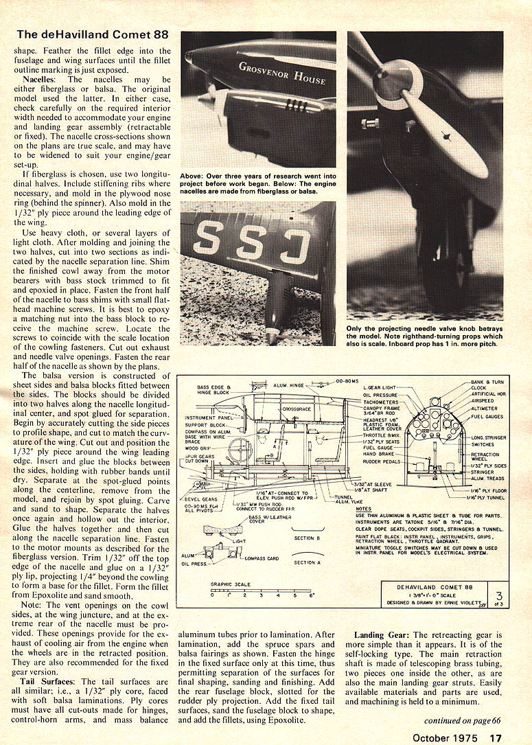
These changes have deceived many draftsmen and model builders of the Comet 88, who evidently based their products on the Shuttleworth craft. As a result, these efforts do not depict the aircraft as it existed for the McRobertsen race. The author researched the aircraft for three years before enough data was gathered to make a scale project possible, and one having sufficient fidelity to scale. Preparation of a three-view plan was also necessary in order to avoid known errors in available scale plans. The scale drawing was authenticated by the AMA Technical Director as required by the AMA rules.
General Features:
The model features retracting gear, flaps, throttle and brakes. Control of these devices, including elevator control, is achieved with only three flying lines, as detailed on the plans. An optional, fixed gear, is also shown on the plans.
The model is very fast on twin .35's, having been clocked at 53 mph. The construction, therefore, is rugged, so don't be tempted to cut corners to save weight. The author's model weighed 7¼ lbs. complete. The rugged construction is needed to handle twin engines and hard landings, but will also ensure many contest seasons without structural failure or stress cracks, particularly in the wing fillet area. Engines smaller than a .35 are not recommended since a model of this size and weight will not stay airborne on a smaller engine should one engine fail in flight, a common occurrence on twins.
Detailed, step-by-step instructions will not be described. Rather, the key elements in fabricating and assembly as well as special parts will be described in order to avoid major errors. A thorough study of the plans and text, however, is a "must do" chore, after which construction should be no problem. The construction sequence is not too important, except where noted. The use of cellulose-acetate type model airplane glues is to be avoided in planking and all exterior joints or seams. Glues of this type continue to dry and shrink over a very long period, causing telltale lines in the finish. An aliphatic resin glue is suggested. The glue used must be sandable, so therefore do not use white glues.
Money can be saved on planking if the planking strips are cut from sheets. However, this is possible only if the builder has access to a small table saw, such as the Unimat, or other suitable devices.
Use medium-weight balsa for all structure members, and use soft, lightweight balsa for planking. Use light (contest-grade) balsa for the tail surfaces. The plywood cores in the tail surfaces and the plywood inlay in the wing trailing edge permit sanding of the trailing edges to a sharp edge without the edge crumbling that would occur with a balsa-only trailing edge. The sharp edge is more to scale than thick edges of balsa.
Wing Construction
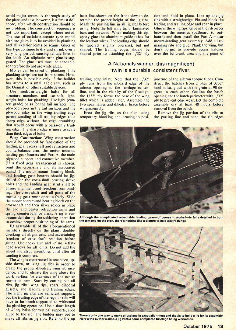
Wing construction should be preceded by fabrication of the landing gear cross shaft and retraction counterbalance arm, the motor mounts, landing gear bearers and Part A, the main plywood support and connective member. (If a fixed gear arrangement is chosen, omit the cross-shaft and its associated parts.) The motor mount, bearing block, and landing gear bearers should be jig-drilled for the cross-shaft bearing sleeve holes and the landing gear strut shaft to ensure alignment and freedom from binding. The cross-shaft and all parts of the retracting gear must operate freely. Slide the motor bearers and bearing block on the cross-shaft and then silver solder in place the end and center retraction arms and spring counterbalance arms. A jig is recommended during the soldering operation to achieve proper positioning of the arms.
Jig assemble all of the aforementioned members directly on the plans, double-checking all alignments, and ascertaining freedom of cross-shaft rotation before gluing. Use epoxy glue and 1/2" No. 4 flat-head screws for all joints. Do not add the wheel and strut assemblies until after all sanding is complete.
The wing is constructed in one piece, upside down, utilizing jig ribs in order to create the proper dihedral, wing rib incidence, and to elevate the wing above the work surface for clearance of the center retraction arm. Start by cutting out all ribs, jig ribs, wing tips, spars, dihedral gussets, and leading and trailing edges. The eight jig ribs are sufficient support, but the trailing edge of the regular ribs will have to be bench-supported to withstand the planking operation. Use a short length of 1/4" sq. balsa for vertical supports, spot glued to the rib. The builder may opt to make all ribs as jig ribs. Refer to the jig base line shown on the front view to determine the proper height of the jig ribs. Mark the parting line in all jig ribs before hinging. Note the left wing tip of laminate bass and plywood. When making this tip, epoxy glue the aluminum guide tubes for the leadout wires. The leading edge should be tapered (slightly oversize), but not shaped. The trailing edges should be shaped prior to attaching the 1/32" ply trailing edge inlay. Note that the 1/32" ply runs from the inboard edge of the aileron opening to the fuselage centerline, and in the vicinity of the fuselage, the 1/32" ply forms the base of the wing fillet which is added later. Assemble the two spar halves and dihedral brace before wing assembly.
Erect the jig ribs on the plan, using temporary blocking and bracing to position and hold in place. Line up the jig ribs with a straightedge. Pin and block the leading and trailing edge and spar in place. Glue in the wing tips. Glue in the rib pieces between the nacelles (outboard to outboard) and then install the Part A motor mount-landing gear assembly. Add all remaining ribs and glue. Plank the wing, but don't forget to provide access hatches over the bellcrank area and the point of juncture of the aileron torque tubes. Construct the hatches from 2 plies of 3/32" hard balsa, glued with the grain at 90 degrees to each other. Outline the hatch opening and the hatch perimeter with 1/32" ply to prevent edge wear. Let the complete assembly dry at least 48 hours before removal from the bench.
Remove the jig portion of the ribs at the parting line and sand the rib edges smooth.
The deHavilland Comet 88
Modify the Roberts bellcrank as described on the plans and install on Part A with blind nuts. Install the throttle, flexible pushrods, deadman crank and stop pin. The over-travel arrangement on the throttle pushrod, detailed on the plans, permits activation of the landing gear switch after full throttle is reached. This switch is a double-pole, double-throw, slide type. The tension spring shown ensures return of the slide to the down position, which takes place upon a slight reduction in the throttle setting.
Install the leadout cables, wing weight, brake flexible pushrod, aluminum tubes for running lights, wiring, and aileron torque tubes. Check all items for secure installation, freedom of moving parts, and electric continuity of wiring. When satisfied everything is in place and in working order, plank the top of the wing. Glue in the filler strip between the aileron and the spar. Make up the aileron ply and balsa sandwiches, and tack glue in place. The nylon hinges should be glued into the ailerons only at this time. Use balsa spacers, spot glued, to achieve the necessary clearance between the ailerons and wing, and center the ply core of the ailerons with the wing trailing edge and the wing tip. When dry, sand the wing to the proper airfoil section using templates to check for accuracy. When sanding is completed, cut the ailerons loose at the glued balsa spacers, and store until finishing begins.
Fuselage Construction:
Begin by cutting out all formers, fuselage sides and part B (two required). Glue a balsa fill piece to the outboard side of the two part B pieces. Shape the filler pieces according to the plan view. Jig construction is recommended. Build a jig of scrap balsa directly over the plan that will maintain vertical alignment of the fuselage sides and establish the fuselage width. Glue the fuselage sides to part B. When dry, insert the sides into the fuselage jig, wedging the sides tight against the jig frame with insertion and gluing of the fuselage formers. Do not forget to insert the flap deadman cranks and cross-shaft when the sides are placed in the jig. Install some temporary diagonal braces between formers (in plan view) to prevent warps when the structure is removed from the jig.
When dry, remove from the jig and install the elevator pushrod, tail skid, all wiring, rudder and elevator controls, flap flexible pushrod, and flap cross-over arm. The bulkhead holes for these devices are not shown on the plans, but are left to the builder's choice in routing. Install the retraction motor support at this time, but not the motor. Construct the battery case from fiberglass cloth and resin, using a dowel slightly larger than battery diameter as a mold. Install battery case and all required contacts and connect to the wiring. Make and fit the dummy interior sides of the cockpit, instrument panel and cockpit floor, but do not install these items. Store until painting is completed. Check all moving parts for freedom, and the wiring for electrical continuity. Plank the top of the fuselage, but not the bottom.
Assemble the fuselage to the wing by inserting the tabs or projections of part B into part A. Glue the tabs well after checking the wing alignment with the fuselage.
Plank the bottom of the fuselage including the retraction gear access hatch area. Fair the bottom planking into the wing, maintaining the fuselage profile. Sand all planking, using cross-section templates to achieve the proper shape. Cut out the access hatch and install suitable formers on the hatch interior face to maintain the shape. Line the hatch opening and the hatch perimeter with 1/32" ply to protect the edges against wear.
Begin the wing fillet construction by marking the fillet outline on the fuselage side and on the top of the wing. Insert a rectangular block in the wing leading edge at the root as shown. Cut the fillet vertical laminations from very soft 3/16" balsa and pin and glue in place one layer at a time. When dry, carve and sand the fillet, using templates to achieve the correct shape. Feather the fillet edge into the fuselage and wing surfaces until the fillet outline marking is just exposed.
Nacelles: The nacelles may be either fiberglass or balsa. The original model used the latter. In either case, check carefully on the required interior width needed to accommodate your engine and landing gear assembly (retractable or fixed). The nacelle cross-sections shown on the plans are true scale, and may have to be widened to suit your engine/gear set-up.
If fiberglass is chosen, use two longitudinal halves. Include stiffening ribs where necessary, and mold in the plywood nose ring (behind the spinner). Also mold in the 1/32" ply piece around the leading edge of the wing.
Use heavy cloth, or several layers of light cloth. After molding and joining the two halves, cut into two sections as indicated by the nacelle separation line. Shim the finished cowl away from the motor bearers with bass stock trimmed to fit and epoxied in place. Fasten the front half of the nacelle to bass shims with small flathead machine screws. It is best to epoxy a matching nut into the bass block to receive the machine screw. Locate the screws to coincide with the scale location of the cowling fasteners. Cut out exhaust and needle valve openings. Fasten the rear half of the nacelle as shown by the plans.
The balsa version is constructed of sheet sides and balsa blocks fitted between the sides. The blocks should be divided into two halves along the nacelle longitudinal center, and spot glued for separation. Begin by accurately cutting the side pieces to profile shape, and cut to match the curvature of the wing. Cut out and position the 1/32" ply piece around the wing leading edge. Insert and glue the blocks between the sides, holding with rubber bands until dry. Separate at the post-glued points along the centerline, remove from the model, and finish to spot gluing. Carve and sand to shape. Separate the halves once again and hollow out the interior. Glue the halves together and then cut along the nacelle separation line. Fasten the motor mounts as described for the fiberglass version. Trim 1/32" off the top edge of the nacelle and glue on a 1/32" ply lip, projecting 1/4" beyond the cowling to form a base for the fillet. Form the fillet from Epoxolite and sand smooth.
Note: The vent openings on the cowl sides, at the wing juncture, and at the extreme rear of the nacelle must be provided. These openings provide for the exhaust of cooling air from the engine when the wheels are in the retracted position. They are also recommended for the fixed gear version.
Tail Surfaces. The tail surfaces are all similar; i.e., a 1/32" ply core, faced with soft balsa laminations. Ply cores must have all cut-outs made for hinges, control-horn arms, and mass balance aluminum tubes prior to lamination. After lamination, add the spruce spars and balsa fairings as shown. Fasten the hinge in the fixed surface only at this time, thus permitting separation of the surfaces for final shaping, sanding and finishing. Add the rear fuselage block, slotted for the rudder ply projection. Add the fixed tail surfaces, sand the fuselage block to shape, and add the fillets, using Epoxolite.
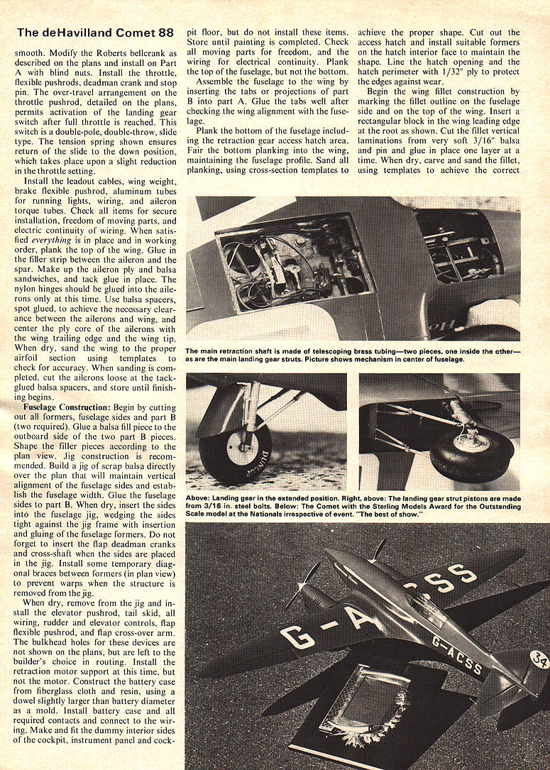
Landing Gear: The retracting gear is more simple than it appears. It is of the self-locking type. The main retraction shaft is made of telescoping brass tubing, two pieces one inside the other, as are also the main landing gear struts. Easily available materials and parts are used, and machining is held to a minimum. control travel of the third line indicator on top of the handle. Provide one stop for the full-throttle position. Movement beyond the stop is to actuate the retraction motor DPDT slide switch in the model by virtue of the throttle overtravel arrangement shown on the plans. Provide a second stop at the other end of the indicator travel for the throttle idle position. Movement beyond the stop is to actuate engine cut-off. Both stops should be hinged to swing out of the way of the indicator. One hand can be used to swing the stops out of the way for gear operation and engine shut-off.
With someone to help you, check the operation of all flying lines, stops, throttles, and the DPDT switch and gear retraction without the engines running and with the flying lines under tension. Repeat the process with one engine running and then with both running. Make any necessary adjustments on the lengths, handle stops, throttle settings or DPDT switch position. If gear operation fails or is erratic when the engines are running, the problem most likely is intermittent or complete loss of electrical continuity caused by vibration. The vibration or loose connection, or whatever the cause, must be eliminated.
For the first flight, and on all flights for testing gear retraction, fly with the nacelles and wheel spats removed. If a wheels-up, belly landing is needed, the model will land undamaged. Otherwise, the nacelles would be wiped out. Some glo-plug damage may be incurred, but this is a minor matter.
Use a little upright aileron to achieve level flight. Use masking tape to hold the aileron in position. Also tape the canopy down as a precaution on all flights. Use a clear tape when in competition.
Pick a smooth, even flying surface. This is a must since the model will flip on its nose easily on a rough surface.
Conduct a successful pull-test, and you're ready for the maiden flight. To get the engines running correctly, start the outboard engine and tune to the best rpm by ear or by a reed tachometer. Stop the engine and then repeat the operation on the inboard engine. With it running smoothly, restart the outboard engine. Do any required "tweaking" of the needle valves to be sure engines are synchronized as closely as possible. With a helper holding the plane, reduce the engine rpm (from the control handle) to about the 40% level and release the plane. Hold the plane on the ground, gradually opening the throttle. Don't lift the plane off—let it lift off by virtue of sufficient flying speed. The rest is easy. The plane is fast, but grooves easily. To land, reduce engine rpm slowly and let the plane speed decrease. With the plane flying as slowly as possible, lose altitude slowly and when very close to the ground, reduce the throttle slightly and the model will set down. To reduce the landing roll, or to stop, apply the brake by using full up elevator. Move the third-line control to the engine shut-off position.
Check the aircraft thoroughly after the first flight and every flight thereafter, for damage, stress cracks, loose nuts, fittings, wheels, engines and control surfaces. With reasonable care, this model is capable of five to seven years competition life.
The author wishes to extend his appreciation to Bill Harris of Laurel, Md., for his skillful help in preparing the Comet for competition and for acting as "pit" man in many past Nationals.
(Editor's Note: Extensive information — a Scale Information Sheet — accompanies the plans, as does a scale authentication board. This information is provided for all those who consider entering the model in competition — such information is required for judging, proof of scale, etc.)
Transcribed from original scans by AI. Minor OCR errors may remain.

