
DEHAVILLAND MOSQUITO
Jack Sheeks
Overview / History
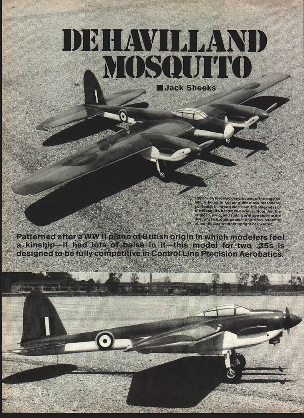
Nicknamed the "termite's dream" and the "wooden wonder" because of its plywood construction, the De Havilland Mosquito was developed during the dark days of 1939–1940. England needed a fast, high-altitude bomber and reconnaissance aircraft capable of deep penetration; the Mosquito was designed to be so fast that it wouldn't need heavy armament. When it entered service it was faster than any fighter either side could put up, with a loaded speed of about 382 mph. Designers still left room under the floor for four 20 mm cannons.
There were 7,781 Mosquitoes built in England, Canada, and Australia in some 41 different models. The full-size aircraft had a wingspan of 54 ft. 2 in., weighed 19,670 lb., and was powered by two 1,460-hp Rolls-Royce Merlin engines. Its construction included balsa sandwiched between plywood sheeting.
When the first Mosquito rolled out, VIPs watched it perform vertical rolls from ground level with one engine feathered and recorded speeds over 400 mph. German intelligence even parachuted a man into England with a camera to see it; he was captured the next day.
If there is such a thing as the best, the Mosquito has to be one of the best all-around twins to come out of WWII.
Why the model
This control-line model, designed for two .35 engines, is intended to be fully competitive in Precision Aerobatics (Stunt). I've been building and flying twin Stunters for close to 20 years. Some were published in Flying Models magazine; others have met the blacktop. Some models were very good, some duds. I learned a little from each, and tried to apply that education to the Mossie.
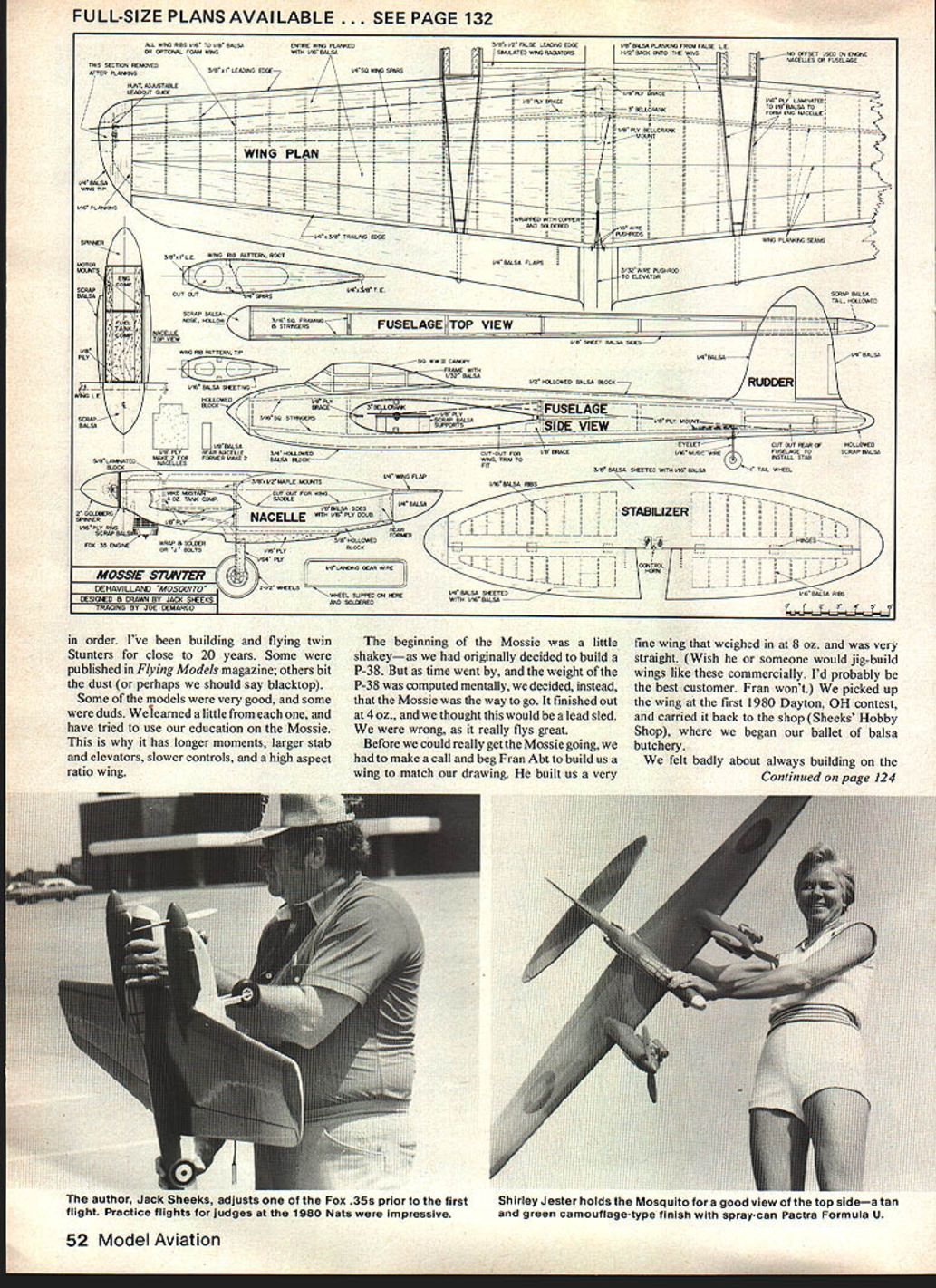
The model ended up with longer moments, larger stabilizer and elevators, slower controls, and a high-aspect-ratio wing. I originally planned a P-38, but weight estimates pushed me to the Mossie. I finished out at about 4 lb and thought it would be a lead sled—wrong. It really flies great.
Development and flight testing
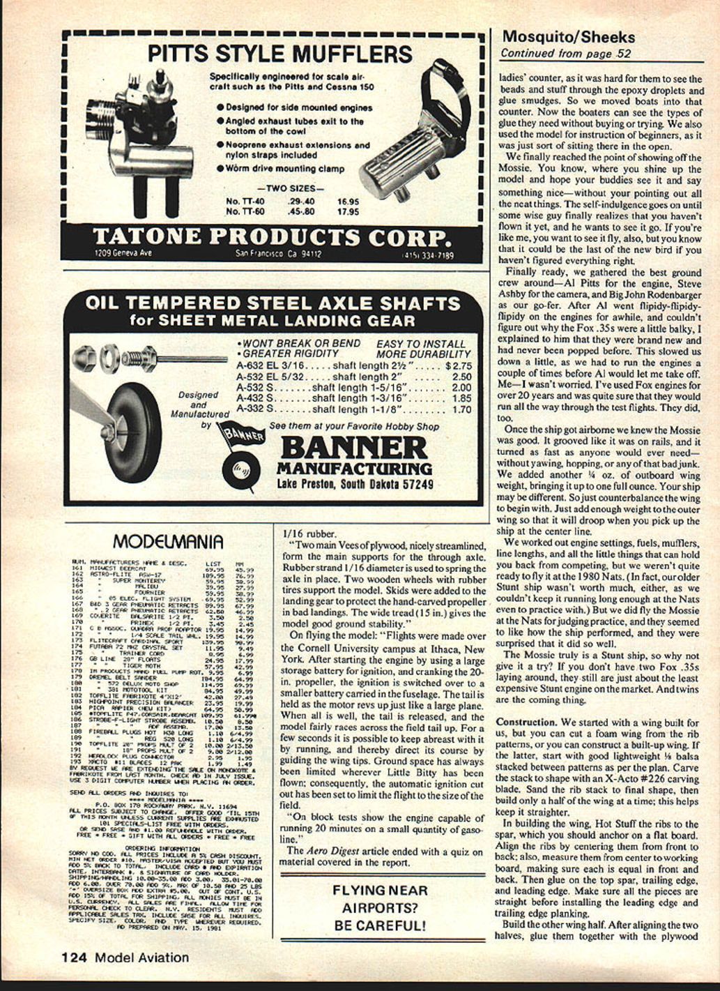
Before proceeding I had to get a proper wing built to the drawing, so I begged Fran Abt to build one. He produced a very fine wing that weighed 8 oz and was exceptionally straight. Wish someone would jig-build wings like that commercially—I'd be their best customer.
We prepped, polished, and finally showed off the Mossie. The usual ritual followed: admire it on the ground, then someone asks to see it fly. We assembled the best ground crew—Al Pitts for engines, Steve Ashby for camera, and Big John Rodenbarger as go-fer. Al had to run the new Fox .35s a couple of times to break them in; they are engines I've relied on for over 20 years, and they ran through the tests fine.
Once airborne the Mossie grooved like it was on rails and turned as fast as anyone would need—without yawing or hopping. We added another 1/4 oz of outboard wing weight (bringing it to about 1 oz outboard) to ensure the outer panels drooped slightly when the model is picked up at the center line. Your ship may differ, so counterbalance the wing to begin with and adjust as needed.
We worked out engine settings, fuels, mufflers, line lengths, and other small but critical items before contesting. The Mossie is truly a Stunt ship and worth trying. If you don't have two Fox .35s, they remain among the least expensive Stunt engines on the market. Twins are the coming thing.
Construction
General notes
You can build the wing from foam using the rib patterns, or construct a built-up balsa wing. If you build a balsa wing, start with good lightweight balsa stacked between rib patterns and carve the stack to shape with an X-Acto #226 carving blade. Sand the rib stack to final shape, then build only half the wing at a time—this helps keep it straight.
Anchor the spar on a flat board and attach ribs with Hot Stuff (or equivalent). Align ribs by centering them front to back and by measuring from the center to the working board so each rib is positioned equally in front and back. Glue on the top spar, trailing edge, and leading edge, making sure all pieces are straight before installing the leading- and trailing-edge planking.
Build the other wing half. After aligning the two halves, glue them together with the plywood dihedral brace. I used a two-piece brace—one in each panel—made from 1/8-in. plywood. Then sheet the wing bottom with 1/16-in. balsa. Carve and sand the tip ribs to produce the proper tip shape. Add the ailerons per plan and hinge them with 1/8-in.-wide hinges, beveling hinge lines as needed.
Leave off the top planking until you install the bellcrank, leadouts, and pushrod to the flaps. After installing those controls you can finish sheeting the wing, install the tips (with adjustable leadouts), install the flaps (pin the hinges), and hook up the controls. Make sure everything works smoothly—this gives you a complete working wing.
Nacelles and engines
- Cut out four nacelle sides from 1/4-in. balsa and the 1/16-in. plywood doublers.
- Glue these together along with the 3/8 x 1/2 motor mounts.
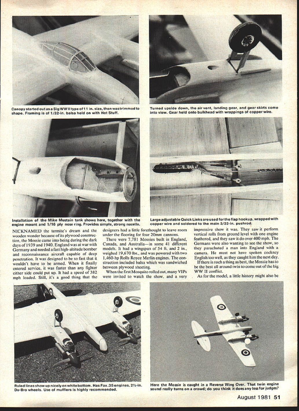
- The formers for the prototype nacelles were cut to fit two Mike Mustain custom 3-1/2-oz. fuel tanks—an excellent product. Fit and glue these pieces around the tanks.
- Drill the motor mounts and install blind nuts to fit two Fox .35s.
- Mount the nacelles on the wing with epoxy. No extra doublers were used—keep it light.
Fuselage and tail
- Build the fuselage from 1/8-in. sheet and 3/16-in. square stock.
- Align the wing with the fuselage top and side views, and glue it in place before installing the top and bottom fuselage blocks.
- While glue sets, build the horizontal tail surfaces.
- When stabilizer and elevators are assembled and glue is dry, sand to shape, then install control horn and hinges. Solder pushrod on, and slide the completed stabilizer into place.
- Wrap wing flap and elevator pushrods together with copper wire and solder. Slide the stabilizer back and forth until it aligns horizontally with the pinned flaps (use the centerline used to align the wing and fuselage). Wing, stab, and engine bearers must be perfectly aligned to ensure the ship grooves properly.
Landing gear and small parts
- Landing gear: use 5/8-in. music wire mounted on the plywood nacelle formers by wrapping with copper wire—lightweight and less bulky than other methods.
- Tail wheel: mount similarly.
- Shape the nose of the nacelles to conform to a 2-in. spinner, filling as necessary with scrap balsa.
- Nose and tail blocks: build from scrap balsa and hollow out as much as possible. Tack-glue blocks on, carve to shape, pop off and hollow, then glue them on permanently and sand smooth.
Canopy and details
- Use an 11-in. Sig WWII canopy cut and fitted, then frame with 1/32-in. balsa.
- Install a 1/4-in. balsa rudder tab (it’s easily broken off without the larger tab).
- Make fillets with a mix of talcum powder and dope, then do final sanding.
Finishing
Our finishing process:
- Smear on a coat of Hobbypoxy Formula II, then scrape off as much as possible with a plastic playing card. Protect control areas with a thin coat of heated Vaseline to keep epoxy out—be careful to avoid contamination.
- Sand the first coat with 320 wet-or-dry sandpaper, then apply a second coat of Hobbypoxy.
- After sanding again, apply two coats of K&B Super Poxy Primer, sanding between coats.
- Final finish: Pactra Formula U from spray cans—tan and green on top surfaces, white on the bottom.
- Decals: use Bob Dively Model Aircraft Co. decals (or equivalent).
Final setup and tips
- Balance the wing panels so the outer panels droop slightly when lifting at the center line—this helps handling.
- Break in new engines before flying for performance consistency.
- Work out engine settings, fuel, mufflers, and line lengths on the ground before contest flying.
- Make sure bellcrank, leadouts, and pushrods operate smoothly and are secured before final sheeting.
- Keep components (wing, stab, engine bearers) aligned to ensure the model grooves straight.
Anecdotes and shop notes
We felt self-indulgent polishing and showing the Mossie until someone finally asked to see it fly. We originally built much of the work on the shop counter and felt bad about epoxy smudges and so on, so we moved the boaters into that counter area so they could see the glues they needed and get instruction. The Mossie was also used to instruct beginners.
Fran Abt picked up the wing at the 1980 Dayton, OH contest and carried it back to his shop. Sheeks Hobby Shop then did the final balsa work.
Conclusion / Invitation
Give the Mossie a try—you won't be sorry. If you're ever in Indianapolis, look us up at Sheeks' Hobby Shop and stop by. We may have something spread out, and you can join us in a kibitzing session.
Transcribed from original scans by AI. Minor OCR errors may remain.

