
Delilah
This twin-.020-powered flying boat is at home in the air and in the water.
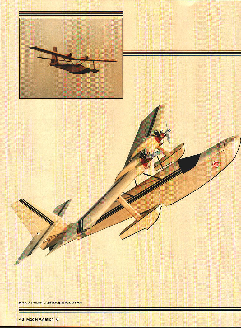
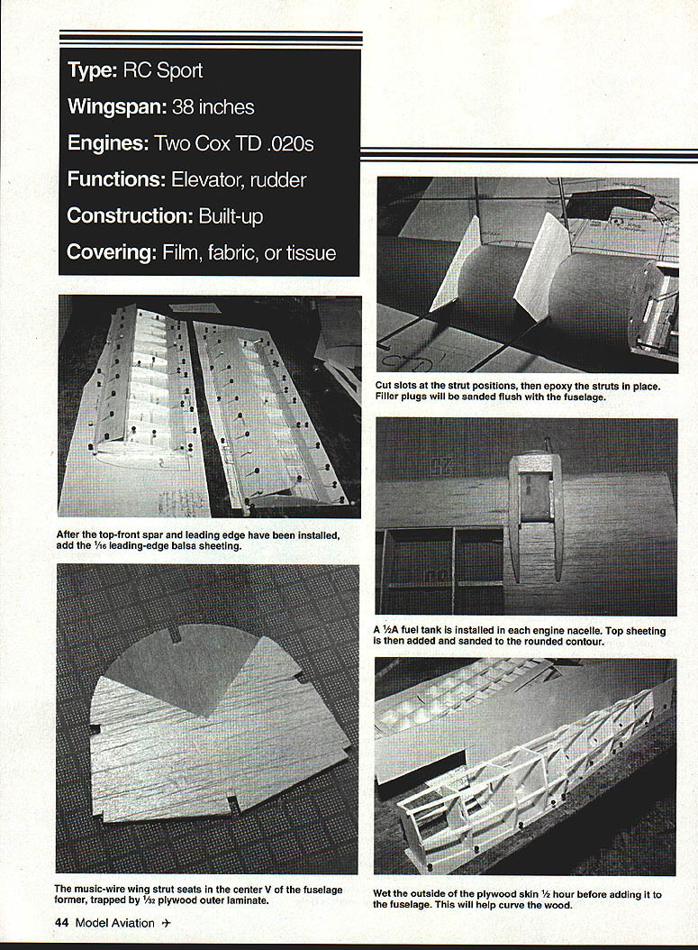
If you are looking for a model that's versatile, small, maneuverable, exciting, and different, Delilah will fit the bill. Delilah is a 38" span twin-engined flying boat, powered by Cox Tee Dee .020s. She's a flighty piece of work but handles like a thoroughbred.
I was inspired by an old copy of Radio Control Models & Electronics (RCM&E) that showed my earlier design, the Seastormer. Although the Seastormer handled well in the air, it was not entirely at ease on the water — I had not made the fuselage wide enough or given it sufficient nose extension. I realized that combining several elements — a parasol wing arrangement with engines close to the centreline, a rolled-plywood fuselage with a wider beam, and a longer nose moment — might produce a pleasant flying boat. Water airplanes have always fascinated me.
Designing radio-control model aircraft challenges you to create an airplane that is structurally sound and that flies well. I prefer to have everything drawn and organized before building, including radio equipment location, linkages, fuel tank, and engine installation. During construction I often find things I would do differently next time; that is one advantage of publishing plans and articles — improvements can be incorporated into final drawings. Rolled-plywood structures have some restrictions, particularly when changing fuselage widths or supporting framework, but once finished they are extremely strong and quite light. Given the experimental nature of the project, I decided to build a small-scale version before moving on to larger versions.
David Boddington
"Just the sound of two Cox .020s in-beat makes it all worthwhile."
- David Boddington
CONSTRUCTION
Already, with Delilah (and in preparation for the larger Samson), a few improvements were found during building and have been incorporated into the drawings. Note the following changes and tips:
- Constructing the fuselage framework at the front end, as originally designed, was somewhat akin to building sand castles in the air. Provisionally extend the spine and the tops of formers F1 and F2 (spot-cemented in place) so it's much easier to construct the framework inverted over the board. Pin a flat-topped temporary former to the outside of F10 to help make the framework rigid on the building board.
- Fitting the front wing struts to the undersides of the engine nacelles is fiddly and requires bolts and nylon saddles. The fuel-tank bay is tight, so I extended the engine nacelles slightly and moved the front strut more upright so the nylon saddles can be screwed directly into the underside nacelle plywood without fear of piercing the fuel tank.
- A near-disaster occurred with the rudder cables. The closed-loop control linkage and wing struts are fitted after fuselage construction, but earlier drawings routed the cables through the "V" centre where the struts are housed. Because the cables had been fitted before completion of the fuselage, it would have been impossible to fit the rear strut. Rerouting the cables through small-bore tubing cured the problem.
General Comments
- Cut out all parts and form the struts before assembly.
- 1/64" plywood may seem thin, but it is strong enough for a model this size.
- Use waterproof adhesives; Cyanoacrylate (CyA) and epoxy are suitable. Thorough waterproofing is essential.
- Seal the elevator pushrod exit with silicone rubber sealant; apply petroleum jelly to the metal rod where the sealant is positioned to prevent sticking. Pay special attention to the front hatch.
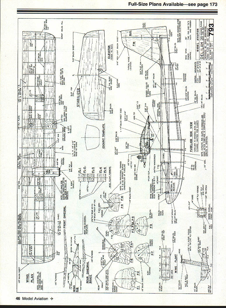
Wing Design
The chosen airfoil allows you to build the wing panels directly over the drawing.
- Pin down the lower trailing edge, the rear spar, and the lower main spar, then locate and pin the wing ribs.
- The 1/16" plywood nacelle plate should NOT be glued in place at this stage; fit it only after the wing panel has been shaped.
- Glue the top trailing edge, the top main spar, the leading-edge strip, and the ribs. Set the root rib at the correct dihedral angle and add vertical webbing to the leading-edge centre-section sheeting. Leave to dry before removing from the board.
- Sand the leading edge to section and carefully cut away the leading-edge sheeting back to the main spars at the engine nacelle position.
- Glue 1/4" nacelle sides to the wing panel, plus the 1/16" plywood underside, 1/16" front sheet, 3/16" triangular filler, 7/8" x 5/8" top reinforcement, and then the 1/8" plywood engine bulkhead. To improve single-engine performance, include 3–4° right thrust to the starboard engine.
- Sew 3/32" tubing to the 1/16" rear strut mounting plate, epoxy (or CyA) around the tubing and sewing, and glue to the wing panels, reinforcing with balsa strips. File holes in the front of the engine nacelles for the fuel-feed tubing and fuel-proof the inside of the tank bay. When dry, fit the 1/2A fuel tanks, with fuel feed fitted, and wedge them in position with balsa scrap. Fix the top 3/32" sheeting and rear fairing, and shape the nacelles by rounding off the corners.
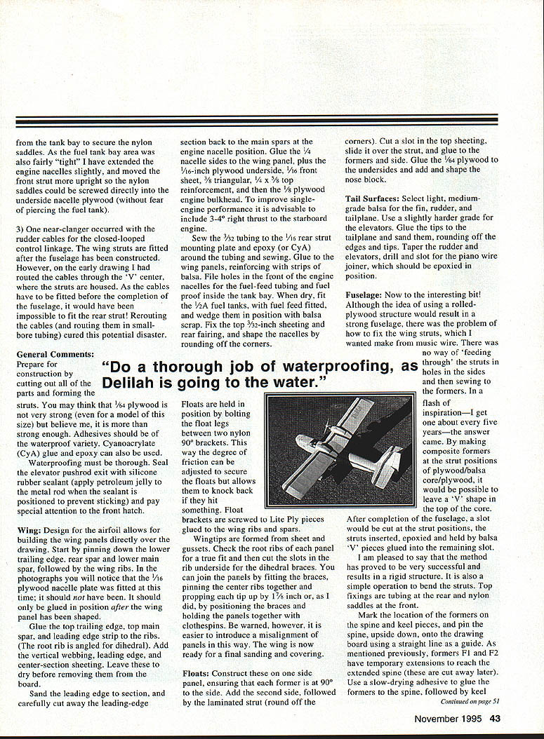
Floats are held by bolting the float legs between two nylon 90° brackets. This arrangement provides friction that secures the floats but allows them to knock back if they hit something. Float brackets are screwed to Liteply pieces glued to the wing ribs and spars.
Wingtips are formed from sheet and gussets. Check root ribs for true fit and cut the slots in the rib undersides for the dihedral braces. Join panels by fitting the braces, pinning the center ribs together and propping each tip up by 1/8", or by positioning the braces and holding the panels together with clothespins (but beware of introducing misalignment). The wing is now ready for final sanding and covering.
Floats
- Construct on one side panel, ensuring each former is at 90° to the side.
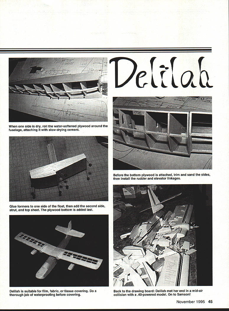
- Add the second side, followed by the laminated strut (round off the corners).
- Cut a slot in the top sheeting, slide it over the strut, and glue to the formers and side.
- Glue 1/64" plywood to the undersides and add and shape the nose block.
Tail Surfaces
- Select light, medium-grade balsa for the fin, rudder, and tailplane; use slightly harder balsa for the elevators.
- Glue the tips to the tailplane and sand, rounding off edges and tips. Taper the rudder and elevators.
- Drill and slot for the piano-wire joiner, which should be epoxied in position.
Fuselage
The rolled-plywood fuselage gives excellent strength, but fixing the wing struts (from music wire) posed a problem — the struts couldn't be fed through side holes and sewn to formers. The solution was composite formers at the strut positions (plywood / balsa core / plywood) that leave a "V" shape in the top of the core. After fuselage completion, cut slots at the strut positions, insert the struts, epoxy and secure with balsa "V" pieces glued into the remaining slot. This yields a rigid structure; top fixings are tubing at the rear and nylon saddles at the front.
- Mark the formers on the spine and keel pieces and pin the spine (upside down) to the board using a straight line as a guide. Formers F1 and F2 have temporary extensions to reach the extended spine (these are cut away later). Use slow-drying adhesive to glue formers to the spine, then add keel pieces and pin in position. Also glue the 1/8" x 3/16" side stringers and 1/8" square longerons. Check former angles; F10 has a flat-topped support pinned to the outside to prevent movement on the board. Glue 3/32" sheet between F1 and F10.
- When the framework is dry, remove it from the board and sand the former sides flush with the stringers, longerons, and spine. Cut a piece of 1/4" plywood 26" long (grain lengthwise) and 9" wide. At the center of one end cut out a panel 5-1/4" long and 4" wide for the hatch and cockpit. Mark a 1/8" line down the center of the plywood and glue the spine to this, aligning the front edge of F3 with the cutout. Leave to dry.
- Using slow-drying cement, glue one side of the plywood to the framework. Wetting the outside of the plywood about 30 minutes before fixing helps with curving. Ensure the side is attached at all points except the nose from F1 to near F3 (this area is glued later). Pin the side to the board and leave to dry, then repeat for the other side. Finally glue and pin the plywood to the front formers.
- Before attaching the bottom plywood, trim and sand the lower edges of the sides and install the rudder and elevator linkages. The rudder closed-loop (20 lb-test nylon-covered fishing trace) should be routed through narrow-gauge nylon tubing. Use a standard pushrod for the elevator linkage, or a small-diameter "snake" type; avoid oversized tubing (3/16" O.D. tubing looks wrong for a small model). With the bottom sheet in place, fit the nose block and form the hatch and cockpit. Cut the slots for the struts (positions as per drawings), dry-fit everything, then epoxy the struts in place and add 3/32" balsa filler to fair them into the fuselage profile.
Finishing
- Delilah is suitable for film, fabric, or tissue covering.
- Do a thorough job of sealing and waterproofing before covering — she will be taking to the water.
- Cover the fin, rudder, tailplane, and elevator separately before joining the fin and tailplane. Hinge the elevators first, then the rudder. Glue the tail assembly to the fuselage and support the fin with triangular gussets.
Radio
- There is ample room in the bays between F1–F2 and F2–F3 for standard-size radio gear.
- I omitted an internal antenna tube and had to route the aerial to the top of the fin; fit an internal switch and arrange for remote access to the toggle.
Flying
- Perform standard checks for balance, radio operation, and correct control directions. For first flights, hand launches are recommended — water flying can come later.
- The model will fly on one engine and has a respectable glide. It is preferable if the starboard engine cuts first to minimize torque effect. Always start the starboard engine first, and top off the port fuel tank before launching.
My maiden flight story: completing Delilah just as winter approached was not ideal, but a fine, sunny afternoon and a layer of snow tempted us out. Neither Cox .020 had been run before, yet both started surprisingly well in the cold with help from a small electric starter. On the first attempt, with needle valves set very rich, the model failed to gain height and ended up skipping into a thorn bush; only a few punctures resulted and the starboard float was knocked back — the friction-bolt float fitting proved effective.
On the next attempt, with engines at full power, Delilah flew beautifully. Despite a slightly forward centre of gravity and light up-elevator trim, handling was responsive. One starboard engine cut during a flyby, and Delilah remained controllable on a single engine, though turning to port (into the live engine) was marginal; full-left rudder trim cured this. Handling was so good I continued the photo session on one engine — in a straight line she climbs steadily on one engine.
Control movements used on the maiden flight were about 3/8" elevator up/down and just over 1/2" rudder left/right. Rudder authority was barely sufficient with one engine. I recommend:
- With rates on: 1/2" rudder each way.
- With rates off: 3/4" rudder each way.
This gives ample rudder movement regardless of which engine cuts when rates are switched out. The CG may be safely moved rearward slightly, but I did not bother as the model flew well as set.
After numerous excellent flights, Delilah met her end in a full-frontal midair collision with a .40-powered model during an Old Warden Fly-In. She was badly cut up and one Cox .020 engine was lost. The accident did, however, spur me to begin building Samson.
Transcribed from original scans by AI. Minor OCR errors may remain.

