
The Derringer
Clarence Haught
Introduction
In the early years of aviation, many flights were terminated due to engine failure. Pioneers were quick to realize the safety factor of multiple engines. Weight, maneuverability, and cost, however, were limiting factors. Single-engine aircraft continued to dominate private and small-business aviation until the advent of the so-called "light twins" introduced in the 1950s.
Since that time, there have been a multitude of small twin-engine aircraft offered, at least one with a push-pull engine arrangement, and even a four-engine version by Cessna. Most were designed to carry a minimum of five people up to a dozen.
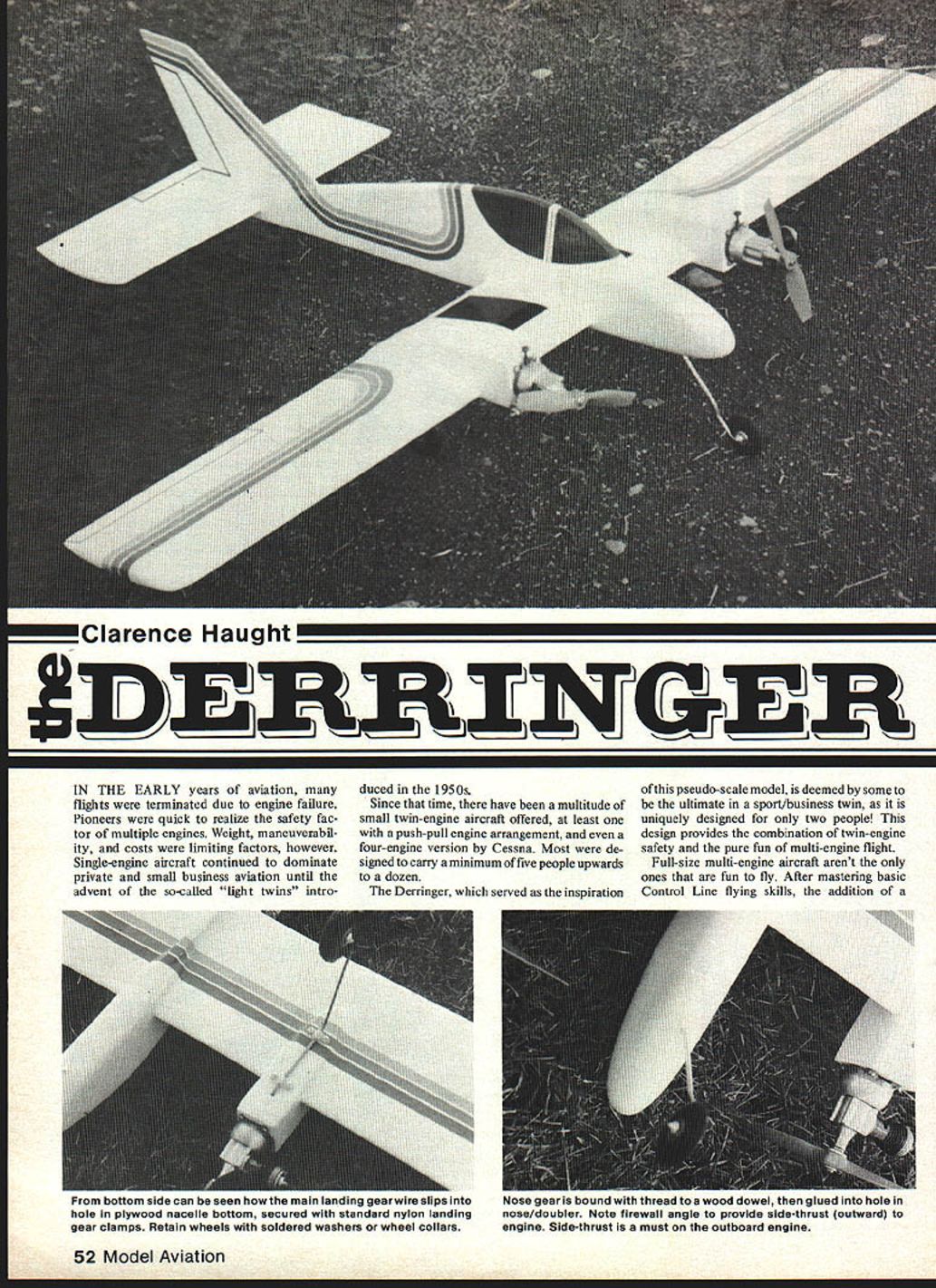
The Derringer, which served as the inspiration for this pseudo-scale model, is deemed by some to be the ultimate sport/business twin, as it is uniquely designed for only two people. This design provides the combination of twin-engine safety and the pure fun of multi-engine flight.
Full-size multi-engine aircraft aren't the only ones that are fun to fly. After mastering basic Control Line flying skills, the addition of a second power plant adds new excitement to modeling. First, there is the neat sound of two engines working in unison; then there's the challenge of maintaining flight on one engine, as fuel is exhausted on one engine before the other; and finally, there is the joy of having something a bit different on the flying field. My son and I have enjoyed multi-engine 1/2A Control Line for many years, beginning with an old converted-to-twin Ambroid Whipsaw—to a DC-3, an Me 110, a Bell X-P twin pusher, and finally, the Derringer.
The Derringer is intended for a first venture into the world of multi-engine Control Line flight. It has been designed for ease of construction and, most important, accurate alignment of all components. The basic model is constructed right over the plan and pinned to the building board until the final stages of construction. Any modeler who has completed one or two kits and has mastered basic flying and engine-operating skills should be ready for the Derringer.
Construction
Wing
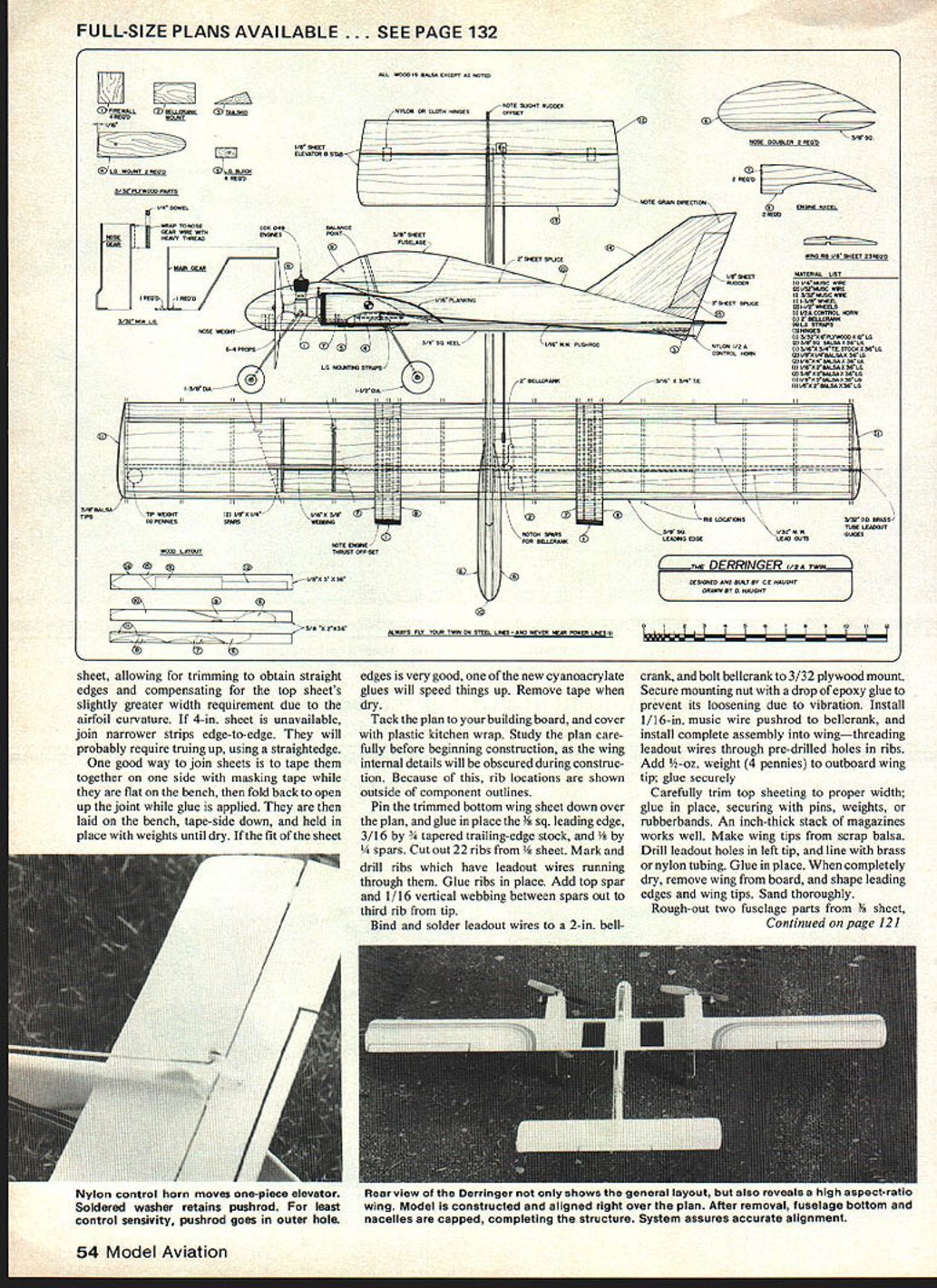
Begin construction with the wing. The chord was designed to utilize 4-in. sheet, allowing trimming to obtain straight edges; compensating top sheets may require slightly greater width due to airfoil curvature. If 4-in. sheet is unavailable, join narrower strips edge-to-edge; you will probably need to true them up using a straightedge. A good way to join sheets is to tape them together side-to-side with masking tape on the flat bench, fold back, open the joint, apply glue, and lay the joint tape-side down, holding in place with weights until dry. If the fit of the sheet edges is very good, one of the new cyanoacrylate glues will speed things up. Remove tape when dry.
Tack the plan to your building board and cover with plastic kitchen wrap. Study the plan carefully before beginning construction, as the wing internal details will be obscured during construction. Because of this, rib locations are shown outside of component outlines.
Pin the trimmed bottom wing sheet down over the plan, and glue in place the 3/16-in. sq. leading edge, 3/16-in. by 1/4-in. tapered trailing-edge stock, and 3/8-in. by 1/4-in. spars. Cut out 22 ribs from 1/8-in. sheet. Mark and drill ribs that have leadout wires running through them. Glue ribs in place. Add the top spar and 1/16-in. vertical webbing between spars out to the third rib from the tip.
Make wing tips from scrap balsa. Drill leadout holes in the left tip and line with brass or nylon tubing; glue in place. When completely dry, remove the wing from the board and shape leading edges and wing tips. Sand thoroughly.
Bellcrank and Leadouts
Bind and solder leadout wires to a 2-in. bellcrank, and bolt the bellcrank to a 3/32-in. plywood mount. Secure the mounting nut with a drop of epoxy glue to prevent loosening due to vibration. Install a 1/16-in. music-wire pushrod to the bellcrank, and install the complete assembly into the wing—threading leadout wires through the pre-drilled holes in the ribs. Add 1/2-oz. weight (four pennies) to the outboard wing tip; glue securely.
Carefully trim top sheeting to proper width and glue in place, securing with pins, weights, or rubber bands (an inch-thick stack of magazines works well). Drill leadout holes in the left tip and line with tubing as noted above.
Fuselage and Tail
Rough out two fuselage parts from 1/8-in. sheet and glue together at the seam line. When dry, complete shaping. Wrap sandpaper over the top of the wing and use the wing as a sanding block to finish the wing saddle in the fuselage. This is best accomplished with the wing secured to the bench and moving the fuselage back and forth sideways over the sandpaper.
Cut out and shape stabilizer and elevators from 1/8-in. sheet. Elevators may be joined to the stabilizer at this time, using three of your favorite hinges. Join and shape rudder parts.
Final Assembly
Begin final assembly by pinning wing and stabilizer in place over the plan. Glue the fuselage in position, being sure it is perpendicular to the plane (check with a square or small triangle). Sand rear edges of fuselage doublers to shape and glue in place. Install engine nacelle sides and 1/16-in. sheet over the top. Be careful not to cover any pins securing structure to the building board!
Glue the rudder in place, offsetting the leading edge to the left (looking from the rear). Be sure it is vertical by checking with a square. Allow to dry thoroughly, and remove from the building board.
Nacelles and Firewalls
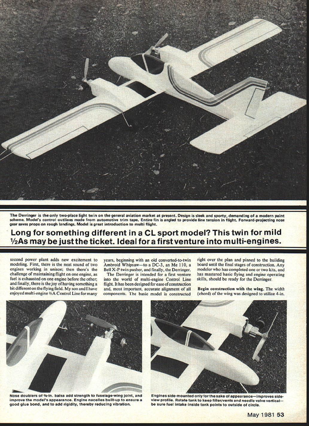
Cut engine nacelle bottoms from 3/32-in. plywood. Note small blocks which receive landing gear wires; these may be solid hardwood or laminated scraps of plywood. All edges of nacelle bottoms should be beveled, except the leading edge. Glue in place under the wing and to nacelle sides. Install a 1/4-in. square strip to the fuselage bottom and doublers. Note the angle of firewalls and nacelles relative to this angle. Nacelles may be built straight if desired, but the angle shown for the outboard engine is important to maintain line tension if the inboard engine quits first in flight.
Firewalls are made by laminating two pieces of 3/32-in. plywood or by using a single piece of 1/4-in. plywood. Glue securely with epoxy.
Landing Gear
Bend landing gear parts from 3/32-in. music wire. Bind the nose gear wire to a piece of 3/16-in. dowel with heavy thread or fine wire. Drill a hole in the fuselage to accept the nose gear—this is best accomplished with a piece of sharpened brass tubing rather than a drill bit to avoid accidental splitting or chipping. Coat the assembly with epoxy glue and push into place.
Finishing
Give the model a final sanding, and proceed with your favorite finish. A traditional fuel-proof dope is recommended. Fill any imperfections with plastic balsa. Give the complete model two coats of clear dope, sanding lightly after each coat.
Apply a coat of commercial sanding sealer, or make your own by adding talcum powder to clear dope until it is the consistency of cream. Sand this coat almost completely away, leaving only filler in the wood grain. Add two more coats of clear. You should now have a good base for your color finish.
Brush or, preferably, spray on a couple coats of your basic color. (Dope sold in aerosol cans works great for a small model like this.) Let the basic finish dry for a couple of days before adding trim.
Trim and Final Touches
Trim may be either painted on using masking tape or applied with plastic trim tapes. When trimming with dope, use a brush to avoid masking the entire model. If you paint on the trim, be sure to seal the edges of the masking tape with clear dope; this prevents paint from seeping under the tape and spoiling the job. Striping tape works well for control-surface outlines. A coat of paste wax will protect trim tapes.
Install main landing gear wires, securing with nylon straps and screws. Secure wheels with collars or soldered washers. Bolt a nylon control horn to the elevator and hook up pushrods. Check control movement. Place the control rod in one of the outer holes of the elevator horn to reduce control sensitivity. Form loops on leadout wires; bind with copper wire and solder.
Engines, Balance, and Propellers
Attach engines to firewalls with #3 x 1/2-in. metal screws. If engines are not mounted upright, remove tanks and place fuel-feed lines toward the outside of the flight circle; reinstall tanks with filler tubes vertical. Install 6-in. propellers with 3-in. pitch.
Recommended engines:
- Cox Baby Bee (original model)
- Cox Golden Bee (gives longer flights)
- McCoy .049 (should work equally well)
- Cox Black Widow (probably too much power)
Check the balance point as shown on the plan. Do not try to fly even a slightly tail-heavy airplane; it will be very sensitive and difficult to control. A slightly nose-heavy model is safe to fly but will be sluggish. Add ballast if necessary to bring the model into balance:
- Tail weight may be epoxied to the fuselage side under the stabilizer.
- Nose weight is best inserted into a hole in the nose doublers cut with a sharpened piece of brass tubing.
Flying
Flying your Derringer is much like flying any other model, but there are a few precautions and differences you need to consider.
- Never fly on anything but metal lines. Fabric lines as used for 1/2A sport flying will not hold a twin. Ideal size: .008-in. multistrand by 35-ft.
- Fuel and prime both engines before starting the first engine. Use a fuel bulb (or another system) to top off both tanks while the engines are running—just before releasing the model.
- Start the inboard engine first so that you will not be reaching over a running engine while starting the second one.
- Tune engines to just under their peak RPM. Be sure both engines are running in the right direction by checking breeze off the prop.
- Keep a rag handy to toss into the prop to stop the engines if the need arises.
A basic concern of multi-engine flight is the airplane's behavior with one dead engine. As long as line tension is maintained, single-engine performance will be satisfactory. If the outboard engine quits first, line tension is no problem. If the inboard engine quits first, the outboard engine will maintain line tension if it has the proper side-thrust as shown on the plans.
The speed/performance of the Derringer is directly related to engine-propeller combinations. If your model seems too fast, experiment with shorter-diameter or lower-pitch propellers. Cox makes a nice three-blade prop which works well and looks great with their rubber spinner. This combination is convenient with an electric starter, which also eliminates the problem of the engine running backwards.
Pick a calm day for test flights—and enter a new stage of aeromodelling!
Transcribed from original scans by AI. Minor OCR errors may remain.

