
Designing the Imitation
Editor's Note: In order to reinforce the reader's impressions of the author's discussion of design development, we "borrowed" many of the photos that were intended for next month's construction feature and plans. They will not be repeated—so be sure to keep this issue for reference. Both installments include a vast amount of priceless information relating to all these photos and our necessarily generalized captions do not, in this instance, do justice to the author, or to the knowledgeable stunt flier.
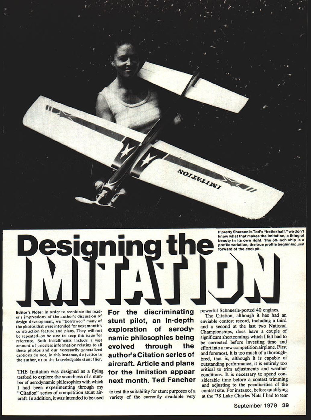
For the discriminating stunt pilot, an in-depth exploration of aerodynamic philosophies being evolved through the author's Citation series of aircraft. Article and plans for the Imitation appear next month. Ted Fancher
The Imitation was designed as a flying testbed to explore the soundness of a number of aerodynamic philosophies with which I had been experimenting through my "Citation" series of competition stunt aircraft. In addition, it was intended to be used to test the suitability for stunt purposes of a variety of the currently available very powerful Schnuerle-ported .40 engines.
The Citation, although it has had an enviable contest record, including a third and a second at the last two National Championships, does have a couple of significant shortcomings which I felt had to be corrected before investing time and effort into a new competition airplane. First and foremost, it is too much of a thoroughbred. Although capable of outstanding performance, it is entirely too critical to trim adjustments and weather conditions. It is necessary to spend considerable time before a contest trimming and adjusting to the peculiarities of the contest site. For instance, before qualifying at the 1978 Lake Charles Nats I had to tear out almost a full ounce of nose weight in order to regain the same degree of crispness in corners that I had had in the cool, heavy air of Northern California. In addition, it was necessary to explore a whole series of props to find one which would allow crisp maneuvers without resulting in excessive airspeeds. The single most perplexing problem, however, is the Citation's inability to come out of a corner hard and flat every time. It is altogether too sensitive to handle adjustment and center of gravity location, and has to be literally nursed around corners if an occasional bobble is to be avoided.
Because of the need to resolve these problems I decided to design an easily built test ship which would allow me to investigate possible solutions. To be meaningful, such a design would have to combine ease of construction with a truly competitive planform which would, as nearly as possible, display the characteristics of a state-of-the-art competition stunt plane. Such a combination would have to include:
- An inverted engine with an appropriately located fuel system, i.e., directly behind the engine and adjustable in the vertical to allow trimming for consistent engine runs.
- The ability to easily interchange engines to explore potential replacements for the venerable ST 46.
- A planform—wing span, wing area, moment arms, horizontal stab and elevator area, aspect ratios, etc.—identical to a competition plane of the same size.
- Avoiding the temptation to make the Imitation significantly lighter than a competition ship; a lighter wing loading would make test results meaningless when translated to a heavier ship.
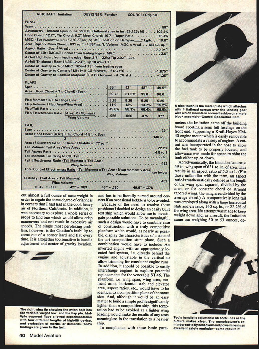
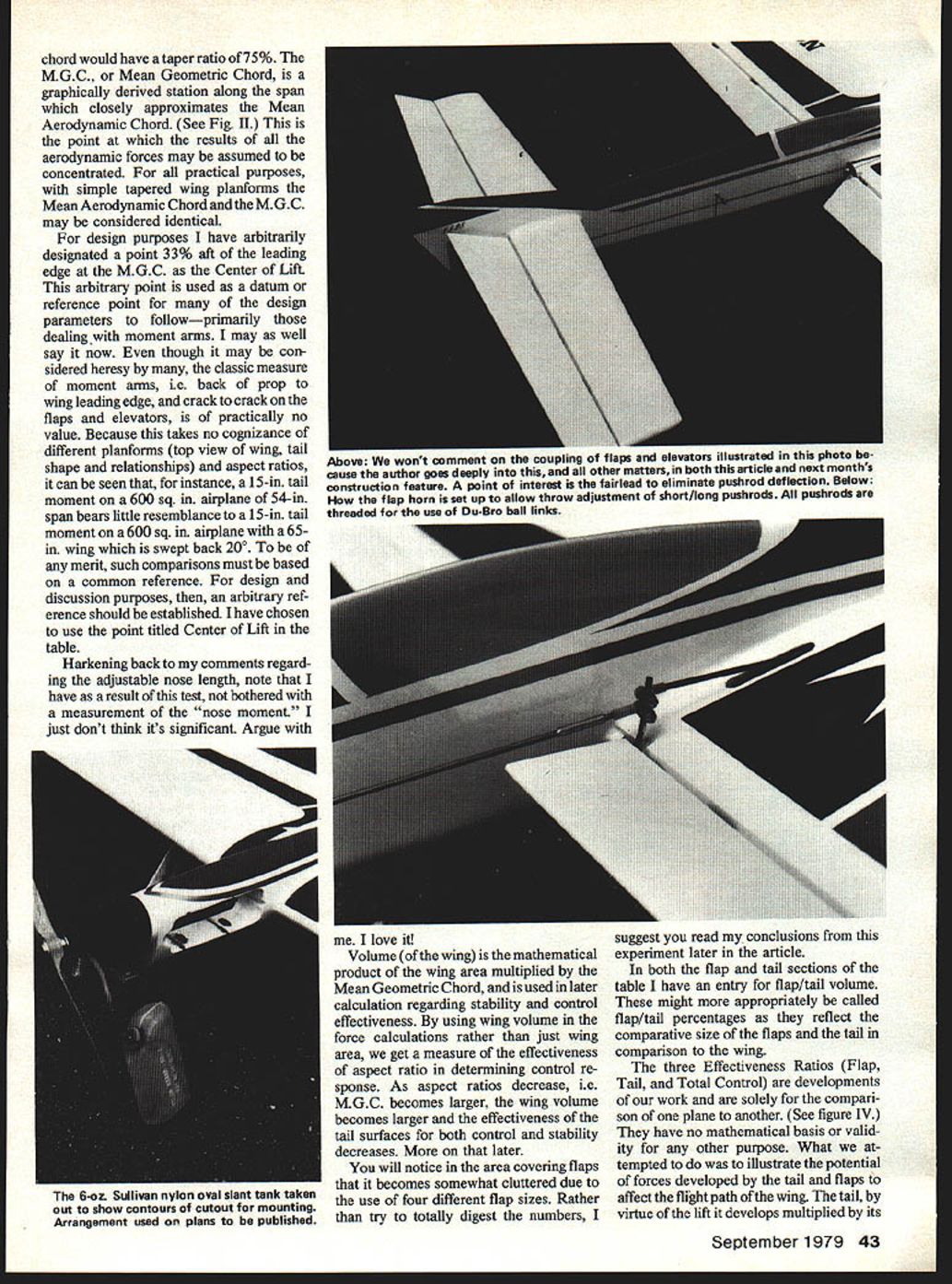
In compliance with these parameters the Imitation came off the building board with a semi full fuselage front end, supporting a Kraft-Hayes KM-40 engine mount which is easily removable to accommodate a variety of engines. A cutout was incorporated in the nose to allow the fuel tank to be properly located, and allowance was made for space to shim the tank either up or down.
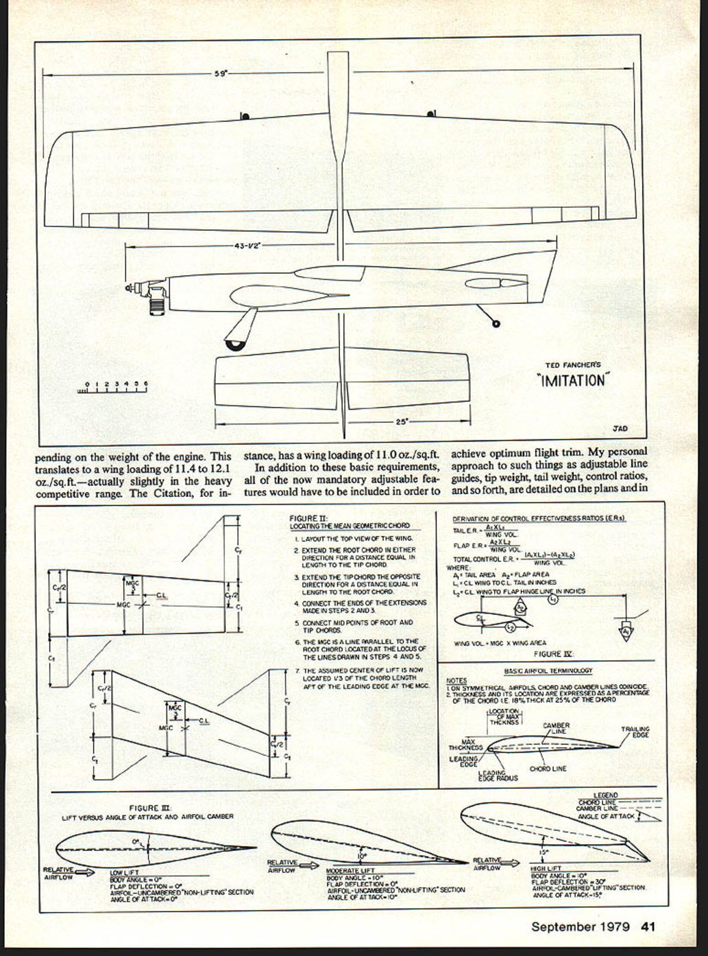
Aerodynamically, the Imitation features a 59-inch wingspan and 631 sq. in. of wing area, resulting in an aspect ratio of approximately 5.5:1. (Aspect ratio is wingspan squared divided by wing area; for constant-chord wings it's equivalent to span divided by chord.) A comparatively long tail was employed along with a large horizontal stab and elevator—140 sq. in., or 22.2% of the wing area. No attempt was made to keep weight down and, as a result, the Imitation came out weighing 50 to 53 ounces. Depending on the engine weight, this translates to a wing loading of 11.4 to 12.1 oz./sq.ft.—slightly in the heavy competitive range (the Citation has a wing loading of 11.0 oz./sq.ft.).
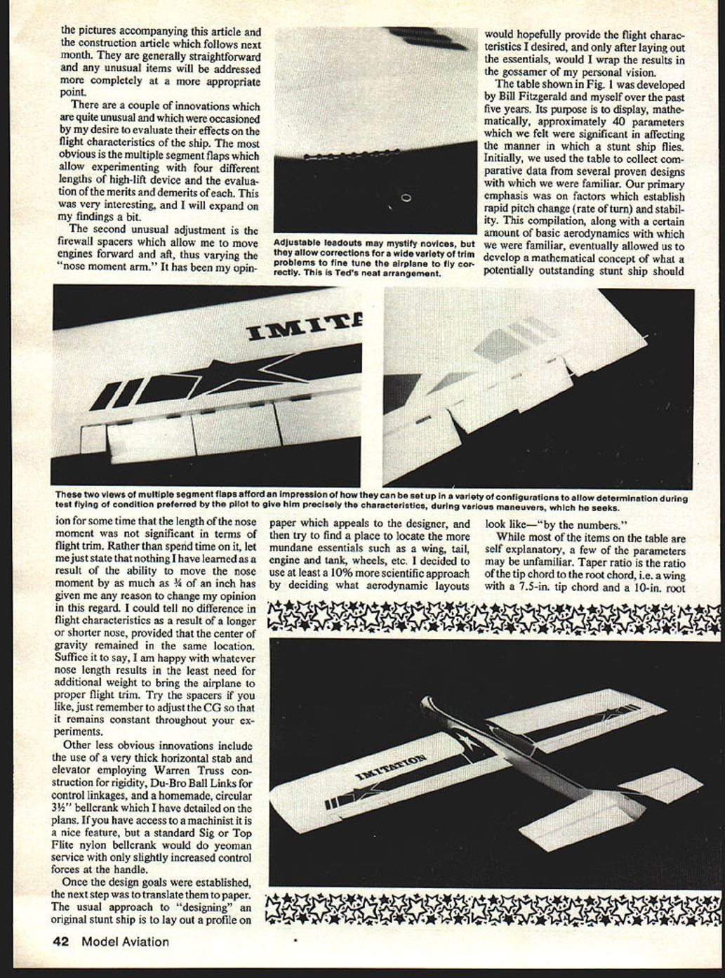
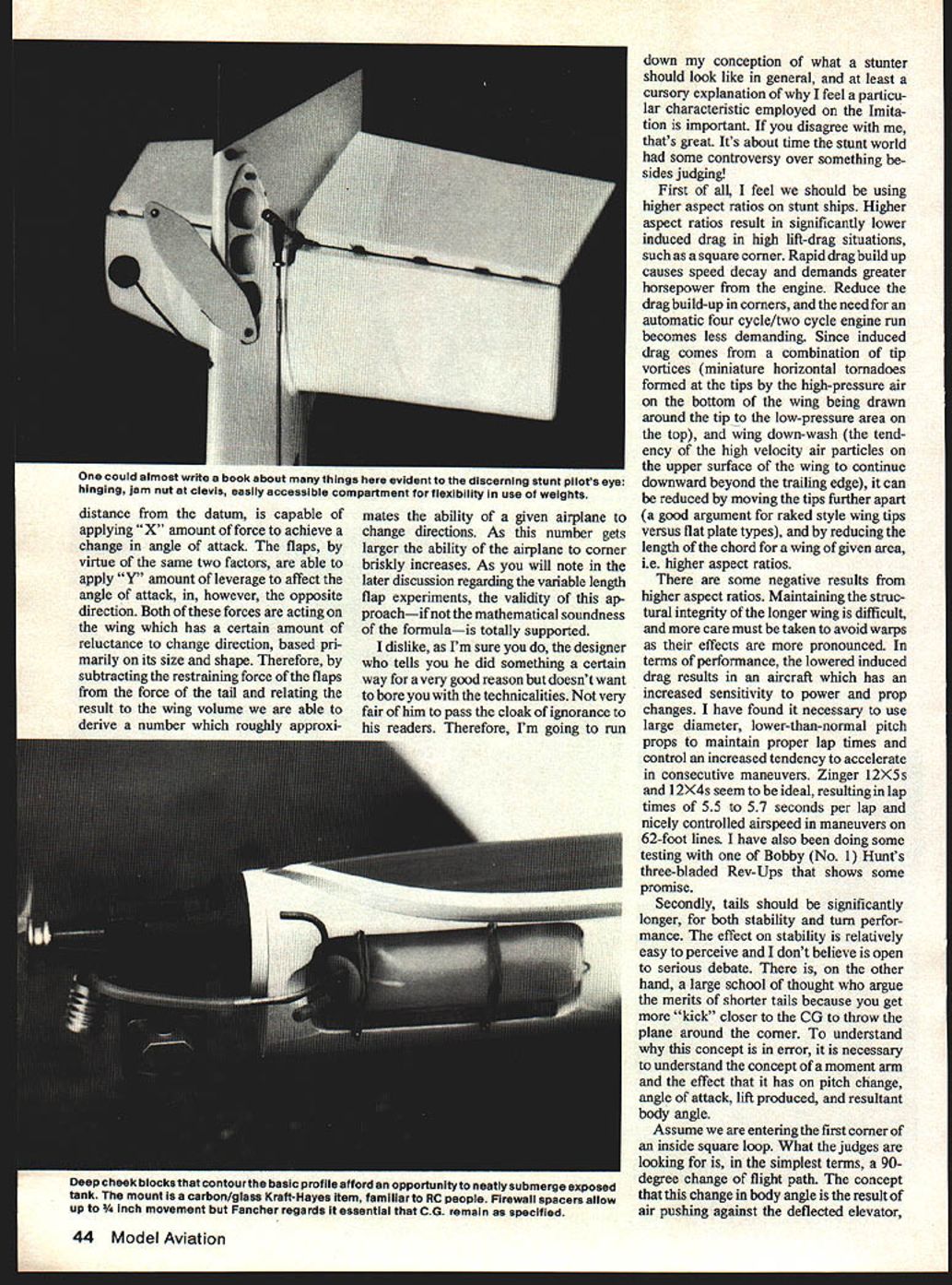
In addition to these basic requirements, all of the now-mandatory adjustable features were included to achieve optimum flight trim. My personal approaches to adjustable line guides, tip weight, tail weight, control ratios, and so forth are detailed on the plans and in the pictures accompanying this article and the construction article which follows next month. They are generally straightforward and any unusual items will be addressed at the appropriate point.
There are a couple of innovations that are quite unusual and were included to evaluate their effects on flight characteristics:
- Multiple-segment flaps allowing experimentation with four different lengths of high-lift device to evaluate merits and demerits of each.
- Firewall spacers allowing the engine to be moved forward and aft, varying the "nose moment arm." After testing, moving the nose moment by as much as 3/4" produced no perceptible difference in flight characteristics provided the center of gravity remained the same. The spacers are useful only insofar as they minimize the need for additional ballast to achieve the desired CG.
Other notable features include a very thick horizontal stab and elevator employing Warren truss construction for rigidity, DuBro ball links for control linkages, and a homemade 3-1/2" circular bellcrank detailed on the plans. A standard Sig or Top Flite nylon bellcrank will also do acceptable service with only slightly increased control forces at the handle.
Design process and analytical approach
Once the goals were established, the next step was to translate them to paper. Instead of starting with a profile and then squeezing in the essentials, I took a more scientific approach: decide what aerodynamic layouts would provide the desired flight characteristics, lay out the essentials, then wrap the results in the visual design.
The table shown in Fig. 1 was developed by Bill Fitzgerald and myself over five years. Its purpose is to display, mathematically, approximately 40 parameters we felt significant in affecting how a stunt ship flies. Initially we used the table to collect comparative data from several proven designs we were familiar with. Our emphasis was on factors that establish rapid pitch change (rate of turn) and stability. This compilation, with aerodynamic fundamentals, allowed us to develop a mathematical concept of what a potentially outstanding stunt ship should look like—"by the numbers."
Some parameters may be unfamiliar:
- Taper ratio: the ratio of tip chord to root chord. (A wing with a 7.5-in. tip chord and a 10-in. root chord has a taper ratio of 0.75.)
- M.G.C. (Mean Geometric Chord): a graphically derived station along the span that closely approximates the Mean Aerodynamic Chord (see Fig. II). For simple tapered wings, M.G.C. and Mean Aerodynamic Chord may be considered identical.
- Center of Lift: for design purposes I arbitrarily designate the point 33% aft of the leading edge at the M.G.C. as the Center of Lift. This is used as a datum for moment-arm-related parameters.
Classic measures of moment arms (e.g., back of prop to wing leading edge) are of little comparative value because they do not account for different planforms and aspect ratios. To be meaningful, comparisons must be based on a common reference—hence the use of the Center of Lift in our table.
Volume (of the wing) is wing area multiplied by the M.G.C. and is used in later calculations regarding stability and control effectiveness. Using wing volume rather than area incorporates the effect of aspect ratio on control response: as aspect ratio decreases (M.G.C. becomes larger), wing volume increases and tail effectiveness for control and stability decreases.
In the flap and tail sections of the table I use flap/tail percentages that reflect the comparative sizes of these surfaces relative to the wing.
The three Effectiveness Ratios (Flap, Tail, and Total Control) are developments of our work and are intended solely for comparing one plane to another (see Fig. IV). The idea is to illustrate the relative potential of forces developed by the tail and flaps to affect the wing's flight path. The tail produces lift multiplied by its distance from the datum (a torque producing pitch change one way); the flaps produce an opposing torque. Subtracting the restraining effect of the flaps from the tail force and relating the result to wing volume yields a rough number approximating an airplane's ability to change direction. As this number increases, cornering briskness increases. Flight tests with variable-length flaps validate the usefulness of this comparative approach.
Design philosophy and specific choices
I dislike designers who claim a feature is done "for good reason" without explaining why. Below are my conceptions of what a stunter should look like and why particular characteristics were used on the Imitation. Disagree if you like—controversy is healthy.
1. Higher aspect ratios
I believe we should be using higher aspect ratios on stunt ships. Higher aspect ratios reduce induced drag in high lift-drag situations (such as a square corner). Reduced induced drag lowers speed decay in corners and lessens the horsepower demand on the engine. Induced drag comes from tip vortices and wing downwash; it can be reduced by increasing span (moving the tips further apart) and by reducing chord length for a given wing area.
Downsides include structural challenges (longer wings are harder to keep warp-free) and increased sensitivity to power and prop changes. To control speed and lap times I have found larger-diameter, lower-pitch props ideal—examples include Zinger 12x5s and 12x4s, yielding lap times of 5.5 to 5.7 seconds on 62-foot lines. Three-bladed Rev-Ups show some promise too.
2. Longer tails
Tails should be significantly longer for stability and turn performance. Some argue for shorter tails to get more "kick" near the CG, but that misses the physics. The elevator does not directly "push" the plane around a corner: it changes the wing's angle of attack, and the wing's lift does the work. Increasing tail length increases elevator effectiveness (for a given elevator size), allowing faster changes in angle of attack with less control deflection. This yields smooth, rapid control response—valuable in contest flying.
3. Small fuselage
The fuselage should be as small as possible consistent with strength and fuel capacity. A smaller fuselage reduces frontal area and parasitic drag. Locating the fuel tank close to the CG reduces balance changes as fuel is consumed.
4. Low or inverted engine and stable fuel system
The engine should be mounted inverted, or at least low, and the fuel system arranged so the CG does not shift with throttle changes. On the Imitation the fuel tank is located just behind the engine so fuel weight changes do not greatly affect pitching moment.
5. Simple high-lift wing section (no reflex)
The wing should use a simple high-lift section with no reflex, as reflex tends to reduce lift at the high angles of attack needed in contest maneuvers. Some designers prefer reflex for static stability, but I have found that set-up changes are easier with conventional camber.
How the tail actually works (clearing up misconceptions)
It must be understood that the tail functions not by simply "deflecting air" to rotate the aircraft about the CG, but rather by producing lift like any lifting surface—through pressure differences above and below the airfoil. That lift multiplied by its distance from the aircraft's center of gravity produces a moment (torque). Increase the lift or the distance (moment arm) and the resulting pitching moment increases. That moment causes the aircraft to pitch, increasing the wing's angle of attack and hence its lift. Assuming enough thrust to overcome the induced drag associated with the added lift, the aircraft will continue to increase angle of attack while the tail force is applied, proportionally to that force, until it is removed and the plane continues on the new flight path.
Thus, longer tail moments result in tighter turns with less lift and drag than shorter tails, because the same change in wing angle of attack (and therefore flight path) can be achieved with less elevator deflection and less induced drag penalty.
Control forces and design responses
As aircraft size increases, control inputs necessary to deflect larger control surfaces against the slipstream become greater. For small pilots who perform hundreds of practice flights a year, the increased muscle demand in the handle becomes substantial. This can be attacked aerodynamically and mechanically.
Aerodynamically:
- Reduce the proportion of the surface which is deflected (i.e., smaller elevators and flaps).
- Keep the chord of deflected surfaces as short as reasonable. Long, narrow surfaces (high aspect ratio) require less control leverage than short, wide ones. A practical demonstration: deflect a rectangular board both lengthwise and widthwise out of a car window at 55 mph—lengthwise you feel much greater resistance.
- For flaps, limit deflected chord to between 15–20% of wing chord at a station. On the Imitation, flaps are 17% of the chord at all stations.
Mechanically:
- Increase mechanical advantage over aerodynamic resistance—achieve better bellcrank geometry, pushrod spacing, and horn lengths.
- Use ball links and smooth bellcrank bearings to reduce friction and slack.
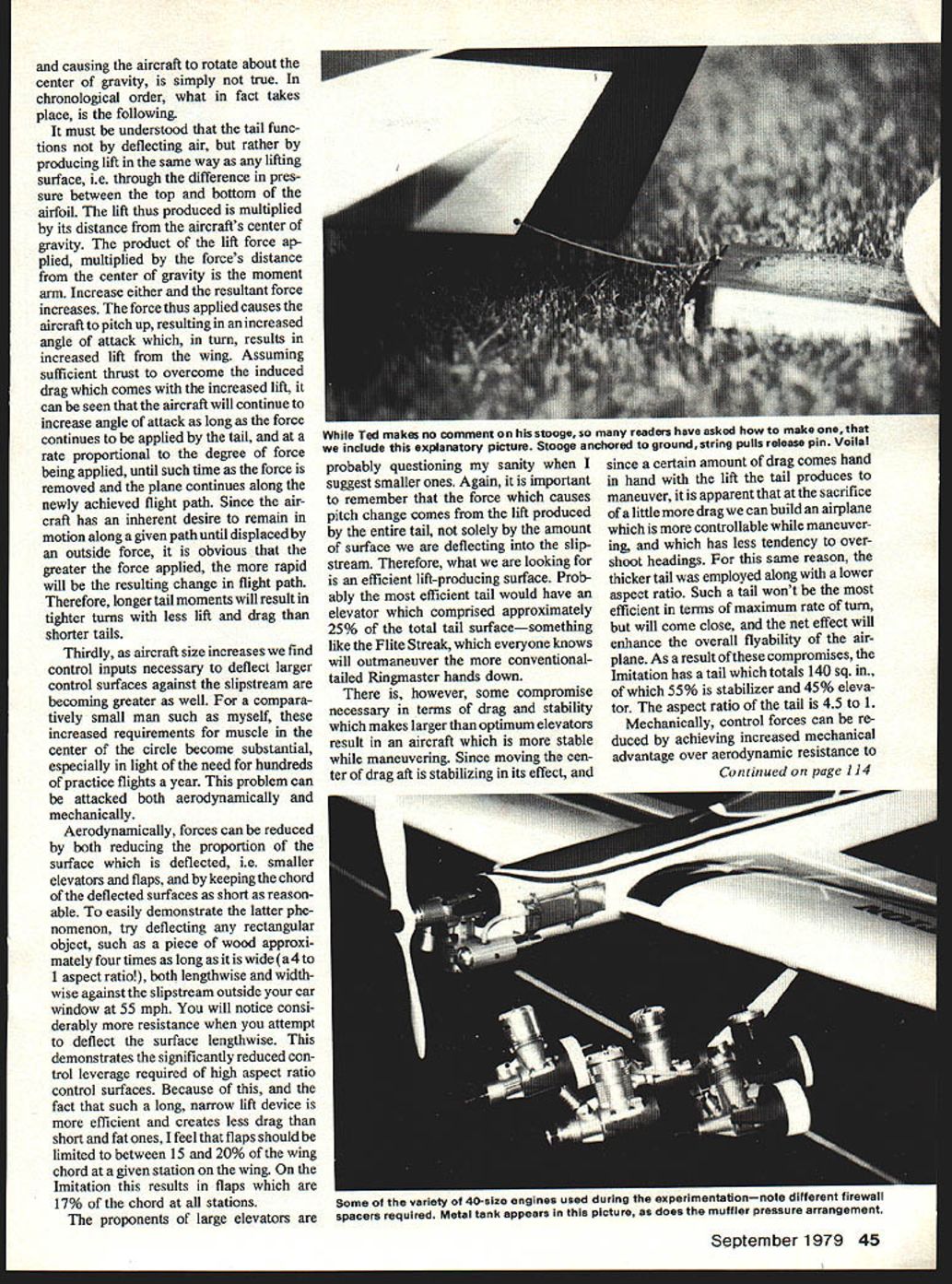
The proponents of large elevators may object to smaller elevators. Remember that the pitch change force comes from lift produced by the entire tail, not just the deflected surface. An efficient tail produces the needed moment; in practice, somewhat larger elevators can make the aircraft more stable while maneuvering at the expense of a little more drag. For this reason the Imitation uses a thicker, lower-aspect-ratio tail: total tail area is 140 sq. in., 55% stabilizer and 45% elevator, with a tail aspect ratio of 4.5:1. It is a compromise that yields excellent flyability and acceptable maximum rate of turn.
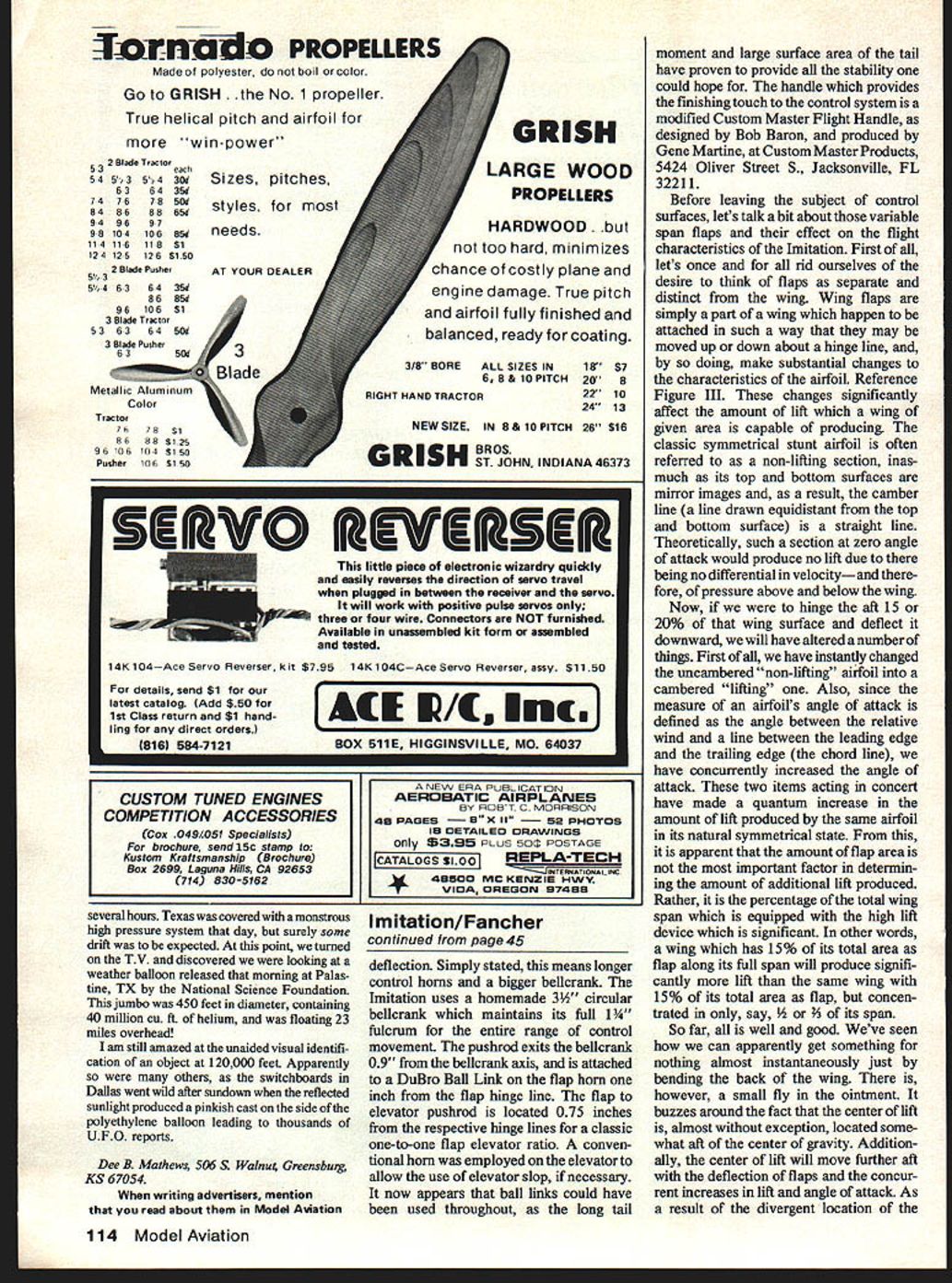
Mechanically, the Imitation uses a homemade 3/4" circular bellcrank with a full 1-3/4" fulcrum for the entire range of control movement. The pushrod exits the bellcrank 0.9" from the bellcrank axis and attaches to a DuBro ball link on the flap horn 1" from the flap hinge line. The flap-to-elevator pushrod is located 0.75" from the respective hinge lines for a classic one-to-one flap-elevator ratio. A conventional horn is used on the elevator to allow some elevator slop if necessary. In retrospect, ball links could have been used throughout, as the long tail moment and large tail area provide ample stability. The handle that caps the control system is a modified Custom Master Flight Handle (Bob Baron design), produced by Gene Martine at Custom Master Products, Jacksonville, FL.
Variable-span flaps: theory and experiment
First, let's rid ourselves of thinking of flaps as separate from the wing. Flaps are part of the wing that can be moved about a hinge line to change the airfoil camber and the chord line, producing large lift changes. Symmetrical stunt airfoils are often called "non-lifting," but deflecting the aft 15–20% instantly cambers the section and increases the angle of attack, producing a quantum increase in lift.
The key point: the percentage of total wing span equipped with high-lift device matters more than the absolute flap area at a single station. A wing with 15% of its total area as flap distributed along the full span produces significantly more lift than the same flap area concentrated over just part of the span.
There is a complication: the center of lift is normally aft of the center of gravity, and deflecting flaps moves the center of lift further aft, producing a nose-down pitching moment. The elevator must counter this pitching moment by producing an opposing moment (or incidence must be offset). This increases loads on control linkages and bellcranks.
Ways to minimize adverse pitching moment:
- Reduce flap size (undesirable because it reduces lift).
- Use higher aspect ratio wings (reduces distance between CL and CG).
- Use smaller-chord flaps (less rearward shift of CL with deflection).
- Move the CL forward (I placed the airfoil's high point at 22% chord full-span on the Imitation, 8% forward of the Citation's 30%).
- Move the CG aft (adding tailweight) if the design's stability allows it.
The Imitation's high stability coefficient—a large tail on a long arm—permits moving the CG aft without instability, improving the ability to come out of corners hard and flat compared to the Citation. Moving the CL forward and the ability to place the CG further aft while retaining stability are primarily responsible for the improvement.
There is a silver lining: the negative pitching moment from aft CL is stabilizing. It resists attitude changes and helps stop motion precisely, much like moderate brake pressure on a spinning wheel aids precise stopping.
Flight tests with varying flap spans confirm this reasoning. Initially the Imitation was flown with only the inboard flap sections operative (about 60% of span flapped and only 11% of wing area movable). In that configuration corners were spectacular—very tight—but round maneuvers suffered from a tendency to wander and visible flat spots in rounds from minor control inputs. As more span was flapped the extremes moderated: corners remained tight but became much more controllable and precise, and tracking improved in rounds. The large tail and long moment arm provided the leverage needed to overcome the adverse pitching moment and retain good turn potential even with full-span flaps.
The flap experiments were tempting to translate directly to competition designs (variable effective flap span to suit wind conditions), but I advise caution. Fixing some flap in windy weather to reduce pitching moment might help corners but can hurt round maneuvers and prevent intimate understanding of your aircraft. From my experiments I cautiously generalize that a little too much flap is probably better than too little, but I would not recommend adjustable-span flaps as a standard competition modification without more practice and familiarity.
Results and conclusions
These are the high points of the design philosophy that produced the Imitation. To call the plane a success is an understatement. It is in most respects the best flying plane I have flown; in terms of tight, precise corners it has few peers. All experimental features tested on the Imitation were so successful that their results are being incorporated into my new competition ship, the Excitation.
Because of its relative ease of construction the Imitation should be a reasonable project for any builder with a few profiles under his belt. Due to its outstanding flying capabilities it is a perfect selection as a contest machine for beginners and advanced fliers alike. Any builder who desires a far better-than-average plane for practice or Sunday barnstorming ought to take a close look.
(To be Continued)
Suggested Reading
- Fundamentals of Aircraft Flight — Frederick K. Teichmann, Hayden Book Co., Inc., Rochelle Park, N.J.
- Aerodynamics for Naval Aviators — Issued by the Office of the Chief of Naval Operations Aviation Training Division (Primarily Chapter 1, Pages 1–95).
FLY SAFELY!
Transcribed from original scans by AI. Minor OCR errors may remain.

