
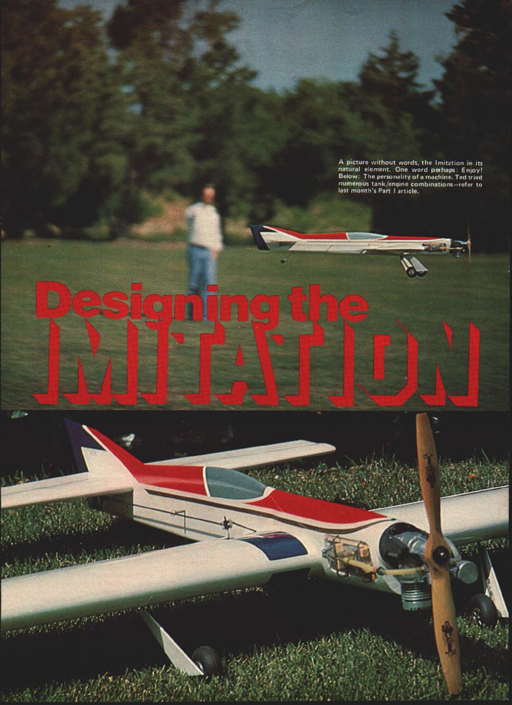
Designing the Imitation
Following last month's in-depth study, "Designing the Imitation," I am pleased to present a superior project — the best-ever stunt machine.
Ted Fancher
Editor's Note
Due to the overwhelming amount of material accompanying the project, the detailed pictures of the airplane presented in last month's installment were omitted; the reader is referred to the September issue.
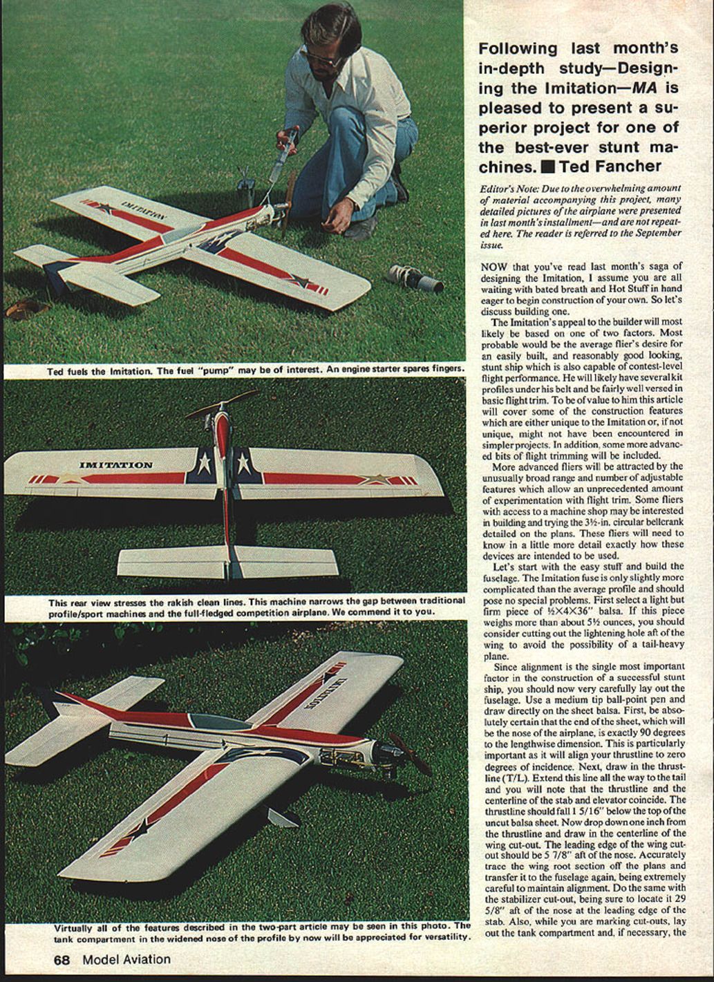
Now that you've read last month's saga, "Designing the Imitation," I assume you're waiting, bated breath and eager hands, to begin construction of your own. So let's discuss building.
The Imitation's appeal to the builder will likely be based on two factors. Most probable would be the average flier's desire for an easily built, reasonably good-looking stunt ship also capable of contest-level flight performance. He will likely have several kit profiles under his belt and be fairly well versed in basic flight-trimming procedures.
This article will cover some construction features either unique to the Imitation or which you might not have encountered in simpler projects. In addition, some advanced bits of flight trimming will be included. Advanced fliers will be attracted by an unusually broad range of adjustable features which allow an unprecedented amount of experimentation in flight trim. Some fliers with access to a machine shop may be interested in building the 3-inch circular bellcrank detailed on the plans; fliers will need to know little detail exactly how the devices are intended to be used.
Fuselage
Let's start with the easy stuff — building the fuselage. The Imitation fuselage is slightly more complicated than the average profile but should pose no special problems.
First select a light but firm piece of 1/4" x 4" x 36" balsa. If this piece weighs more than about 5-1/2 ounces, you should consider cutting out the lightening hole aft of the wing to avoid the possibility of a tail-heavy plane.
Since alignment is the single most important factor in the construction of a successful stunt ship, you should now very carefully lay out the fuselage. Use a medium-tip ball-point pen and draw directly on the sheet balsa.
- Be absolutely certain that the end of the sheet, which will be the nose of the airplane, is exactly 90 degrees to the lengthwise dimension. This is particularly important as it will align your thrustline to zero degrees of incidence.
- Draw in the thrustline (T/L) and extend this line all the way to the tail. The thrustline and the centerline of the stab and elevator should coincide. The thrustline should fall 1-5/16" below the top of the uncut balsa sheet.
- Drop down one inch from the thrustline and draw in the centerline of the wing cut-out. The leading edge of the wing cut-out should be 5-7/8" aft of the nose.
- Accurately trace the wing root section off the plans and transfer it to the fuselage, being extremely careful to maintain alignment.
- Do the same with the stabilizer cut-out, locating it 29-5/8" aft of the nose at the leading edge of the stab.
- While marking cut-outs, lay out the tank compartment and, if necessary, the lightening cut-out aft of the fuselage.
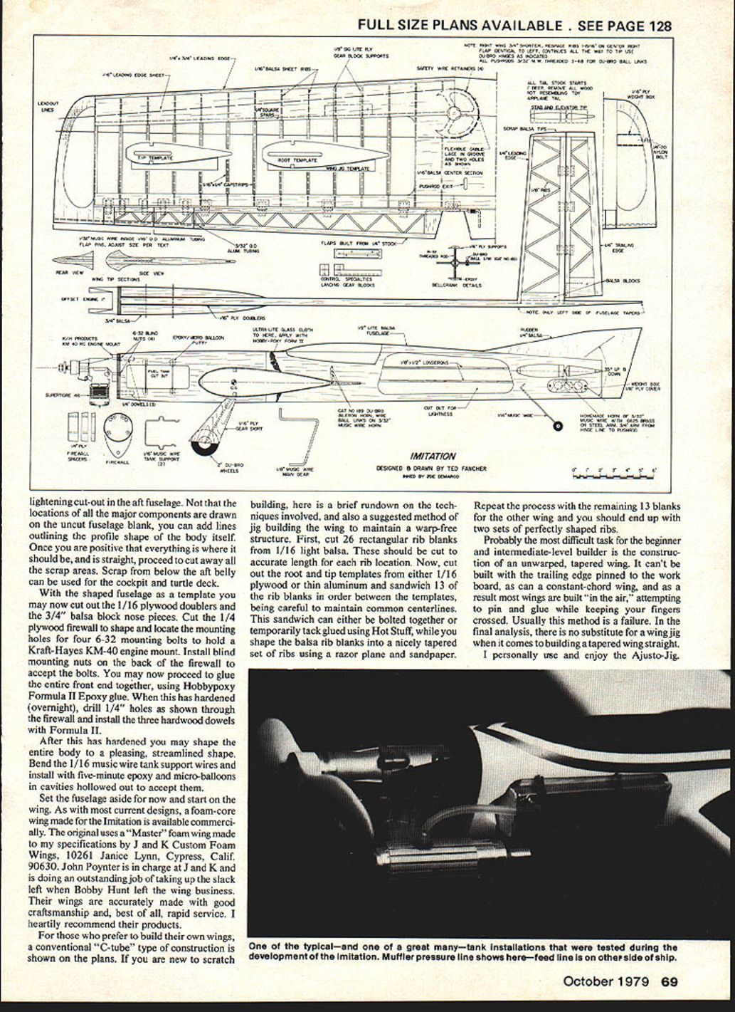
The locations of major components are drawn on the uncut fuselage blank; you can add lines outlining the profile shape of the body itself. Once you are positive everything is straight, proceed to cut away scrap areas. Scrap from below the aft belly can be used for cockpit and turtle-deck shaped fuselage templates.
With the shaped fuselage as a template you may now cut out the 1/16" plywood doublers and the 3/4" balsa block nose pieces. Cut the 1/4" plywood firewall to shape and locate the mounting holes for four 6-32 mounting bolts to hold a Kraft-Hayes KM-40 engine mount. Install blind mounting nuts on the back of the firewall to accept the bolts.
Glue the entire front end together using Hobbypoxy Formula II epoxy glue. When this has hardened (overnight), drill 1/4" holes as shown through the firewall and install the three hardwood dowels with Formula II.
After this has hardened you may shape the entire body to a pleasing, streamlined shape. Bend the 1/16" music wire tank support wires and install them with five-minute epoxy and micro-balloons in cavities hollowed out to accept them.
Set the fuselage aside for now and start on the wing.
Wing
As with most current designs, a foam-core wing made for the Imitation is available commercially. The original uses a "Master" foam wing made to my specifications by J and K Custom Foam Wings, 10261 Janice Lynn, Cypress, Calif. 90630. John Poynter is in charge at J and K and is doing an outstanding job of taking up the slack left when Bobby Hunt left the wing business. Their wings are accurately made with good craftsmanship and, best of all, rapid service. I heartily recommend their products.
For those who prefer to build their own wings, a conventional "C-tube" type of construction is shown on the plans. If you are new to scratch building, here is a brief rundown on the techniques involved, and also a suggested method of jig building the wing to maintain a warp-free structure.
Rib construction and templates
First, cut 26 rectangular rib blanks from 1/16" light balsa. These should be cut to accurate length for each rib location. Now, cut out the root and tip templates from either 1/16" plywood or thin aluminum and sandwich 13 of the rib blanks in order between the templates, being careful to maintain common centerlines. This sandwich can either be bolted together or temporarily tack glued using Hot Stuff while you shape the balsa rib blanks into a nicely tapered set of ribs using a razor plane and sandpaper.
Repeat the process with the remaining 13 blanks for the other wing and you should end up with two sets of perfectly shaped ribs.
Jig building and wing assembly
Probably the most difficult task for the beginner and intermediate-level builder is the construction of an unwarped, tapered wing. It can't be built with the trailing edge pinned to the work board, as can a constant-chord wing, and as a result most wings are built "in the air," attempting to pin and glue while keeping your fingers crossed. Usually this method is a failure. In the final analysis, there is no substitute for a wing jig when it comes to building a tapered wing straight.
I personally use and enjoy the Ajusto-Jig. However, not having access to a commercial jig should not discourage a builder, as there are a number of methods available to jig build a wing using ordinary materials. It might not be as convenient as some of the fancy ones but, if the wing comes out straight, it has done its job.
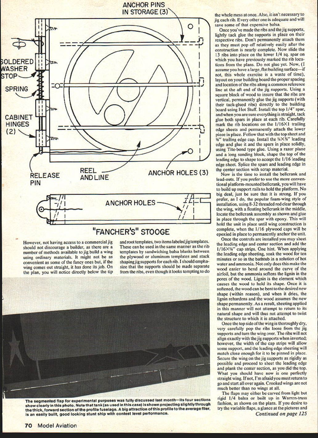
On the plan, you will notice directly below the tip and root templates, two items labeled jig templates. These can be used in the same manner as the rib templates by sandwiching balsa blanks between the plywood or aluminum templates and stack-shaping jig supports for each rib. I should emphasize that the supports should be made separate from the ribs, even though it looks tempting to do the whole mess at once. Also, it isn't necessary to jig each rib. Every other one is adequate and will save some of that expensive balsa.
Once you've made the ribs and the jig supports, lightly tack glue the supports in place on their respective ribs. Don't permanently attach them as they must pop off relatively easily after the construction is nearly complete. Now slide the 13 ribs into place on the lower 1/4" sq. spar on which you have previously marked the rib locations from the plans. Do not glue yet.
Assuming you have a large, flat building surface, lay out on your building board the proper spacing and location of the ribs along a common reference line at the aft end of the jig supports. Using a square block of wood to ensure that the ribs are vertical, permanently glue the jig supports (with their tack-glued ribs) directly to the building board using Hot Stuff. Install the top 1/4" spar, and when you are sure everything is straight, tack glue both spars in place at each rib.
Carefully mark the rib locations on the 1/16" x 1" trailing edge sheets and permanently attach the lower piece in place. Follow that with the top sheet and 3/8" trailing edge cap. Install the 1/4" x 3/4" leading edge and glue it and the spars in place solidly, using Tite-Bond type glue. Using a razor plane and a long sanding block, shape the top of the leading edge to accept the 1/16" leading edge sheet. Splice the spars and leading edge in the center section with scrap material.
Bellcrank and lead-outs
Now is the time to install the bellcrank and lead-outs. If you prefer to use the more conventional platform-mounted bellcrank, you will have to build up support rails to hold the platform. No big deal, just be sure that it is strong.
If you prefer, as I do, the popular foam-wing style of installation, use 8-32 threaded rod clear through the wing, with a floating bellcrank in the middle. Locate the bellcrank assembly as shown on the plans and glue in place through the spar with epoxy. This will hold the unit in place until wing construction is complete, when the 1/16" plywood caps will be epoxied in place to permanently anchor the unit.
Once the controls are installed you may sheet the leading edge and center section and add the 1/16" x 1/4" cap strips.
One hint: When applying the leading edge sheeting, soak the wood for ten minutes or so in the bathtub in a solution of hot water and ammonia. Not only does this make the wood easier to bend around the curve of the airfoil, but the ammonia softens the lignin in the pores of the wood. Lignin is the element which causes the wood to hold its shape. Once it is softened, the wood can be bent to the desired new shape (within reason), and when it dries the lignin reharden[s] and the wood assumes the new shape permanently. As a result, sheeting applied in this manner will not attempt to return to its natural shape and will thus not attempt to twist the structure to which it is attached.
Once the top side of the wing is thoroughly dry, very carefully pop the ribs loose from the jig supports and turn the wing over. The ribs will not align exactly with the jig supports when inverted; however, the width of the cap strips will allow some support, and the leading edge sheeting will match close enough for it to be pinned in place. Secure the wing on the jig supports as rigidly as possible and proceed to sheet the leading edge and plank the center section, as you did the top. What you should have now is one perfectly straight wing. If not, I'm afraid you must return to go and start all over again. Crooked wings are not much better than no wings at all.
Flaps, tips and gear
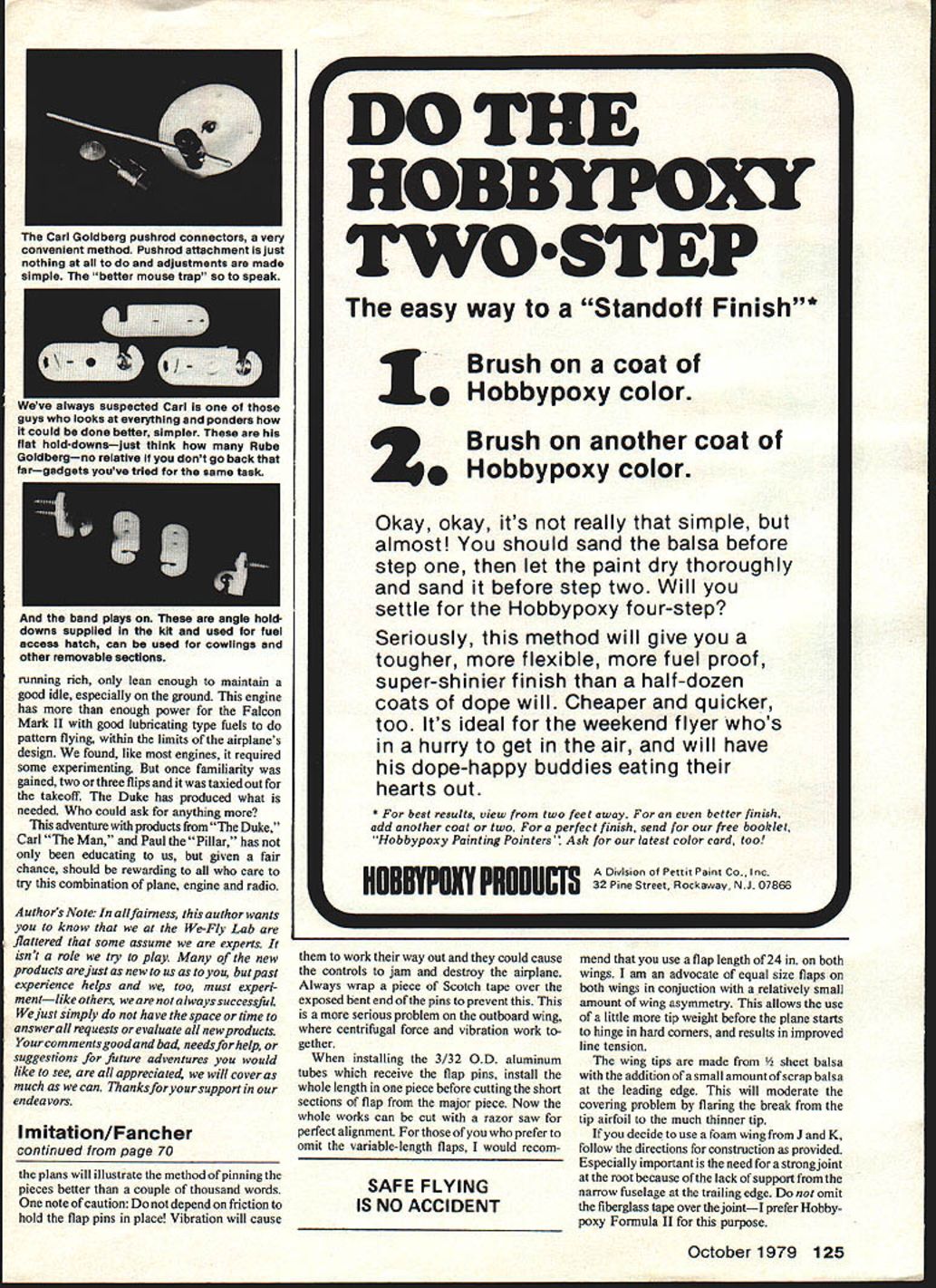
The flaps may either be carved from light but rigid 1/4" balsa or built up in Warren-truss fashion, as shown on the plans. If you desire to try the variable flaps, a glance at the pictures and the plans will illustrate the method of pinning the pieces better than a couple thousand words.
One note of caution: Do not depend on friction to hold the flap pins in place! Vibration will cause them to work their way out and they could cause the controls to jam and destroy the airplane. Always wrap a piece of Scotch tape over the exposed bent end of the pins to prevent this. This is a more serious problem on the outboard wing, where centrifugal force and vibration work together.
When installing the 3/32" O.D. aluminum tubes which receive the flap pins, install the whole length in one piece before cutting the short sections of flap from the major piece. Now the hole work can be cut with a razor saw for perfect alignment.
For those of you who prefer to do the variable-length flaps, I would recommend that you use a flap length of 24" on both wings. I am an advocate of equal size flaps on both wings in conjunction with a relatively small amount of wing asymmetry. This allows the use of a little more tip weight before the plane starts to hinge in hard corners, and results in improved line tension.
The wing tips are made from 1/8" sheet balsa with the addition of a small amount of scrap balsa at the leading edge. This will moderate the covering problem by flaring the break from the tip airfoil to the much thinner tip.
If you decide to use a foam wing from J and K, follow the directions for construction as provided. Especially important is the need for a strong joint at the root because of the lack of support from the narrow fuselage at the trailing edge. Do not omit the fiberglass tape over the joint — I prefer Hobbypoxy Formula II for this purpose.
Whichever wing you choose to install, I recommend the use of the Control Specialties Co. landing gear blocks as shown on the plans. As you can see in the pictures, these are a very professional looking item with recessed tin plates held in place by countersunk screws. (These are also available from J and K Wings.) Installation instructions are provided with the foam wing.
If you are building up the wing, make up rib doublers from 1/8" Sig-lite ply for the ribs shown supporting the gear blocks. Then, merely notch the ribs to match the gear mounts and epoxy the mount to the two ribs and the spar. This type of mount is very strong and I recommend it highly.
The multiple-hole adjustable lead-out guide was copied exactly from some guy's red Nobler that keeps showing up at the Nats year after year. It's very simple and lighter than fixed lead-outs by maybe two grams. However, if you don't have the tools to drill the holes accurately and cleanly, you would be well advised to use one of the mechanical bolt and sliding block arrangements seen on many stunt ships. Sloppy holes in this system could cost an airplane!
The adjustable tip-weight box is one of my pet ideas. It is a simple plywood box with a No. 7 hole drilled and tapped through the balsa tip with a 4-40 thread to accept a nylon wing hold-down bolt. The head is cut off the bolt so that it will thread into the tip unobtrusively, and weight is added or subtracted in the form of lead shotgun pellets. Works great!
Tail
The tail on the original Imitation was built as shown on the plans and is a full one-inch thick at the root, tapering to 1/2" at the tips. It was built up on a flat building board using full one-inch-deep stock for all components: leading edge, trailing edge, hinge-line spars and ribs. All the components were Hot Stuffed directly to the building board and the top was then shaped with a razor plane and a long sanding block.
After the top was shaped, one-inch squares of scrap 1/4" balsa were Hot Stuffed temporarily to a dozen or so spots around the perimeter of the surface. The tail was then popped loose from the building board and remounted upside down, supported by the one-inch squares of scrap, again Hot Stuffing in place on the building board. The bottom of the tail was then shaped to match the top, resulting in a perfectly straight tapered tail section which is very rigid and weighs less than one ounce for the whole 140-sq. in. tail.
The tail could be made from a 1/4" very light balsa sheet, with very little deterioration in overall performance and considerably less work.
Controls
The control system on the original Imitation was built up almost entirely from scratch. The heart of the system is the 3-1/2" circular bellcrank, which is coupled to the homemade 3/32" music wire horns by a 3/32" pushrod. The pushrods are attached to the horns with Du-Bro ball links. These are very strong and nearly trouble-free. The only problem I have had with them is the 2-56 threaded rod pulling out of the nylon link.
To prevent this, I merely thread the pushrod with a 3-48 die and thread the ball-link directly to the rod. To avoid destroying your 3-48 die on the music wire, be sure to soften the area to be threaded by heating it in a torch until it is cherry red and then allowing it to air dry. It will be very hard but soft enough to thread.
The flap horn is made by bending 3/32" music wire as shown and silver soldering the two pieces together, after binding with copper wire. The elevator horn is the more conventional type with a flat steel arm, silver-soldered to the music wire. This was used to allow for the possibility of needing slop in the elevator for level flight stability. However, the Imitation has always been rock solid and has never required any slop to be used.
As with the thick tail, the homemade controls are a fine tuning refinement and could be replaced with conventional store-bought items with only minor deterioration in performance. If you are a serious stunt flier, however, I recommend you give this type of system a try, as it results in much lighter control forces. With the ball links to make alignment less critical, controls can be totally free from binds with almost no effort. The larger-than-normal arms on the horns and bellcrank, plus the circular shape which retains the full 1-1/4" lever arm on the lead-outs for the full range of control movement, gives a feeling similar to power steering. They are not sensitive but require very little effort to achieve any amount of control desired.
Final assembly and finishing
Once all your components are built, put them all together in the conventional manner—wings in front and the tail in back. If you make your cut-outs accurately, this is the only way they'll fit. Be absolutely sure that the wing and stab are squarely aligned with no decalage (i.e., incidence in either).
Start the finishing procedure by fine sanding everything in sight until the wood structure is flawless. Minor dents can be filled with Dap Vinyl Spackling Compound. Any major flaws should be filled with balsa for weight saving.
When satisfied with the condition of the surface, MonoKote the wing and tail. Gary McClellan had a very good rundown on the proper method of applying the heat-shrink covering some months back in Wynn Paul's column on stunt.
Begin finish of the fuselage by applying lightweight fiberglass cloth to the nose section with Hobbypoxy Formula II. When cured, sand the glass smooth and apply two coats of unthinned clear dope to the entire fuselage. Cover the fuse with light-weight Silkspan, using very thin dope as an adhesive. This is followed with one or two coats of full-strength clear.
Now apply the fillets using Sig Epoxolite. Be sure that your fillets overlap the edges of the MonoKote on all surfaces, as this will help make the covering bullet-proof as far as lifting is concerned.
If you haven't already done so, mask off all the MonoKote areas as the rest of the finish should be sprayed on. First, mix one tablespoon of talcum powder into a pint of clear dope. This is to thin the spray consistency. Apply one coat to the fuselage and rudder. Sand very carefully and you shouldn't have to use a second coat.
Once you are satisfied with the condition of the surface, mix up some Super Poxy color and spray on a very light tack coat. Allow this to set for about five minutes and proceed to spray on one wet coat. This should be all the color required. Remove the masking tape immediately before the paint sets up and it will leave almost no discernible edge. The original trim used Trim-Kote on the wing and Super Poxy colors on the fuselage. The gold stripe is D.J.'s striping tape.
Now, bolt on the motor, install the Pylon Brand S.O.6 slant oval tank shimmed with balsa to align with the spray bar, bolt on the wheels, and let's go flying!
Flying and trimming
The center of gravity shown on the plans was taken directly from the original after it had been well trimmed. It may be a good idea to start out with it slightly further forward on your first flights. The first flights should be confined to determining if the wing is straight, the tip weight approximately correct, and the tank located properly for both upright and inverted flight, and to get a feel for the way the plane reacts.
Have your helper watch the wings carefully, both in level flight and on end during maneuvers. If the wings do anything besides line up perfectly with the flying lines at all times, an adjustment is necessary in either tip weight or by straightening a warped wing.
A general statement can be made regarding which of the foregoing is the culprit in a given case:
- If the outboard wing is high upright and low inverted, it's a sure bet you have a warp problem.
- If the outboard wing is low (or high) both upright and inverted, you should be looking at the tip weight when you get it back on the ground.
- If it's low both ways, remove weight a quarter ounce at a time until they level out, and vice versa if the wing is high both ways.
Adjustable lead-outs are often a mystery to novices. Here are some symptoms of incorrect lead-out location to watch for:
- If the plane pulls hard in level flight but is loose at the top (the first loop of the clover, for instance), it indicates that the lead-outs are too far aft.
- If the airplane hangs in hard corners but flies with the wings level, you may have to move them forward.
- If the lead-outs get too far forward, the airplane would become too light on the lines and tend to nose in at you slightly each time you gave a sharp control input.
Contrary to popular thinking, more lead-out problems come from being too far aft than too far forward. Remember that a straight airplane wants to fly at a tangent to the circle and doesn't require large amounts of engine, line, or rudder offset to maintain adequate line tension. Keep in mind that less is generally best when dealing with trim adjustments.
The most efficient set-up will have the airplane flying as cleanly as possible, as opposed to crabbing sideways which creates unnecessary drag and robs thrust. A good clue to how cleanly your plane is flying is to examine the oil pattern on the bottom of the wing after a flight. The oil should have only a slight tendency to creep out the outboard wing and should continue the length of the fuselage. The lead-outs as shown on the plan should be within a fraction of an inch of correct for your plane.
The Imitation is not sensitive to trim changes, so feel free to experiment with a variety of trim adjustments. Try different flap/elevator ratios, different lead-out locations, move the C.G. around. It's amazing how much you can learn about trim if you take the time to experiment.
Engines
You have probably noticed that I have studiously avoided referring to my experiment with the .40-size engines, which was one of the prime reasons for developing the Imitation in the first place. While I flew the Imitation with a variety of motors, I'm afraid the only one to which I am prepared to give total endorsement is the good old S.T. .46.
I quickly found that none of the other engines, just straight out of the box, was going to give the kind of consistency and performance necessary for top-level stunt competition. But that's another story for another day.
Closing and contacts
Just one advertisement. If you like to fly stunt and you don't belong to PAMPA, the Stunt Pilot Fraternity, you're missing half the fun. Drop a line to Wynn Paul, our secretary/treasurer, at:
1640 Maywick Drive Lexington, KY 40504
If you want to discuss the Imitation, or stunt in general, drop me a line at:
158 Flying Cloud Isle Foster City, CA 94404
Transcribed from original scans by AI. Minor OCR errors may remain.

