
DH 98 Mosquito
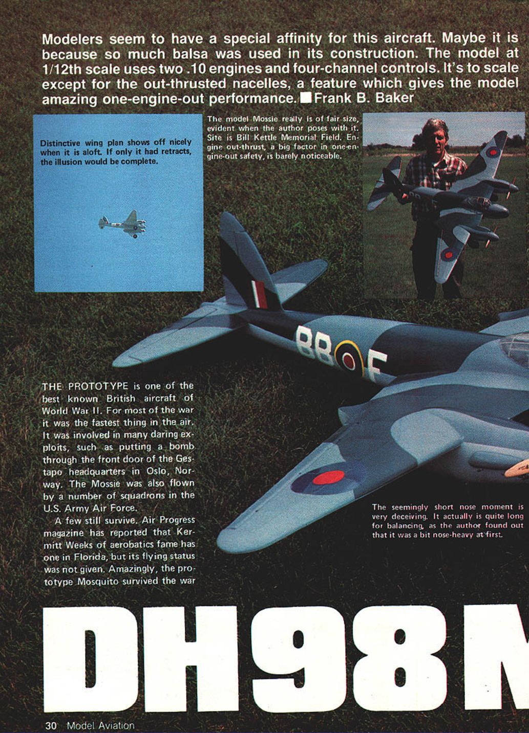
Modelers seem to have a special affinity for this aircraft — perhaps because so much balsa was used in its construction. The 1/12-scale model uses two .10 engines and four-channel controls. It's to scale except for the out-thrusted nacelles, a feature that gives the model amazing one-engine-out performance. — Frank B. Baker
The prototype Mosquito is one of the best-known British aircraft of World War II. For most of the war it was among the fastest aircraft in the air and was involved in many daring exploits, such as putting a bomb through the front door of the Gestapo headquarters in Oslo, Norway. The Mossie was also flown by a number of squadrons in the U.S. Army Air Force.
A few full-size Mosquitos still survive. Air Progress magazine has reported that Kermit Weeks has one in Florida (flying status not given). Amazingly, the prototype Mosquito escaped the scrap furnace and is on display at Salisbury Hall in England, where it was built.
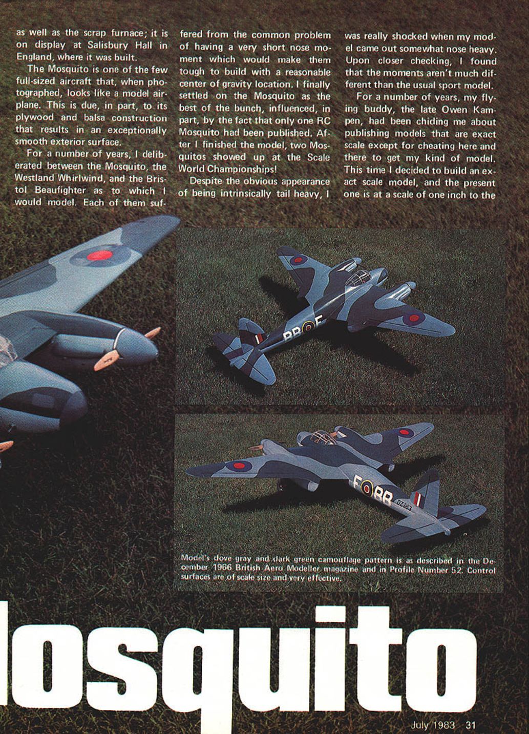
The Mosquito is one of the few full-sized aircraft that, when photographed, looks like a model airplane. This is due, in part, to its plywood-and-balsa construction, which results in an exceptionally smooth exterior surface.
For a number of years I debated between modeling the Mosquito, the Westland Whirlwind, and the Bristol Beaufighter. Each had the common problem of a very short nose moment, which would make them tough to build with a reasonable center of gravity. I finally settled on the Mosquito as the best of the bunch, influenced in part by the fact that only one RC Mosquito had previously been published. After I finished the model, two Mosquitos showed up at the Scale World Championships!
Despite the apparent tendency to be tail heavy, my model actually came out somewhat nose heavy. Upon checking, I found that the moments aren't much different than the usual sport model.
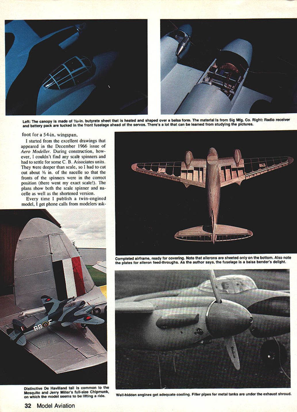
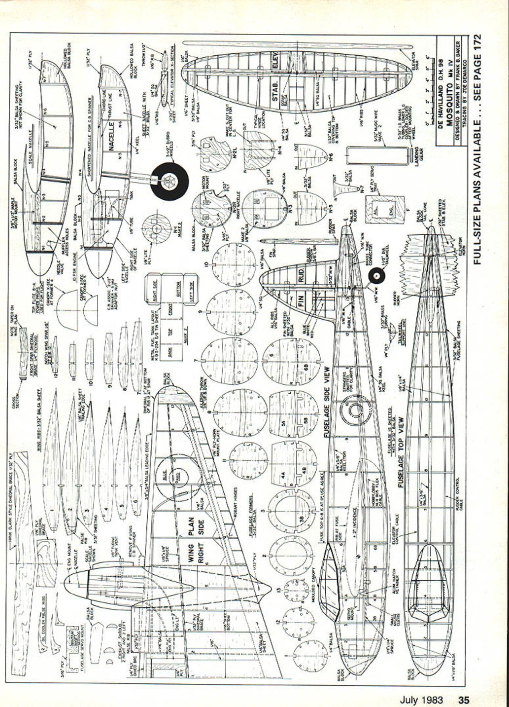
I decided to build an exact-scale model at a scale of one inch to the foot (1/12). The model has a 54-inch wingspan. I started from the excellent drawings that appeared in the December 1966 issue of Aero Modeller. During construction I couldn't find any scale spinners and had to settle for some C. B. Associates units. They were deeper than scale, so I cut away about 3/8 inch of the nacelle front so the spinner fronts sat in the correct position (there went my exact scale!). The plans show both the scale spinner and nacelle as well as the shortened version.
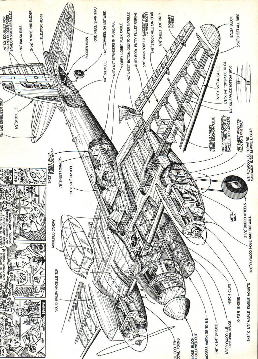
Every time I publish a twin-engined model I get phone calls about using bigger engines. There is a balance between overall size, wing area, weight and engine displacement; if I wanted larger engines I would have designed the model differently. Callers never seem convinced. I wanted a docile sport model, and I designed this example to be gentle in handling. Depending on the account, Baker mentions using different OS Max engines in various builds; the 1/12-scale model can be flown with .10 engines, and other versions have been built with .15–.19 displacement engines. In the example described here he installed OS Max .10FSR engines and achieved a flying weight of about 4 pounds.
Construction
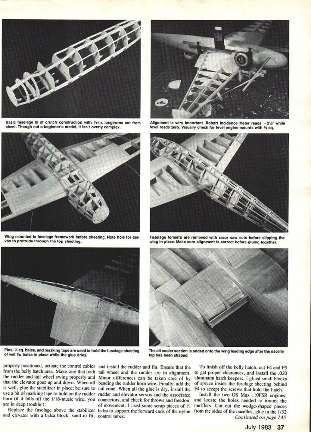
While not impossible, the Mosquito must be built in the proper order. The following highlights the major steps and important sequence points.
Wing
- Begin construction with the wing. Construction is conventional.
- Build the basic panels and install nylon tubing for the motor-control runs (Sullivan 507, GRC-3) and for the aileron runs (Hobby Lobby HLH-805). Be sure to bring the motor-control tubes out through the bottom wing at the leading edge. Note: the right control tube runs inside the nacelle; the left runs outside.
- Butt-glue the wing panels together with the proper dihedral (2 in. at Rib 12 of each wing). Use a razor saw to cut a 1/32-in. slot through Ribs 1–5 behind the spruce spars. Put plenty of glue in the slots and slip in a 1/32-in. plywood dihedral brace. Be careful not to break the ribs when bending.
- When dry, soak a 1/16-in. plywood dihedral brace in water, crease the centerline in a vise to the proper bend, and glue it in place. The result will be a strong, lightweight dihedral brace.
- Install the plywood servo mount and put connectors on the control cables. Slip the cables into the nylon tubes and mount the engine and aileron servos. Check that controls are free with easy motion.
- Once controls work smoothly, sheet top and bottom of the wing. Pay attention to the plans: there is a small 1/16-in. sheet on the top wings and 3/32-in. sheet forward of the spars.
- Set the completed wing aside.
Fuselage
- Build the 1/4-in. balsa keels. The top keel changes direction frequently; make it by gluing sections together to form the complete top keel. The bottom keel is cut from 1/4-in. sheet for F1–F8, and a piece of 1/4-in. square is spliced on at F8. Use a similar approach for the 1/8 x 1/4-in. side keels.
- Make all fuselage formers. Use a saw to almost cut out the wing slots in formers F5a–F8, leaving enough material so the formers hold together.
- Assemble the formers on the top keel. When the glue is dry, install the side and bottom keels and the top two stringers.
- Once the basic fuselage is together, cut out the wing slots and slip the wing into place. Use the top fuselage F6–F8 zero-degree reference line to set the wing at +2°.
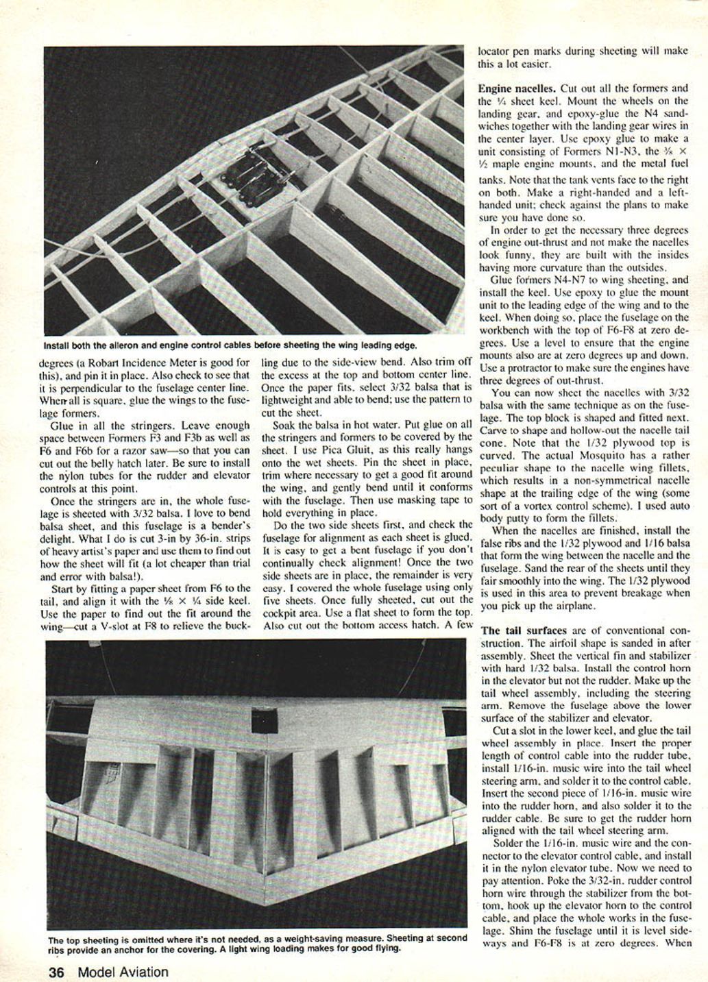
- Install rudder and elevator cables before sheeting the fuselage. Locator-pen marks during sheeting will make alignment easier.
- The plans show an enlarged hatch to improve access to the two rear servos.
Engine nacelles
- Cut out all nacelle formers and the 1/4-in. keel for the nacelle units.
- Mount the wheels on the landing gear and epoxy-glue the N4 sandwiches together with the landing-gear wires in the center layer.
- Epoxy the unit consisting of formers N1–N3, the 3/8 x 1/2-in. maple engine mounts, and the metal fuel tanks. Note: the tank vents face to the right on both units. Make a right-handed and a left-handed unit and check against the plans.
- To obtain the necessary three degrees of engine out-thrust without making the nacelles look odd, the nacelles are built with the inside surface more curved than the outside.
- Glue formers N4–N7 to the wing sheeting and install the keel. Use epoxy to glue the mount unit to the wing leading edge and to the keel.
- When positioning the mounts, place the fuselage on the workbench with the top of F6–F8 at zero degrees. Use a level to ensure the engine mounts are zero degrees up-and-down and a protractor to set three degrees of out-thrust.
- Sheet the nacelles with 3/32-in. balsa using the same technique as for the fuselage. Fit and shape the top block, carve and hollow the nacelle tail cone. Note that the 1/32-in. plywood top is curved.
- The full-size Mosquito nacelle wing fillets have unusual contours; the trailing edge nacelle shape is non-symmetrical. Use auto-body putty if needed to form the fillets for smooth airflow.
- Install the false ribs and the 1/32-in. plywood and 1/16-in. balsa that form the wing between the nacelle and the fuselage. Sand until the joints fair smoothly into the wing. The 1/32-in. plywood in this area helps prevent damage when picking up the airplane.
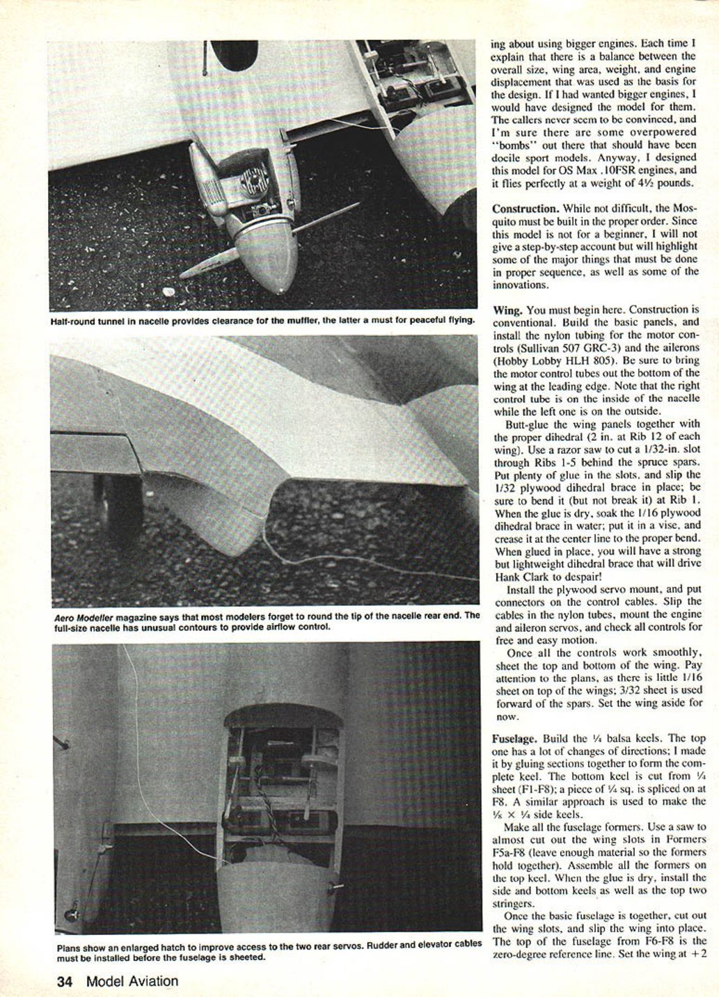
- Cut the wedge-shaped pieces from the sides of the nacelles where mufflers fit, glue in 1/32-in. plywood half-rounds, and sand flush. Mount the mufflers with 1/16–3/16-in. clearance. Trim exhaust shrouds to clear mufflers on the left and tank vents on the right. Finish throttle linkages and check motion.
Tail surfaces
- Tail surfaces are of conventional construction. Sand the airfoil shape in after assembly. Sheet the vertical fin and stabilizer with hard 1/32-in. balsa.
- Install the control horn in the elevator but initially not in the rudder.
- Make the tail wheel assembly including the steering arm. Remove the fuselage above the lower surface of the stabilizer and elevator as required.
- Cut a slot in the lower keel and glue the tail wheel assembly in place. Insert the proper length of control cable into the rudder tube, fit 1/16-in. music wire into the tail wheel steering arm and solder it to the control cable. Insert the second piece of 1/16-in. music wire into the rudder horn and solder it to the rudder cable. Align the rudder horn and tail wheel steering arm carefully.
- Solder the 1/16-in. music wire and connector to the elevator control cable and install it in the nylon elevator tube.
- Poke the 3/32-in. rudder control-horn wire through the stabilizer from the bottom, hook up the elevator horn to the control cable, and place the assembly in the fuselage. Shim until the fuselage is level sideways and F6–F8 is at zero degrees. When all is aligned, glue the stabilizer in place, using masking tape to hold the rudder horn if needed.
- Replace the fuselage sheeting above the stabilizer with a balsa block, sand to fit, position properly, actuate the control cables and install the rudder and fin. Ensure tail wheel and rudder alignment; small differences can be corrected by bending the rudder horn wire.
- Add the tail cone. When glue is dry, install the rudder and elevator servos and their connectors; check for adequate throws and freedom of movement.
- Use scrap pieces of 1/4-in. balsa to support the forward ends of the nylon control tubes if required.
- To finish the belly hatch, cut F4 and F5 for proper clearance and install .020-in. aluminum hatch keepers. Glue small spruce blocks inside the fuselage sheeting behind F4 to accept hatch screws.
Finishing
- The difficulty with scale models is matching camouflage colors with Mylar coverings. The author considered an RAF vice-marshal’s medium-blue, hand-rubbed finish but chose a more conventional scheme.
- The airframe received several coats of clear dope; sheeted areas received multiple coats of Aerogloss Balsa Fillercoat with sanding between coats until smooth.
- The complete model was covered with silk and brushed with clear Aerogloss until pores were filled. After base finishing, glue on exhaust shrouds.
- Spray two coats of aluminum Aerogloss with light sanding between coats.
- Spray the whole airplane one coat of Cessna gray. Mask dark areas and apply one coat of Stinson green darkened with flat black. Lighten the lower surfaces with Cessna gray mixed with white for contrast between upper and lower grays.
- Make a cockpit canopy by carving a balsa plug and molding Sig butyrate sheet material (softens at about 220°F). Be cautious with gluing the canopy to the fuselage: some instant glues can fog the inside; avoid glues that prevent future access.
- Use Williams Bros. 1-in.-scale pilots — the copilot sits slightly behind the pilot.
Flying
- Use propellers that get enough blade outside the spinner. The author used Top Flight 8x4 wooden Power Props; the OS Max .10s can turn them at reasonable RPM.
- This is a scale model and must be flown with respect. On takeoff the tail will lift quickly; do not leave the ground until you have built up adequate speed. Use just enough elevator to lift off and climb at a modest angle.
- The Mosquito is quite fast once airborne. The narrow, pointed wingtips make it sensitive to ailerons, especially at higher speeds. Experiment with throws until ailerons are effective without being abrupt.
- Landings: set up a long, flat approach and control descent with throttle. Keep it flying level until the wheels touch, then idle the engines.
- Single-engine performance is outstanding; the author has lost an engine and not realized it until final approach, when he noticed the stopped propeller.
- A final caution: the gray camouflage can make orientation difficult at distance. Keep the model in close, as it’s prettier and easier to control up close.
- Overall, the Mosquito is a very smooth-flying, scale-like model. Installing retractable gear would be a spectacular sight in the air.
Transcribed from original scans by AI. Minor OCR errors may remain.

