
Digital Programme
If you've ever lost a plane due to a battery that was either undercharged or "cooked" to death from too much charging, then this is one article you won't want to miss.
Eloy Marez
As our RC equipment has become increasingly sophisticated, so have the power requirements. We are seeing a growing variety of nickel-cadmium batteries available for our use, and with them increasingly varied charging requirements in rates and times.
The basics don't change. You can't afford to undercharge and risk running out of battery power while in flight. Neither can you afford to overcharge; a small amount of overcharge will assure you've reached 100% charge, but consistent overcharging will eventually result in cell gassing, loss of capacity, shortened battery life, and (in worst cases) the loss of an airplane. Therefore, it is important to follow the manufacturer's recommendations on charging times — which adds another schedule to an already busy life. We have to remember to start charging at a certain time and to end it before we are fast asleep or away.
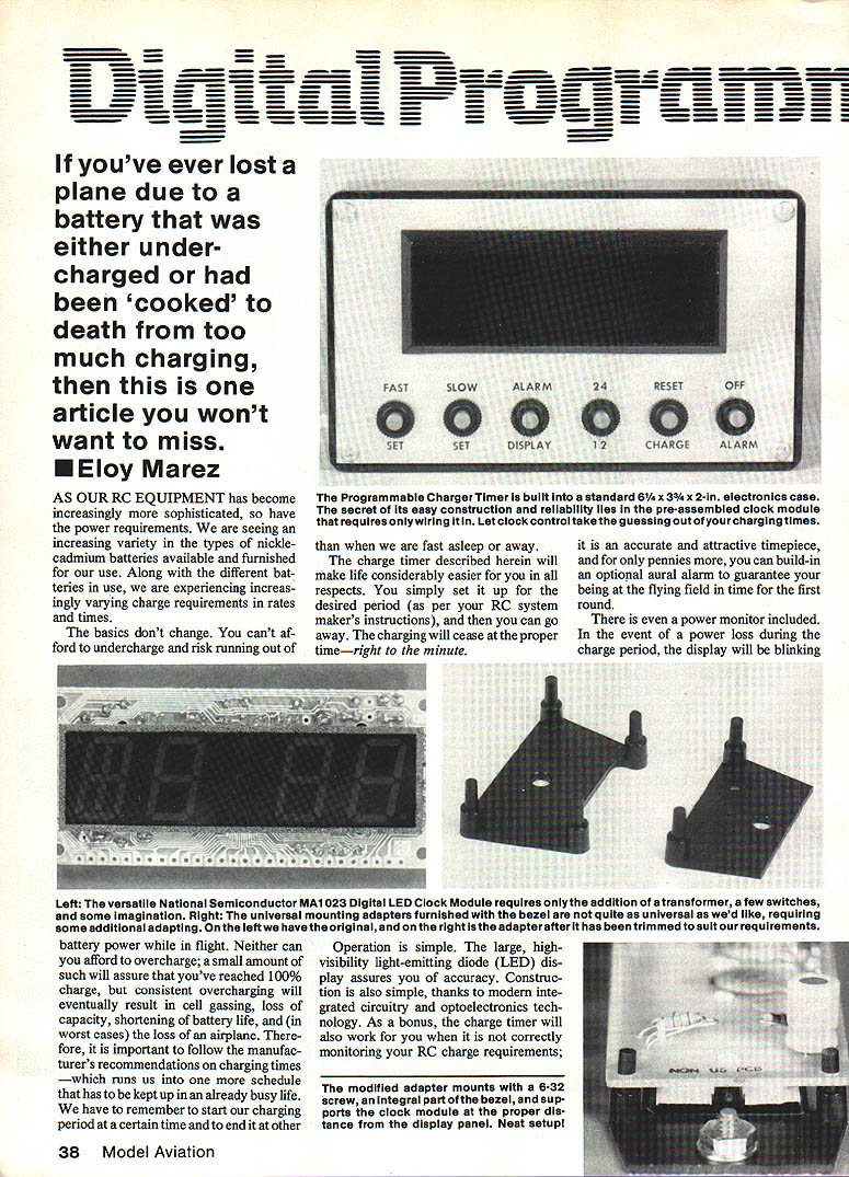
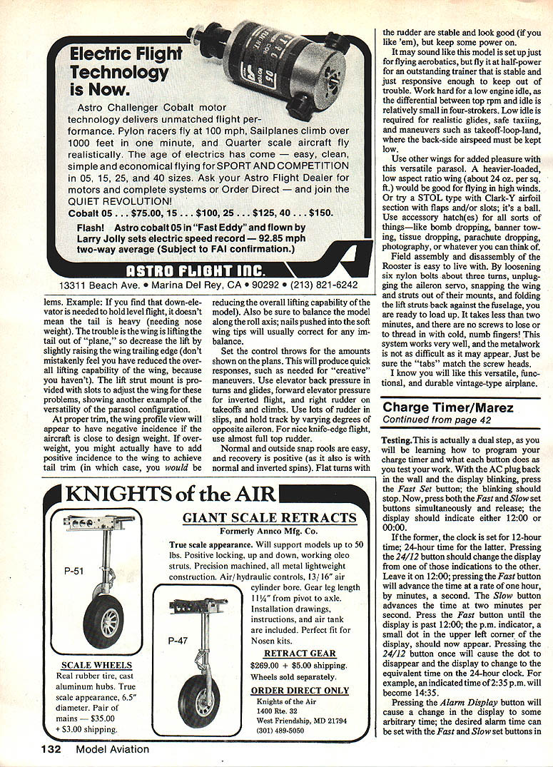
The Programmable Charger Timer is built into a standard 6-1/4 x 3-3/4 x 2-in. electronics case. The secret of its easy construction and reliability lies in the preassembled clock module that requires only wiring in. Let a clock control take the guessing out of your charging times.
The charge timer described herein will make life considerably easier. You simply set it for the desired period (as per your RC system maker's instructions), then you can go away. Charging will cease at the proper time — right to the minute.
It is an accurate and attractive timepiece, and for only pennies more you can build in an optional aural alarm to guarantee being at the flying field in time for the first round.
There is even a power monitor included. In the event of a power loss during the charge period, the display will blink. When power returns, all pre-set information will be lost and charging will have restarted upon the return of AC power. Unless you can determine how long the power was off, you won't know how much charging time was lost, but that is better than no warning and then flying with batteries you assumed were properly charged when they were not.
Operation is simple. The large, high-visibility light-emitting diode (LED) display assures you of accuracy. Construction is also simple, thanks to modern integrated circuitry and optoelectronics technology. As a bonus, the charge timer will also work for you when it is not directly monitoring your RC charge requirements.
Circuit
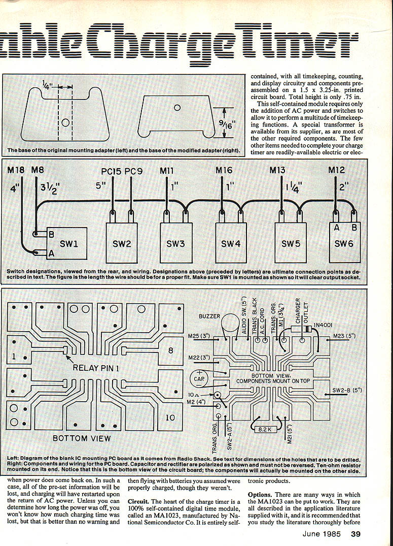
The heart of the charge timer is a 100% self-contained digital time module, the MA1023, manufactured by National Semiconductor Co. It is entirely self-contained, with all timekeeping, counting, and display circuitry and components preassembled on a 1.5 x 3.25-in. printed circuit board. Total height is only 0.75 in.
This module requires only the addition of AC power and switches to allow it to perform a multitude of timekeeping functions. A special transformer is available from its supplier, as are most of the other required components. The few other items needed to complete your charge timer are readily available electronic products.
Options
There are many ways the MA1023 can be put to work. All are described in the application literature supplied with it, and it is recommended you study that literature thoroughly before ordering parts so you can tailor your charge timer and parts buying exactly to your needs.
Examples:
- You may not need the audio alarm feature. Simply leave it off, don't purchase the required parts, and adjust the panel spacing for only five switches.
- If you plan on using the alarm feature daily, you might want a "snooze" feature, which gives you an extra 9 minutes to wake up each time you press the button.
- For countries with 50-cycle mains, add a jumper for the timer to keep correct time.
- If you don't care for the 12–24-hour selectable feature, leave off that switch and it will display in a 12-hour format. If you prefer a constant 24-hour timepiece, one jumper will give you that.
First of all, let's go shopping. You'll need the following items, available from Digi‑Key Corporation, Highway 32 South, Box 677, Thief River Falls, MN 56701. Telephone credit card orders are accepted toll-free at 800/346-5144; for other information, call 218/681-6674.
- 1 MA1023M Clock Module — $11.70
- 1 MA1023T Transformer — $3.95
- 1 MA1023B Buzzer — $3.10
- 1 400 Bezel w/ red filter — $4.95
- 1 422 Universal Bezel Adapter — $0.69
- 2 501PB Switches @ $0.56 — $1.12
- 3 502PB Switches @ $0.56 — $1.68
- 1 503PB Switch @ $0.56 — $0.56
- 1 700KD-ND Instrument Box — $3.50
- 1 2046K-ND Aluminum Panel — $1.37
- 1 F004-ND Panel Fuseholder — $0.95
- 1 F115-ND 1-Amp Fuses, 5 — $1.24
- 1N4001 Rectifier Diode, 10-pack — $0.80
- 1 SW104-ND SPDT Switch — $0.34
- 1 488C Line Cord — $0.35
- 1 10 Ohm 1/4 Watt Resistor, 5-pack — $0.25
- 1 8.2K 1/4 Watt Resistor, 5-pack — $0.25
- 1 P6620 100V/16V Capacitor — $0.27
All of the above items are fully described in the Digi‑Key catalog, available on request from the above address. In addition, you will need the following locally procured items:
- 1 Radio Shack Relay, No. 275-215
- 1 Radio Shack Single IC Board, No. 276-024
- 1 Radio Shack Aluminum Spacers, No. 64-3024
- 1 Leviton No. 5015-1 Receptacle (see text)
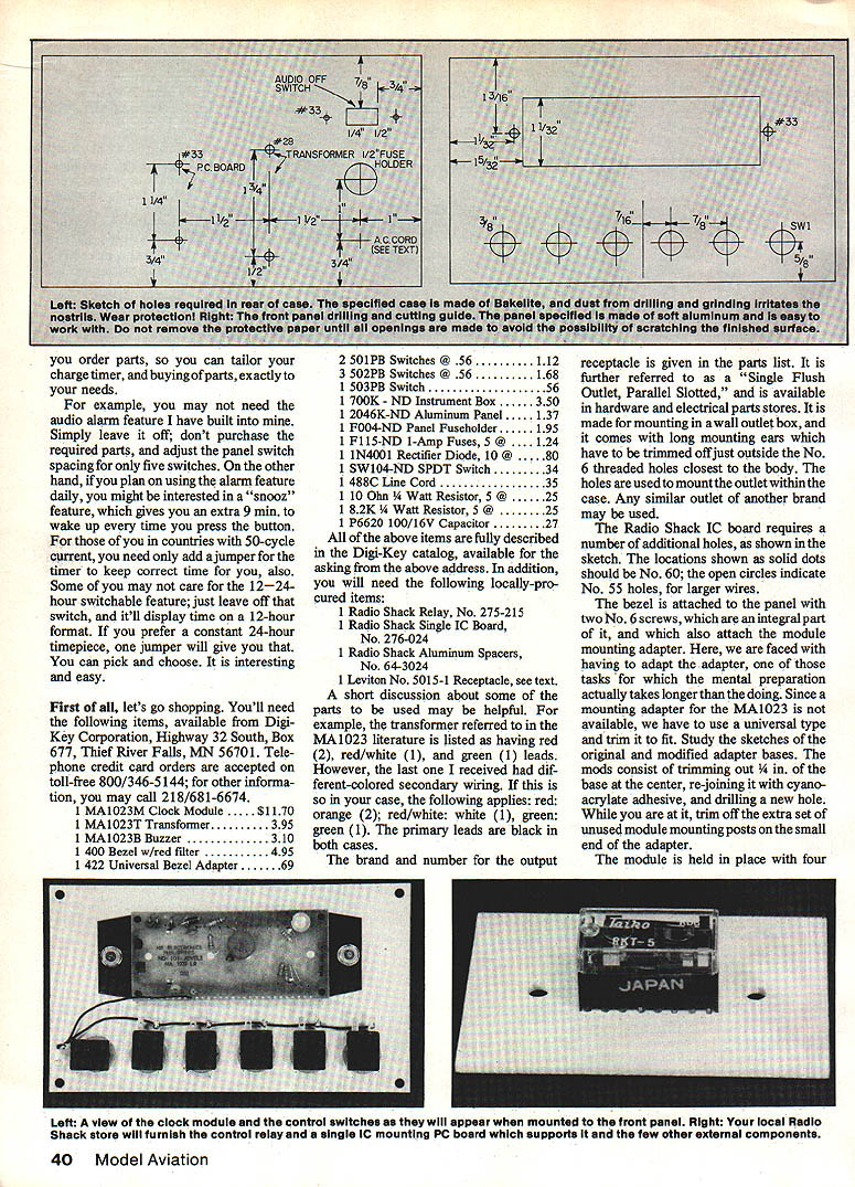
A short discussion about some parts may be helpful. For example, the transformer referred to in the MA1023 literature is listed as having red (2), red/white (1), and green (1) leads. However, the last one I received had different-colored secondary wiring. If this is so in your case, the following applies: red = orange (2); red/white = white (1); green = green (1). The primary leads are black in both cases.
The output receptacle (Leviton No. 5015-1) is referred to as a "Single Flush Outlet, Parallel Slotted," and is available in hardware and electrical parts stores. It is made for mounting in a wall outlet box and comes with long mounting ears which must be trimmed off just outside the No. 6 threaded holes closest to the body. The holes are used to mount the outlet within the case. Any similar outlet of another brand may be used.
The Radio Shack IC board requires a number of additional holes, as shown in the sketch. Locations shown as solid dots should be No. 60; open circles indicate No. 55 holes for larger wires.
The bezel is attached to the panel with two No. 6 screws, which are an integral part of it and which also attach the module to the mounting adapter. Since a specific mounting adapter for the MA1023 is not available, use a universal type and trim it to fit. Study the sketches of the original and modified adapter bases. The pads consist of trimming out 1/4 in. of the base at the center, rejoining it with cyanoacrylate adhesive, and drilling a new hole. While you are at it, trim off the extra set of unused module-mounting posts on the small end of the adapter.
The module is held in place with four push-on clips furnished with the adapter. Do not permanently mount the module until all connections to it have been made and testing has been completed. You can temporarily hold the module in place on the adapter with small grommets or short lengths of fuel tubing slipped over the mounting posts.
There are two panels available for the case listed: the one I used and a similar one in black plastic. I chose the aluminum panel because it provides better contrast for photographs — and because, when lettered with black rub-offs and sprayed with a clear finish such as Super Poxy, it is extremely durable and attractive. Labels can be applied by any method you choose; one easy way is with a plastic tape writer.
All inter-unit connections will be made after individual parts (panel, case, and IC board) have had their components mounted and partly wired. To make this last step easier to understand, all connection points on the module are referred to as M1 through M28, from left to right looking at the front of the display. A very small "1" is printed on the first connecting hole on the left. The switches, as seen in the mounting sketch, are numbered SW1 through SW6, with connections designated A and B. The IC board lands have been assigned corresponding pin numbers of the relay, which uses the same system as for ICs.
Construction
We can now start actual construction.
- Case holes
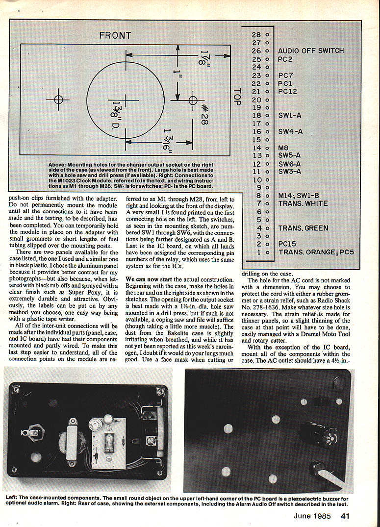
- Make the holes in the rear and on the right side as shown in the sketches. The opening for the output socket is best made with a 1 3/8-in. dia. hole saw mounted in a drill press; if not available, a coping saw and file will suffice.
- The dust from the Bakelite case can be irritating; use a face mask when cutting or drilling.
- AC cord hole
- The hole for the AC cord is not dimensioned. You may choose to protect the cord with a rubber grommet or a strain relief such as Radio Shack No. 278-1636. Make whatever size hole is necessary. The strain relief is made for thinner panels, so a slight thinning of the case at that point may be needed, easily managed with a Dremel Moto Tool and rotary cutter.
- Mount components (except IC board)
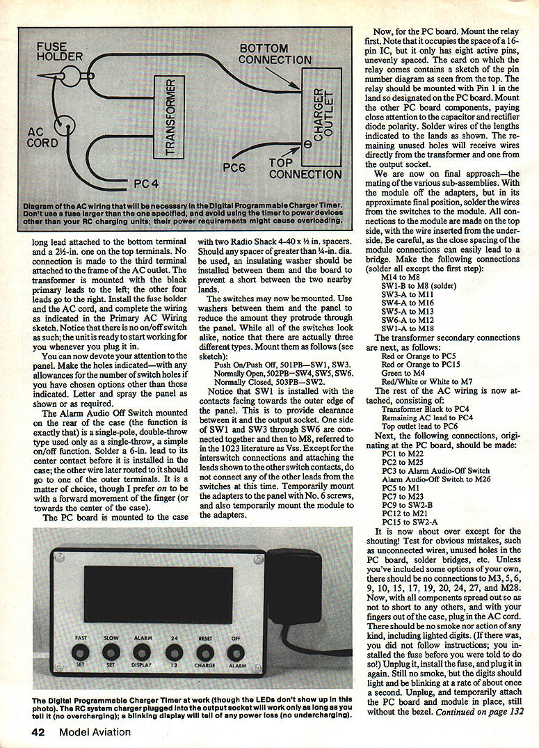
- Mount all components within the case except the IC board. The AC outlet should have a 4-1/4-in. lead attached to the bottom terminal and a 2-1/2-in. one on the top terminal. No connection is made to the third terminal attached to the outlet frame.
- Mount the transformer with the black primary leads to the left; the other four leads go to the right.
- Install the fuse holder and AC cord, and complete the wiring as indicated in the Primary AC Wiring sketch. Note there is no on/off switch; the unit starts working when you plug it in.
- Panel work
- Make the switch and bezel holes indicated, allowing for any options you selected. Letter and spray the panel as desired.
- Alarm Audio-Off Switch
- The Alarm Audio-Off Switch mounted on the rear is a single-pole double-throw switch used only as a single-throw (on/off). Solder a 6-in. lead to its center contact before installing in the case; the other wire later attached should go to one of the other two terminals. I prefer the "on" position to be a forward movement of the finger (toward the center of the case).
- PC board mounting
- The PC board is mounted to the case with two Radio Shack 4-40 x 1/2-in. spacers. If any spacer greater than 1/4-in. dia. is used, install an insulating washer between it and the board to prevent shorts.
- Switch mounting
- Use washers between the switches and the panel to reduce how far they protrude. There are three switch types; mount them as follows:
- Push On/Push Off, 501PB — SW1, SW3
- Normally Open, 502PB — SW4, SW5, SW6
- Normally Closed, 503PB — SW2
- Install SW1 with the contacts facing the outer edge of the panel to provide clearance to the output socket.
- One side of SW1 and SW3 through SW6 are connected together and then to M8 (Vss in the 1023 literature). Except for these interswitch connections and attaching the leads shown to the other switch contacts, do not connect other switch leads at this time.
- Temporarily mount the adapters to the panel with No. 6 screws and temporarily mount the module to the adapters.
- PC board assembly
- Mount the relay first. Note it occupies the space of a 16-pin IC but only has eight active pins, unevenly spaced. The relay card contains a pin-number diagram as seen from the top. Mount the relay with Pin 1 in the land designated Pin 1 on the PC board.
- Mount other PC board components, paying close attention to capacitor and rectifier diode polarity. Solder wires of the lengths indicated to the lands as shown. Unused holes will receive wires directly from the transformer and one from the output socket.
Final Wiring and Connections
With the module off the adapters but in approximate final position, solder the wires from the switches to the module. All connections to the module are made on the top side, with the wire inserted from the underside. Be careful: the close spacing of module connections can easily lead to solder bridges.
Make the following connections (solder all except the first step):
- M14 to M8 (solder)
- SW1-B to M8
- SW3-A to M11
- SW4-A to M16
- SW5-A to M13
- SW6-A to M12
- SW1-A to M18
Transformer secondary connections:
- Red or Orange to PC5
- Red or Orange to PC15
- Green to M4
- Red/White or White to M7
Remaining AC wiring:
- Transformer Black to PC4
- Remaining AC lead to PC4
- Top outlet lead to PC6
Connections originating at the PC board:
- PC1 to M22
- PC2 to M25
- PC3 to Alarm Audio-Off Switch
- Alarm Audio-Off Switch to M26
- PC5 to M1
- PC7 to M23
- PC9 to SW2-A
- PC12 to M21
- PC15 to SW2-A
There should be no connections to M3, M5, M6, M9, M10, M15, M17, M19, M20, M24, M27, and M28 unless you've included optional features.
Testing
Test for obvious mistakes such as unconnected wires, unused holes in the PC board, solder bridges, etc. With all components spread out so as not to short to any others and with your fingers out of the case, plug in the AC cord. There should be no smoke nor action of any kind, including lighted digits. (If there is, you likely installed the fuse before you were told to do so.) Unplug, install the fuse, and plug in again. Still no smoke, but the digits should light and blink at about once per second.
Unplug, temporarily attach the PC board and module in place (still without the bezel), and proceed with the following functional tests. This will both verify wiring and teach you how to program the timer.
- With the AC plug in and the display blinking, press the Fast set button; the blinking should stop.
- Press both Fast and Slow set buttons simultaneously and release; the display should indicate either 12:00 or 00:00.
- 12:00 indicates the clock is set for 12-hour time.
- 00:00 indicates 24-hour time.
- Pressing the 24/12 button toggles between 12- and 24-hour modes. Leave it on 12:00 for initial testing.
- Press the Fast button to advance time at one hour per second. The Slow button advances time at two minutes per second.
- Advance past 12:00; the p.m. indicator (a small dot in the upper left of the display) should appear. Press the 24/12 button once to switch to the equivalent 24-hour display (for example, 2:35 p.m. becomes 14:35).
- Pressing the Alarm Display button changes the display to the alarm time; set the desired alarm time with Fast and Slow buttons. Depressing Fast, Slow, and Alarm Display simultaneously will reset the alarm time to 12:00 or 00:00.
- The Charge Reset button has no visible effect now but is used to restart a charge cycle after an On/Off cycle; it will be explained under Operation.
- The Off Alarm button stops the alarm sound and indicates the alarm is armed by lighting a small red dot in the lower right of the display. The alarm must be armed for the charger to be shut off at the desired time. The Alarm Audio switch on the rear works with this feature to provide audible beeps or to silently terminate charging.
To test the charge output, plug a lamp (less than 100 watts) into the outlet. Cycle the timer as before; the lamp will be on during the normal time and will go off when the current time advances to coincide with the alarm-set time.
Once you become familiar with the switches, operation becomes straightforward.
Operation
A couple of operational notes:
- The 24/12 feature is useful if you want to use the unit to control only the charge time rather than as a timepiece or alarm. Set it to 24 hours, zero both the indicated and alarm times, then set the desired charge period in the alarm time. The alarm must be on; when the proper time has elapsed charging will automatically cease.
- Alternatively, set the actual correct time (12- or 24-hour), add the desired charge time to the present time, and enter that sum as the alarm time.
- The Reset Charge button must be used to start a charge cycle after the charge timer has been through an On/Off cycle once (either as an alarm or on actual time). This resetting action places the timer back into its initial plugged-in state. If you have been cycling it for testing, press this button momentarily after setting all times. Actual charging action can be checked by the LED indicator present on most RC-system chargers.
If everything works normally, complete final assembly by installing the bezel, filter, and adapter.
Charge Timer — Marez (continued)
After removing the protective covering from the bezel filter, note there is a shiny and a dull side; install it with the dull surface outward. As you install the panel into the case, check for obstructions. If you used the components and dimensions given, no problems should arise. Install the panel screws, and admire the result.
More importantly, using your Digital Programmable Charge Timer in conjunction with the instructions furnished by the maker of your RC system will assure safe and complete charging of Ni-Cd batteries — without fear of overcharging.
Parts update: the latest Digi-Key catalog lists a relay, Part No. Z310-ND, priced at $3.35, which is identical in size and pin connections to the Radio Shack unit previously mentioned. You can save an extra trip by including this in your initial order for parts.
Transcribed from original scans by AI. Minor OCR errors may remain.

