
Dihedral
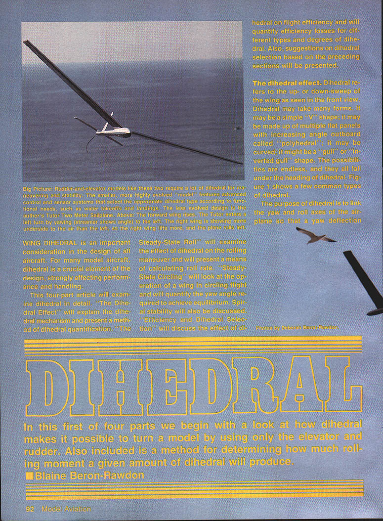
WIng dihedral is an important consideration in the design of all aircraft. For many model aircraft, dihedral is a crucial element of the design, strongly affecting performance and handling.
This article is the first of a four-part series that examines dihedral in detail:
- The Dihedral Effect — explains the dihedral mechanism and presents a method of dihedral quantification.
- The Steady-State Roll — examines the effect of dihedral on the rolling maneuver and presents a means of calculating roll rate.
- Steady-State Circling — looks at the operation of a wing in circling flight, quantifying the yaw angle required to achieve equilibrium; spiral stability is also discussed.
- Efficiency and Dihedral Selection — discusses the effect of dihedral on flight efficiency, quantifies efficiency losses for different types and degrees of dihedral, and offers suggestions on dihedral selection based on the preceding sections.
By Blaine Beron-Rawdon
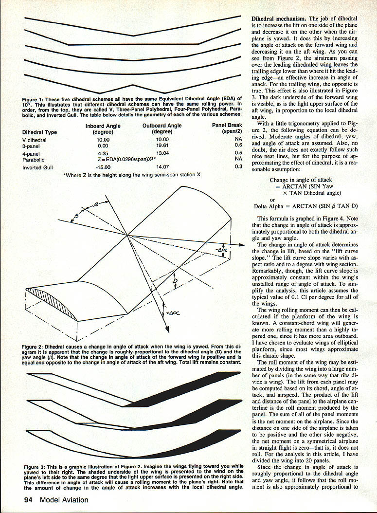
Dihedral refers to the up- or down-sweep of the wing as seen in the front view. Dihedral can take many forms: a simple "V" shape; multiple flat panels with increasing angle outboard ("polyhedral"); curved wings; "gull" or "inverted gull" shapes; and many other configurations. All of these arrangements fall under the heading of dihedral (see Figure 1 for common types).
The purpose of dihedral is to link the yaw and roll axes of the airplane so that a yaw deflection causes a rolling moment. This "yaw–roll couple" enables an airplane to be maneuvered with only rudder and elevator control. It can also be tuned to provide spiral stability so that the airplane can be trimmed to fly hands-off without slowly rolling over and diving in.
In radio-control (RC) models without ailerons, dihedral is used principally to provide roll control from a rudder input. In RC models with ailerons and in Free Flight models, dihedral is used principally to provide spiral stability. In RC Pattern ships, dihedral is sometimes tuned so that roll is decoupled from yaw, allowing knife-edge maneuvers to be flown without aileron bias.
Other means to provide roll control include ailerons (used almost universally on full-size aircraft and most powered RC models), roll spoilers (occasionally used), wing sweep (which causes a yaw–roll couple but with important differences from dihedral), and fuselage interference effects that can create a yaw–roll couple similar to dihedral.
Spiral stability may be provided either by tuning the yaw–roll couple or by artificial gyroscopic control. Many full-size aircraft designs—constrained by engine-out, weight, and efficiency concerns—cannot tune for natural spiral stability and must rely on the pilot or on an artificial system.
This article is addressed principally to rudder-and-elevator RC sailplanes. These planes are characterized by low flying speeds, large spans, and minimal fuselages. Many Free Flight models share these characteristics, but for RC models more attention is paid to maneuvering than to spiral stability. The information presented can be applied to powered RC models, with the proviso that fuselage interference effects may cause some inaccuracies.
Dihedral mechanism
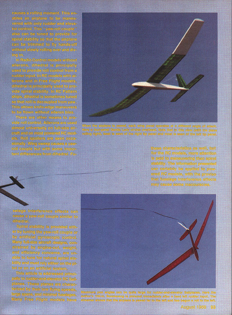
The job of dihedral is to increase the lift on one side of the airplane and decrease it on the other when the airplane is yawed. It does this by increasing the effective angle of attack on the forward wing and decreasing it on the aft wing. As illustrated in Figures 2 and 3, the airstream passing a wing with dihedral leaves the trailing edge lower (relative to the incoming flow) on the forward wing—an effective increase in local angle of attack—while the trailing wing experiences the opposite.
With modest assumptions (moderate dihedral, yaw, and angle of attack) and a simple trigonometric model, the change in local angle of attack produced by yaw can be approximated by:
Change in angle of attack = arctan( sin(yaw) × tan(dihedral angle) )
or
Delta Alpha = ARCTAN( SIN β × TAN D )
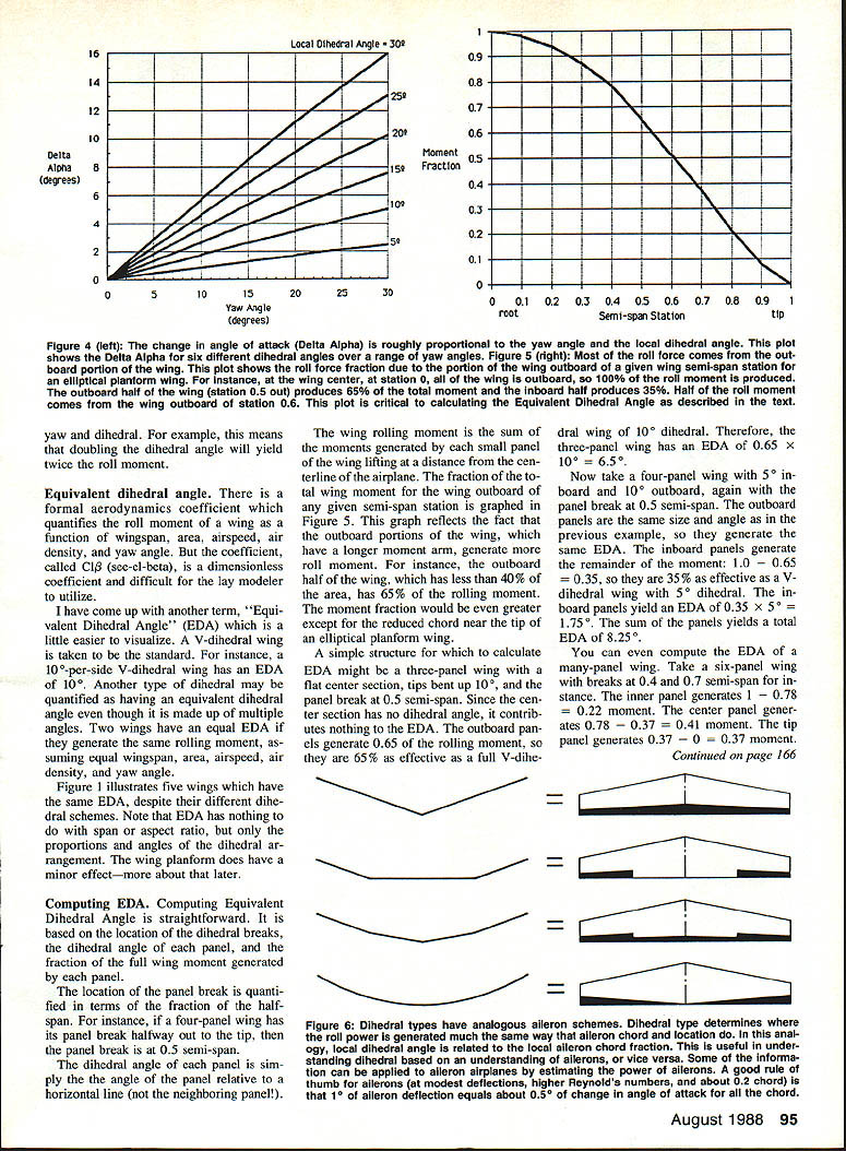
This relation is plotted in Figure 4. For small angles, the change in angle of attack is approximately proportional to both the dihedral angle and the yaw angle. The change in angle of attack determines the change in lift through the lift curve slope. The lift curve slope varies with aspect ratio and, to a degree, with section; however, it is approximately constant within the wing’s unstalled range. For simplicity, this article assumes a typical lift-curve slope of 0.1 Cl per degree.
The wing rolling moment can be calculated if the wing planform is known. A constant-chord wing will generate more rolling moment than a highly tapered one for the same outboard geometry, since it has more area outboard. Elliptical planform is often used for analysis because most wings approximate that classic shape.
To estimate roll moment, divide the wing into many small panels (as ribs divide a wing). Compute the lift from each panel based on its chord, effective angle of attack, and airspeed. The product of the lift and the panel’s distance from the airplane centerline is the roll moment contributed by that panel. Sum all panel moments (taking one side positive and the other negative). For a symmetric airplane in straight flight, the net moment is zero. In the examples here, the wing is divided into 20 panels.
Because the change in angle of attack is roughly proportional to dihedral angle and yaw angle, the roll moment is also approximately proportional to yaw and dihedral. Doubling the dihedral angle will approximately double the roll moment.
Equivalent dihedral angle
There is a formal aerodynamic coefficient that quantifies the roll moment of a wing as a function of wingspan, area, airspeed, air density, and yaw angle: the coefficient C_lβ. C_lβ is dimensionless and can be difficult for the lay modeler to use directly.
I introduce the term "Equivalent Dihedral Angle" (EDA) as an easier-to-visualize measure. A V-dihedral wing is taken as the standard: a 10°-per-side V-dihedral wing has an EDA of 10°. Any other dihedral arrangement may be assigned an EDA equal to the dihedral angle of a V-wing that would produce the same rolling moment under the same wingspan, area, airspeed, air density, and yaw angle.
EDA depends on the dihedral geometry (panel locations and angles) and planform proportions, but not on span or aspect ratio for a given planform shape. Figure 1 illustrates several wings that share the same EDA despite different dihedral schemes. The wing planform has a minor effect on EDA, discussed below.
Computing EDA
Computing Equivalent Dihedral Angle is straightforward. It is based on the locations of the dihedral breaks, the dihedral angle of each panel, and the fraction of the full wing moment generated by each panel.
- Panel break location is expressed as a fraction of the half-span (semi-span). For example, if a four-panel wing has its panel break halfway to the tip, the panel break is at 0.5 semi-span.
- The dihedral angle of each panel is the angle of that panel relative to a horizontal reference (not relative to adjacent panels).
- The wing rolling moment is the sum of the moments generated by each panel lifting at its distance from the centerline. The fraction of the total wing moment contributed by wing outboard of any semi-span station is graphed in Figure 5. Because outboard portions have a longer moment arm, they contribute disproportionally more roll moment. For an elliptical planform, the outboard half of the wing—though having less than 40% of the area—accounts for about 65% of the rolling moment.
Example calculations:
- Three-panel wing: full center section (flat), tips bent up 10°, panel break at 0.5 semi-span. The center section contributes nothing to dihedral. The outboard panels generate 0.65 of the rolling moment, so the EDA = 0.65 × 10° = 6.5°.
- Four-panel wing: 5° inboard and 10° outboard, panel break at 0.5 semi-span. Outboard panels contribute 0.65 × 10° = 6.5°. Inboard panels contribute 0.35 × 5° = 1.75°. Total EDA = 6.5° + 1.75° = 8.25°.
- Six-panel wing with breaks at 0.4 and 0.7 semi-span: inner panel moment fraction = 1.0 − 0.78 = 0.22; center panel = 0.78 − 0.37 = 0.41; tip panel = 0.37 − 0 = 0.37. Multiply each panel’s moment fraction by its dihedral angle and sum to find the wing’s EDA.
All moment fractions for each panel are multiplied by the panel dihedral angle and summed to find the EDA. Figure 1 provides additional examples of different arrangements that all yield an EDA of 10°.
Analogy with ailerons
The dihedral distribution along the span determines where roll power is generated when the airplane yaws. For example:
- A plane with a flat center panel contributes nothing from the center; the tip panels supply most of the roll power. This is analogous to an aileron arrangement with partial-span or "barn-door" ailerons.
- A V-dihedral wing produces approximately equal delta-alpha all along the wing; this is analogous to strip ailerons whose effectiveness is proportional to local chord.
These analogies can be used to understand aileron effectiveness. From Figure 4, 0.5 semi-span barn-door ailerons will be about 65% as powerful as full-span strip ailerons of the same percentage chord.
Transitional maneuvers
While steady-state maneuvers (rolling and circling) are handled well by rudder and elevator on most airplanes, transitional maneuvers—such as initiating or ending a roll—are a weak point. Transition requires a sequence of events:
- A large rudder deflection accelerates the airplane in yaw.
- As the airplane yaws, it begins to accelerate in roll.
- As yaw approaches the steady-state maximum for the rudder deflection, yaw decelerates until the maximum yaw angle is reached (underdamped yaw can cause overshoot and brief oscillation).
- Shortly after the maximum yaw angle is reached, maximum roll rate is achieved.
- Rudder is held until the desired bank is approached, then neutralized; the airplane pays back to zero yaw and stops rolling (again with acceleration/deceleration delays).
To roll, the airplane must first yaw; to stop rolling, it must stop yawing. Minimizing lag between control input and response requires maximizing yaw and roll accelerations and decelerations. This is achieved by:
- Large fin/rudder,
- Long tail moment arm,
- Generous dihedral,
- Lightweight extremities (wing tips, tail group).
If extremities are heavy and the vertical stabilizer is undersized or on too short a moment arm, the airplane will be slow to respond and prone to overshoot and oscillation. The pilot must then use very slow, smooth inputs, sacrificing the potential for rapid, precise control.
Insufficient dihedral requires larger yaw excursions to generate a given roll response, making the airplane sluggish and reducing maximum roll rate. Conversely, ample dihedral combined with lightweight extremities, long tail moment arm, and a large vertical stabilizer produces immediate, precise, and powerful handling.
General comments
- For a given airplane, roll moment from dihedral is a function of yaw angle and airspeed. Within the wing’s unstalled range, the overall angle of attack (trim angle) is not important: if speed and yaw angle are the same, the roll moment is the same. It is the local effective angle of attack that determines the change in lift. Washout, twist, and section variation can change local dihedral effectiveness.
- EDA is a convenient operational summary of yaw–roll coupling for small yaw angles, useful for comparing wings. It is not a fundamental property and may become nonlinear at large yaw angles.
- Roll moment is generated by equal and opposite changes in angle of attack between left and right wings. Because the change in lift, not the base lift, matters, the base angle of attack is not important.
- Yawing the airplane does not change total lift (left plus right) because the increases and decreases cancel; this makes it possible to roll into a thermal without simultaneous pitch compensation.
- High rates of yaw and roll may cause gyroscopic coupling of the yaw and roll axes, producing an unexpected pitch-up due to gyroscopic precession. This is generally not an issue in coordinated aileron aircraft where only one axis is being spun at a time.
- Swept wings couple yaw and roll differently from dihedral. A yawed swept wing generates roll moment by a difference in effective span: both wings still produce roughly the same lift, but one wing is effectively longer and thus has more leverage. Therefore, roll moment from sweep relates to total lift and flight g-loading:
- At a constant 1° yaw, the roll moment from sweep is independent of speed.
- At higher g (e.g., 3 g), the roll moment from sweep scales with total lift (three times greater at 3 g).
- In 0-g (no lift) conditions, a swept wing produces no roll moment from yaw.
- If inverted, the roll moment from sweep reverses sign for the same yaw.
For RC models, a pure swept-wing model without dihedral or ailerons can be very tricky to fly. For swept wings with ailerons, careful rudder coordination prevents unexpected responses.
Summary and conclusions
- Dihedral arrangement is crucial to handling in the roll axis.
- Dihedral provides a coupling between yaw and roll that is roughly proportional to Equivalent Dihedral Angle (EDA) and yaw angle.
- The rolling moment of a wing can be computed from its dihedral arrangement, yaw angle, airspeed, wingspan, wing area, and planform.
- Dihedral arrangements that generate the same roll moment as a V-dihedral wing are said to have an Equivalent Dihedral Angle equal to that V-dihedral angle.
- EDA may be calculated easily by summing the products of panel moment fractions and panel dihedral angles.
- Various dihedral arrangements have analogies in aileron arrangements.
- Transitional maneuvers are the weak point of rudder-and-elevator airplanes; generous dihedral, long tail moment arm, large vertical stabilizer, and lightweight wing tips and tail group minimize transitional shortcomings.
- The roll moment of a dihedral wing is independent of the overall angle of attack (within the unstalled range).
- Swept wings behave quite differently from dihedral wings and must be handled accordingly in design and flying technique.
Transcribed from original scans by AI. Minor OCR errors may remain.

