
Dihedral
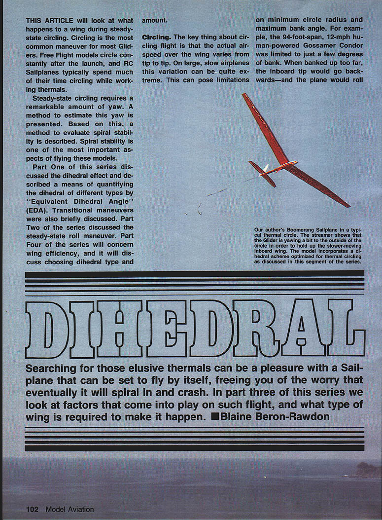
This article examines what happens to a wing during steady-state circling. Circling is the most common maneuver for most gliders: Free Flight models circle constantly after launch, and RC sailplanes typically spend much of their time circling while working thermals.
Steady-state circling requires a remarkable amount of yaw. A method to estimate this yaw is presented, and based on it a method to evaluate spiral stability is described. Spiral stability is one of the most important aspects of flying these models.
Part One of this series discussed the dihedral effect and described a means of quantifying dihedral by the Equivalent Dihedral Angle (EDA). Part Two discussed the steady-state roll maneuver. Part Four will concern wing efficiency and choosing dihedral type and amount. This article (Part Three) looks at factors in steady circling flight and what type of wing is required to make it happen.
Circling
The key feature of circling flight is that the actual airspeed over the wing varies from tip to tip. On large, slow airplanes this variation can be extreme and can limit minimum circle radius and maximum bank angle. For example, the 94-ft-span, 12-mph human-powered Gossamer Condor was limited to just a few degrees of bank; when banked too far, the inboard tip could go backwards and the plane would roll.
These limitations arise because the differential airspeed on the wing causes more lift on the outboard wing and less on the inboard. This makes the airplane want to roll to the inside of the circle.
Where the Gossamer Condor used twist and full-size sailplanes use ailerons, most gliding models use dihedral. To hold up the inboard wing, dihedral models must yaw outboard. That fact is the crux of this article: what determines how much the model must yaw (and how much does it yaw)?
Lift distribution
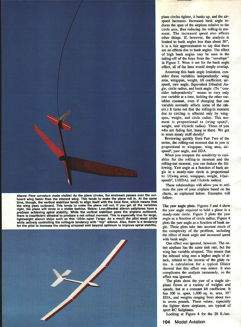
In a steady-state circle the bank angle is constant, so the net rolling moment on the airplane must be zero. The rolling moment may be estimated by dividing the wing into bays (like ribs). The lift on each bay is calculated from its area, angle of attack, and local airspeed. The moment of each bay is lift times its distance from the airplane centerline. Dividing the wing into many bays increases accuracy; the graphs described here used a wing divided into 20 bays.
While circling, the outboard bays have higher airspeed and generate more lift if the wing is unyawed. The total lift of the circling airplane is greater because more lift is required to support the plane in a bank. To counteract the rolling-in moment the plane must yaw outboard so the inner bays have a higher angle of attack, redistributing lift inboard. Different dihedral geometries (parabolic, multi-panel polyhedral, and simple V-dihedral) produce different lift redistributions: parabolic dihedral yields an almost symmetrical lift distribution; V-dihedral tends to load up the inboard portion of the inboard wing and unload the inboard tip.
Yaw while circling
A steady-state circle is achieved when the rolling-in moment due to unequal airspeed is exactly opposed by a rolling-out moment due to yaw. The variables that determine the rolling-in moment are interwoven, but by limiting analysis to moderate bank angles (less than about 30°) the problem simplifies: bank-angle effects can be reasonably ignored, and variables can be considered independently (vary one while holding others constant).
Under this approximation:
- The rolling-in moment due to circling is mainly affected by wingspan, weight, and circle radius, and is roughly proportional to (wingspan)^2 × weight ÷ circle radius.
- The rolling-out moment due to yaw (dihedral effect) is proportional to wingspan × wing area × airspeed^2 × yaw angle and inversely proportional to EDA.
Comparing these sensitivities leads to the conclusion that the yaw angle required for a given bank angle in steady-state circling is proportional to:
- wingspan × weight × (1 ÷ circle radius)
and inversely proportional to:
- wing area × airspeed^2 × EDA
Thus yaw ∝ (span × weight ÷ circle radius) ÷ (area × airspeed^2 × EDA). These relationships allow estimation of yaw from charts or by ratioing variables.
Yaw-angle plots and limitations
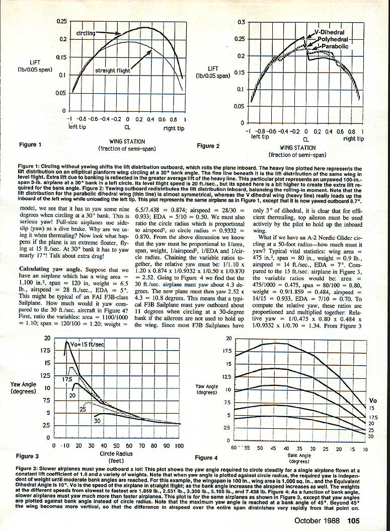
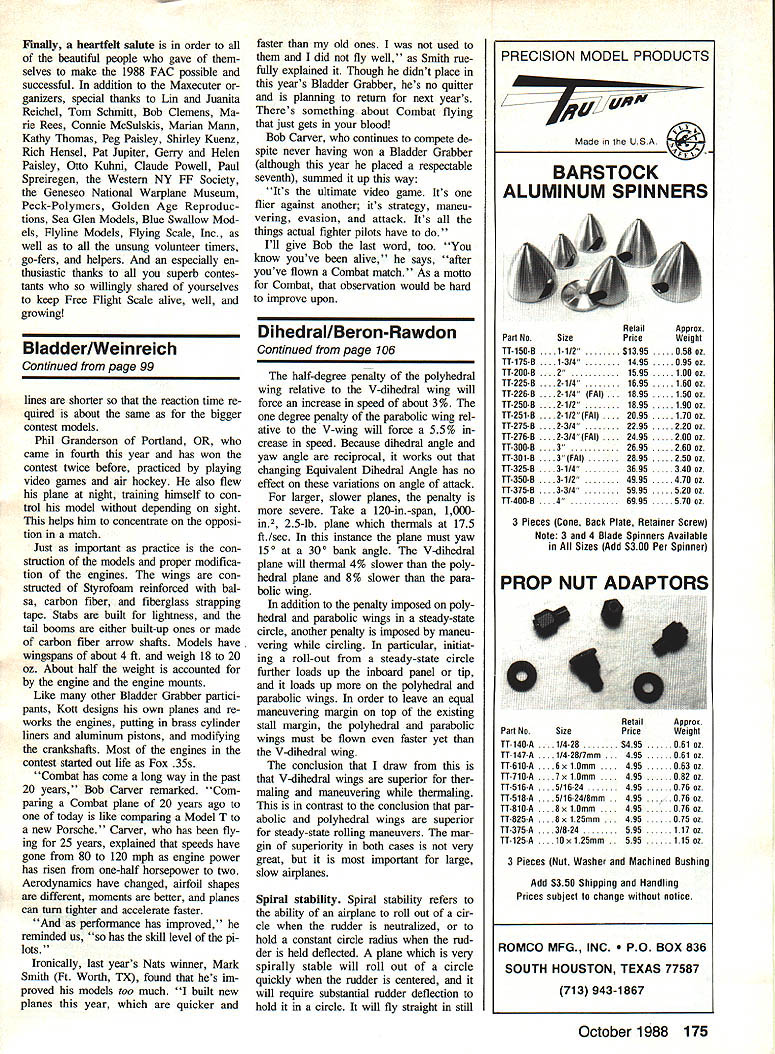
Yaw-angle plots (Figures referenced in the original paper) show required yaw versus circle radius and versus bank angle for a baseline airplane: 100 in span, 1,000 sq in area, 10° EDA, weights 2–7 lb, and various airspeeds. The plots include much complexity but ignore some minor effects for simplicity, such as the slight change in angle of attack due to the wing having variable airspeed while the whole airplane has the same sink rate; this effect is minor and complicates the analysis, so it was neglected.
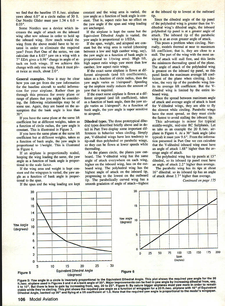
For example, the 20 ft/sec (≈20 ft/s) baseline model must yaw about 9.6° when circling at a 30° bank. A slower “floater” at 15 ft/sec needs nearly 17° of yaw at the same bank—producing substantial extra drag.
Calculating yaw angle — example
Suppose an airplane has: area = 1,100 in^2, span = 120 in, weight = 6.5 lb, airspeed = 28 ft/sec, EDA = 5°. Compare it to the baseline 1000 in^2 / 100 in / 7.38 lb / 30 ft/sec / 10° EDA airplane referenced in the plots.
Compute ratios to the baseline:
- area: 1100 / 1000 = 1.10
- span: 120 / 100 = 1.20
- weight: 6.5 / 7.38 = 0.874
- airspeed: 28 / 30 = 0.9333 → circle radius ∝ airspeed^2 → 0.9333^2 = 0.870
- EDA: 5 / 10 = 0.50
Yaw scales as 1/area × 1/span × weight × 1/airspeed^2 × 1/EDA × 1/circle-radius-term. Chaining ratios: 1/1.10 × 1/1.20 × 0.874 × 1/0.9333 × 1/0.870 ≈ 2.52.
If the baseline plane yaws about 4.3° at 30 ft/sec, the new plane must yaw ≈ 2.52 × 4.3 ≈ 10.8°. Thus an F3B-class sailplane with only ~3° geometric dihedral would need active top aileron input to hold the inboard wing for efficient thermalling.
Another example: an A-2 Nordic glider circling at a 50-ft radius with area = 475 in^2, span = 80 in, weight = 0.9 lb, airspeed = 14 ft/sec, EDA = 7°. Ratioing to baseline and multiplying factors gives a relative yaw ≈ 1.34. If baseline yaw at 15 ft/sec is ≈5°, the Nordic needs ≈1.34 × 5 ≈ 6.7° of yaw — large enough that top‑aileron trim or pilot input helps efficient thermalling.
Some Nordic free-flight designs use a device to increase inboard wing angle of attack after tow release. To eliminate the required yaw by rotating only one wing panel, the tip would need to pivot about twice the EDA-induced angle change; for example, a 8.03° yaw on a wing with 7° EDA gives a 0.98° change in AoA on both wings, so achieving that change on one wing alone would require about 2° pivot.
General relationships
(Assuming bank angle < 30° and constant lift coefficient)
- For the same plane at different weights (plotted vs. circle radius): yaw angle is constant.
- For the same plane at different weights (plotted vs. bank angle): yaw angle ∝ 1/weight.
- If an airplane is proportionally scaled keeping wing loading the same, yaw angle as a function of bank angle ∝ scale factor.
- If wing area and weight are constant and wingspan is varied, yaw angle ∝ span.
- If span and wing loading are constant and wing area is varied, yaw angle is constant (aspect ratio has no effect when span and wing loading are unchanged).
- If the airplane is unchanged but EDA is varied, yaw angle ∝ 1/EDA.
- If span, weight, and airspeed are constant and wing area is varied, yaw angle ∝ 1/wing area (high-lift high‑aspect wings yaw more than low-camber, low-aspect wings).
- For the same airplane at different airspeeds, yaw angle ∝ 1/airspeed^2 (speeding up reduces required yaw significantly).
Dihedral types
Three prototypical dihedral types considered are V-dihedral, multi-panel polyhedral (four-panel similar to curved), and parabolic dihedral. Behavior differences while circling:
- V-dihedral: same angle of attack along each wing panel (higher inboard, lower outboard); limited spread between maximum and average AoA so less tendency to tip-stall; can be flown slower while thermalling.
- Polyhedral: highest AoA on the inboard tip panel; inboard tip panel may stall first.
- Parabolic: smooth gradation, highest at inboard tip and lowest at outboard tip; the very tip may limit overall lift coefficient.
Because models thermal near maximum lift coefficient, the panel with the highest AoA stalls first, limiting minimum thermalling speed. V-dihedral has the smallest spread and can fly slowest in a circle; parabolic has the most spread and must fly faster to avoid tip stall. Differences are minor for typical mid-size RC sailplanes but grow in importance for larger, slower airplanes.
Numerical example: for the 20 ft/sec baseline at 30° bank (≈9.6° yaw):
- V-dihedral inboard wing AoA ≈ +1.68° above average.
- Polyhedral with 13° tip dihedral: inboard tip ≈ +2.2° above average.
- Parabolic with ≈16° tips: inboard tip ≈ +2.7° above average.
A half-degree penalty of polyhedral vs V-dihedral forces about a 3% speed increase; a 1° penalty (parabolic vs V) forces about a 5.5% increase. For larger, slower airplanes penalties are more severe (example: a 120-in span plane yawing 15° at 30° bank — V-dihedral plane thermals about 4% slower than polyhedral and 8% slower than parabolic in that scenario).
Also, initiating roll-out from steady-state circle further loads the inboard panel or tip, affecting polyhedral and parabolic wings more; thus V-dihedral wings are superior for thermalling and maneuvering while thermalling, though parabolic/polyhedral may be better for steady-state rolling maneuvers. The margin is not huge but matters for large, slow planes.
Spiral stability
Spiral stability refers to:
- the ability of an airplane to roll out of a circle when the rudder is neutralized, or
- to hold a constant circle radius when the rudder is neutral as the plane rolls.
A spirally stable airplane will roll out quickly with rudder centered and requires substantial rudder to hold a circle. A neutrally stable airplane will remain in a circle with neutral controls. A spirally unstable airplane will circle tighter and steeper with neutral controls and will tend to spiral down unless continuously corrected.
Free Flight models must be spirally stable; RC sailplanes vary by pilot preference. Excess spiral stability demands a lot of control input to circle (a “doggy” feel), while some spiral stability helps the pilot sense thermals. The author prefers small-to-moderate spiral stability.
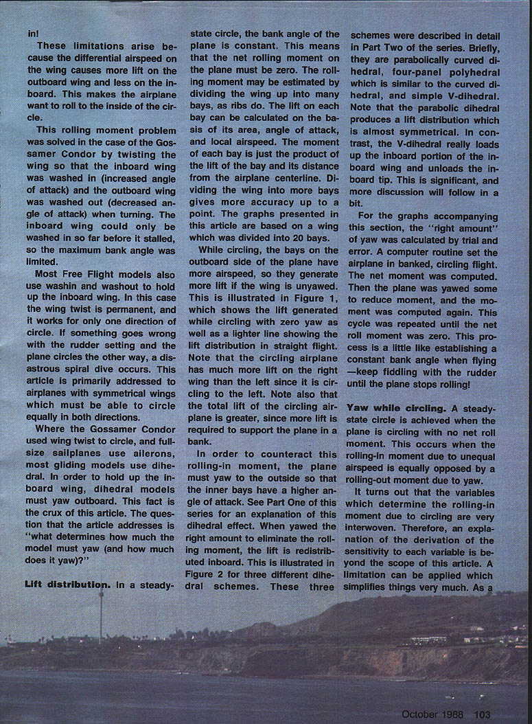
Causes of natural outboard yaw (that contribute to spiral stability):
- Flow curvature: as the plane flies a curved path the streamlines are curved. The vertical stabilizer, being aft of the wing, aligns with local flow and yaws the airplane outboard. The local curvature angle is approximately (tail moment arm ÷ circle perimeter) × 360°. Example: for a 25-ft radius circle (perimeter ≈ 157 ft) and a 3 ft distance between wing and vertical stab, the angle is ≈ (3/157)×360° ≈ 6.9°.
- Drag variation across the wing: the outboard wing experiences more drag in a circle, creating an outboard yawing moment that is opposed by the vertical stabilizer. The stabilizer generates lift by yawing further outboard of its neutral angle.
Key variables for spiral stability:
- natural yaw due to flow curvature: depends on distance between wing and vertical stabilizer, and circle radius,
- yaw due to wing drag variation: depends on drag variation (itself depending on circle radius, wing section, etc.) and on vertical stabilizer size, aspect ratio, and moment arm,
- vertical tail volume: quantified as (vertical tail area × vertical tail moment arm) ÷ (wing area × wing mean aerodynamic chord). Low aspect-ratio verticals have markedly different lift curve slopes and must be considered.
To achieve neutral spiral stability, the plane’s natural yaw angle from flow curvature/drag variation must equal the yaw angle required to balance the roll axis (as determined by dihedral, span, area, speed, etc.). You can either change the natural yaw (tail sizing or moment arm) or change the required yaw (increase EDA, change span/area/speed).
Practical points and trade-offs:
- A small vertical stab at a short moment arm can provide spiral stability (but risks poor damping and sluggish control).
- A large vertical stab at a long moment arm gives strong control and damping but adds drag and weight.
- If vertical tail and moment arm are both too small, Dutch-roll problems (a yaw-roll oscillation) can occur — undesirable for RC but sometimes used in Free Flight to help centering.
- For models it is often easier to adjust experimentally (cut and try) than to compute precisely, because fuselage effects and other unknowns matter.
An important additional effect: required yaw angle is sensitive to airspeed (yaw ∝ 1/airspeed^2). A design that is unstable at low speed may become stable at higher speeds. This means Free Flight models with insufficient spiral stability often cannot be trimmed to best glide speed: trimming to slow the model causes roll-in and a speed-up cycle; trimming faster improves stability but degrades thermal performance. The same applies to RC trainers: spiral stability degrades as the airplane slows for landing. To be spirally stable at all speeds, a plane must be spirally stable at its slowest speed.
Example of tail/dihedral trade: for the baseline 100-in span, 20 ft/sec plane that must yaw 9.6° at a 25-ft radius, putting a large vertical stabilizer 3.0 ft back from the wing yields a flow-curvature yaw of only ≈6.9°, so the plane would roll in. Solutions include lengthening the tail moment arm, increasing EDA (e.g., from 10° to 13.9°), or adjusting vertical tail size. Each has trade-offs.
Summary and conclusions
- Typical sailplane models exhibit substantial yaw angles during circling flight.
- While circling, spanwise airspeed variation generates a rolling-in moment; dihedral airplanes oppose this by yawing outboard. In steady-state the rolling-in moment is balanced by the rolling-out moment produced by dihedral and outboard yaw.
- For moderate bank angles, the rolling-in moment is proportional to wingspan^2 × weight ÷ circle radius. The rolling-out moment due to yaw is proportional to wingspan × wing area × airspeed^2 × yaw angle × EDA (or inversely proportional to EDA in some formulations). Comparing these moments shows yaw required ∝ (span × weight) ÷ (area × airspeed^2 × EDA × circle radius).
- These relationships allow estimation of yaw angle and provide guidance for design choices: dihedral amount, wing area, span, tail sizing, and flying speed.
- V-dihedral wings can be circled slower and have less tendency to tip-stall than polyhedral or parabolic wings; dihedral type influences minimum thermalling speed and behavior during maneuvers.
- Spiral stability may be increased by increasing dihedral, lengthening the vertical tail moment arm, or increasing vertical stabilizer area. Adequate spiral stability is essential for maximum circling performance.
- For a plane to be spirally stable at all speeds, it must be spirally stable at its slowest speed.
Transcribed from original scans by AI. Minor OCR errors may remain.

