
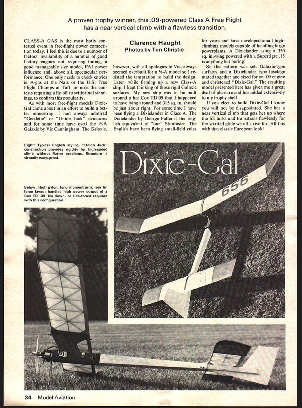
Dixie-Gal
A proven trophy winner, this .09-powered Class A Free Flight has a near vertical climb with a flawless transition.
Clarence Haught Photos by Tim Christie
CLASS-A GAS is the most hotly contested event in free-flight power competition today. I feel this is due to a number of factors: availability of a number of good factory engines not requiring tuning, a good manageable size model, FAI power influence and, above all, spectacular performance. One only needs to check entries in A-gas at the Nats or the U.S. Free Flight Champs at Taft, or note the contests requiring a fly-off to settle final standings, to confirm this popularity.
As with most free-flight models Dixie-Gal came about in an effort to build a better mousetrap. I had always admired "Geodetic" or "Union Jack" structures and for some time have eyed the 1/2-A Galaxie by Vic Cunningham. The Galaxie, however, with all apologies to Vic, always seemed overbuilt for a 1/2-A model so I resisted the temptation to build the design. Later, while firming up a new Class-A ship, I kept thinking of those rigid Galaxie surfaces. My new ship was to be built around a hot Cox TD .09 that I happened to have lying around and 315 sq. in. should be just about right. For some time I have been flying a Dixielander in Class A. The Dixielander by George Fuller is the English equivalent of our Starduster. The English have been flying small-field rules for years and have developed small high-climbing models capable of handling large powerplants. A Dixielander using a 350 sq. in.-wing powered with a Supertigre .15 is anything but boring!
So the pattern was set. Galaxie-type surfaces and a Dixielander type fuselage mated together and sized for an .09 engine and christened "Dixie-Gal." The resulting model presented here has given me a great deal of pleasure and has added extensively to my trophy shelf.
If you elect to build Dixie-Gal I know you will not be disappointed. She has a near vertical climb that gets her up where the lift lurks and transitions flawlessly for the spirited glide we all strive for. All this with that classic European look!
Construction
Wing, Tail
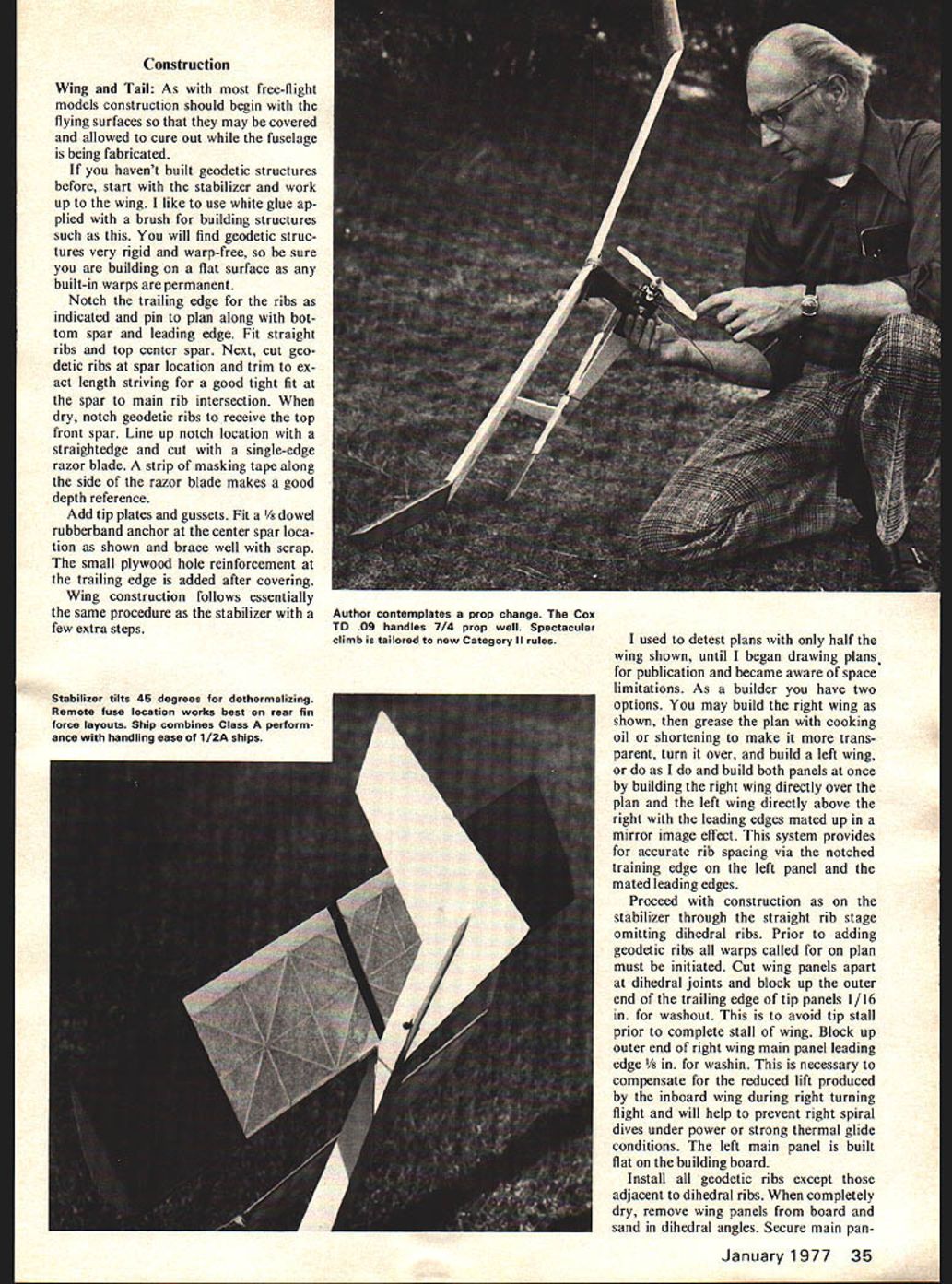
As with free-flight models, construction should begin with the flying surfaces. They may be covered and allowed to cure while the fuselage is being fabricated. If you haven't built geodetic structures before, start the stabilizer work up. Wing building is like any other structure when you use white glue applied with a brush. In building geodetic structures you will find them very rigid and virtually warp-free. Be sure you build on a flat surface — built-in warps are permanent.
Notch trailing-edge ribs as indicated on the plan along the bottom spar and leading edge. Fit straight ribs to the top center spar. Next cut geodetic ribs to spar locations; trim to exact length, striving for a good tight fit at the spar/main rib intersections. Dry-notch the geodetic ribs to receive the top front spar. Line up notch locations; with a straightedge cut with a single-edge razor blade. A strip of masking tape along the side of the razor blade makes a good depth reference. Add tip plates and gussets. Fit a 1/8" dowel rubber-band anchor at the center spar location shown. Brace well with scrap small plywood hole reinforcement. The trailing edge is added after covering. Wing construction follows essentially the same procedure as the stabilizer with a few extra steps.
I used to detest plans showing only half a wing until I began drawing plans and became aware of publication space limitations. As the builder you have two options: you may build the right wing shown directly over the plan (a little grease, cooking oil or shortening will make the plan transparent), then turn it over and build the left wing; or build both panels once by building the right wing directly over the plan with the left wing directly above the right, leading edges mated up for a mirror-image effect. This system provides accurate rib spacing via the notched trailing edge.
Proceed with construction of the stabilizer through the straight-rib stage, omitting the dihedral ribs. Prior to adding the geodetic ribs, the warps called for on the plan must be initiated. Cut the wing panels apart at the dihedral joints. Block up the outer end trailing-edge tip panels 1/16" for washout to avoid tip stall prior to completing the stall wing. Block up the outer end of the right wing main panel leading edge 1/8" washin — necessary to compensate for reduced lift produced by the inboard wing during right-turning flight; this will help prevent right spiral dives under power in strong thermal glide conditions. The left main panel is built flat. Install all geodetic ribs except those adjacent to dihedral ribs. When completely dry, remove wing panels from board and sand in dihedral angles. Secure main pan-
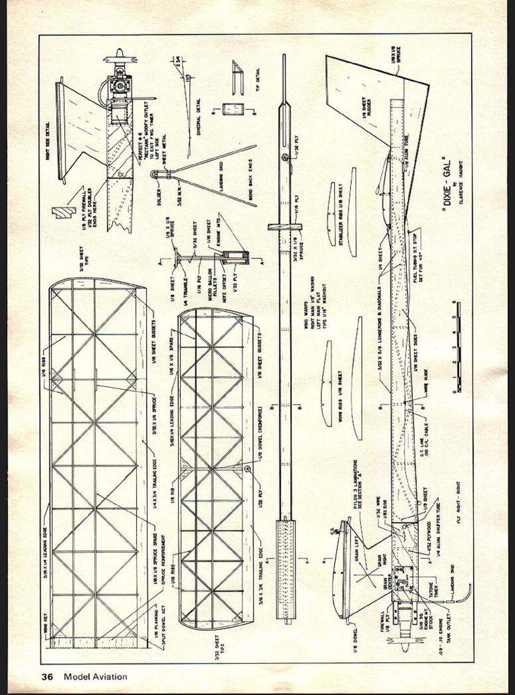
DIXIE - GAL
els to board. Block up tip panels to proper dihedral angle and glue to main panels. When thoroughly dry, join main panels at center in similar manner. Allow to dry, then add dihedral braces and ribs, center rib, geodetic dihedral ribs, center planking and gussets. Notch geodetic ribs and install front spar.
The surfaces are now ready for a thorough sanding. Shape leading edges carefully to maintain airfoil shown on plan. Employ a sanding block long enough to span three or four ribs to insure uniformity. Blend ribs into trailing edge smoothly. Work carefully, taking care not to damage the structures with corners of your sanding block. Dust thoroughly.
Determine at this point what covering material you plan to use. The structure is plenty adequate for plastic films. If you elect to use them, proceed according to the manufacturer's instructions.
I recommend medium Silkspan for wing main panels and Japanese tissue for the wing tips and the stabilizer. Prior to covering with paper, predope perimeters of structures with two coats of dope, sanding after the first coat.
Apply tissue covering, water shrink and apply two coats of clear dope. Cut trim from colored Japanese tissue and your AMA numbers should be applied with thinner at this time. Follow with three more coats of clear dope on the wing and two on the stabilizer.
Set flying surfaces aside to cure, preferably secured by some sort of jig holding fixture to insure alignment.
Fuselage
Before starting fuselage construction, study the plan carefully in order to be thoroughly familiar with the design. Prefabrication of certain parts and subassemblies will aid the overall progress.
Start construction with the pylon. Cut center lamination from 1/16" plywood. Add outer laminations of 3/32" sheet balsa bonded with contact cement. The left balsa lamination ends at the engine mount. Check plan for proper grain direction. You will note that the pylon is offset to the right. This allows the engine thrust line to be centered and the mounts to be bonded directly to the plywood pylon core. Secure 5/16" sq. engine mount stock to the pylon assembly with epoxy. Space to suit width of engine being used. Don't waste time trying to buy 5/16" sq. engine mount stock in a hobby shop. Have a friend with a table saw rip it for you from oak or maple.
Cut longeron and diagonal stock from medium 3/32" sheet. Notch top and bottom for rudder and top for pylon. Glue up light 1/8" stock for rudder and sub-fin assembly. When dry, cut to shape and add 1/16" by 1/8" spruce hard edging. Cut fuselage sides from medium 1/16" sheet. Glue up some medium 1/8" stock for wing rest.
Begin final fuselage assembly by pinning right side to plan. Be sure your building board is flat as any curve will be built right into the fuselage with disastrous results. Install longerons and diagonal bracing. Fill in support in pylon and tank area as shown on plan right side detail. Add pylon engine mount and rudder-sub fin subassemblies. Align 1/8" plywood firewall and secure.
Add fill in structural members to pylon and finally left fuselage side. Let this assembly dry thoroughly, at least overnight. Remove fuselage from board and sand carefully. Secure 1/32" plywood doublers to front of fuselage with contact cement. Check top of pylon for proper incidence angle and install wing rest reinforcing with 1/4" triangle stock. Wing runners and hold-down dowels complete the pylon. Build up stabilizer rest and install on fuselage. Glide turn will be controlled by stab tilt so I recommend the stab rest be installed with built-in tilt to align the stabilizer with the right main wing panel. This will avoid a lot of unnecessary shimming later.
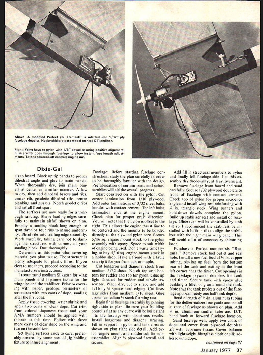
Purchase a Perfect number six "Rectank." Remove stock fuel outlet and seal hole. Install a new fuel feed of 1/8"-in. copper tubing, picking up fuel from the bottom rear of the tank and exiting at the front left corner near the timer. Cut openings in the fuselage plywood doublers for tank and timer. Secure tank with epoxy glue building a fillet of glue around the tank. Note that the tank projects out of the fuselage approximately one half tank depth.
Bend a length of 1/8" aluminum tubing for the de-thermalizer line guide and install at rear of fuselage as shown on plan. Add 1/4" aluminum snuffer tube and D.T. band hook at forward fuselage location.
Sand fuselage well, apply two coats of dope and cover from plywood doublers aft with Japanese tissue. Cover balance with lightweight fiberglass cloth or silk adhered with dope.
Dixie-Gal/Haught
continued from page 37
Apply two more coats of dope and add microballoon fillets around base of pylon if desired. Continue with finish and trim until desired effect is achieved.
Fabricate landing skid from 3/32 music wire and install on fuselage. Make up D.T. line from control-line cable. Rig a stop using a short piece of fuel tubing tied in D.T. line to bear against aluminum tube line guide at rear of fuselage. A 40-degree stab pop up will bring Dixie-Gal down without damage.
Check alignment of pylon and rudder with straightedge or a taut thread held against the edge of the pylon. If alignment of rudder is not perfect, correct as necessary. Band on wing and align carefully measuring from base of rudder to tips. When satisfied all is square install wing keys.
Mount engine, a 7x4 prop, timer and fuel line. Assemble complete airplane and check C.G. Model should balance 3/4 in. forward of wing trailing edge. Ballast as necessary. Nose weight can be added by securing sheet lead under engine mount screws or within fuselage beneath the timer. Make a final check for specified warps.
At this time it may occur to you, as you view the assembled model, that you may have created a monster. A Half-A size model with twice the normal engine size! You may feel inclined to wear a hard hat and have a pre-dug fox hole near your launch site. Let me assure you none of this will be necessary.
Flight Testing: This may begin with a few hand glides over the legendary tall grass. However I personally have never located this phenomenon. Actually, a couple of tosses to determine that the model is neither diving nor stalling is sufficient. Hand gliding can't really tell you much more as too many variables exist. Glide trim is best worked out after the power pattern is established. Dixie-Gal should be tested at full power using the fuel and prop you plan to use in competition. For the first flight launch at a 60-degree angle slightly to right of wind with right wing down slightly for a three-second engine run. The model should move out smartly maintaining a 60-degree climbing angle and should turn approximately one-quarter turn to the right. Try to remember exactly what happened on each test flight. Transition may or may not be good on such a short engine run as speed will not be built up to normal. Glide at this point should only be safe. Use a 30-second D.T. fuse to avoid extensive chasing. If all is We'll continue to increase engine run in two second increments until nine seconds is reached. Transition should be good by the five-second run and no later than seven seconds. Three-quarters turn in nine seconds is about right. Climb angle will increase as speed builds. More turn will improve transition. Glide should be just above stalling speed on calm days and slightly faster for rough air.
Make all adjustments one at a time and according to the following four basic rules.
Climb Turn—rudder tab
Use 1/16 x 1/8 x 3/4 balsa shaped like trailing edge stock, glue to side of rudder at trailing edge. Pylon models must turn right under power.
Climb Angle—stab incidence
Raise trailing edge to increase. Raise leading edge to decrease. Shim with matchbook cover or plywood 1/32" at a time.
Glide Turn—stab tilt
Model will turn toward high tip. Right tip high for right turn. Should be about even with right main wing panel.
Glide Angle—shift CG
Add lead to tail to slow glide, add lead to nose to increase speed.
The above trim changes will act independently of one another with the exception of the stabilizer tilt. When a shim is placed under one end of the stab rest, it will have the effect of one-half that shim thickness being placed under the stab leading edge center and will reduce climb angle. Removal of stab tilt shims will have the reverse effect and will increase climb angle.
Fly Dixie-Gal often to be thoroughly familiar with her flight characteristics. Enter competition every chance you can. Dixie-Gal has won several trophies for me and can do the same for you.
TIMER!
Transcribed from original scans by AI. Minor OCR errors may remain.

