
Do We Really Understand Our Propellers
The math involved in determining propeller pitch, speed and performance is incomprehensible to many of us. This article spells it all out step-by-step and shows how we can apply it to understanding the props we commonly use. John Brownlee
John Brownlee, 52, has built model aircraft since 1940, and RC since the late 1950s. An engineer, he says he is "interested in aerodynamic theory merely out of curiosity."
MPH = 0.8 × Pitch × RPM × 0.000947 (1)
Introduction
The title of this article stems from the fact that Eq. 1 is widely used to calculate either required propeller pitch or the speed a model will fly based on the nominal propeller pitch and in-flight rpm. As a pitch equation, it identifies the correct nominal pitch for optimum efficiency for propellers with symmetrical airfoil. The airfoil used for the typical model aircraft propeller possesses considerable camber, however, and Eq. 1 does not contain sufficient information to deal with this fact. As a result, it tends to overstate required pitch by 25–35%.
When used to calculate mph, Eq. 1 is justified on the assumption that moving forward at a speed equal to the calculated advance of the nominal pitch line constitutes a condition of 100% efficiency. Actual efficiency, assumed to be about 80%, is construed to serve as a speed limiter relative to the nominal pitch-line advance, hence the 0.8 term in Eq. 1. Neither of these assumptions is correct, however, and it is quite possible to observe a model flying at 1.4 times the speed predicted.
The purposes of this article are to:
- Develop an equation for calculating pitch for optimum efficiency which can accommodate cambered airfoils.
- Analyze the efficiency curve of a propeller with Clark-Y airfoil to demonstrate that optimum efficiency can result when the propeller is moving forward faster than the calculated pitch-line advance speed.
- Develop the correct equation for calculating level flight speed in order to point out the parameters which must be known in order to achieve acceptable accuracy.
J-Factor (Advance Ratio) and Effective Pitch
Normally, propeller performance and power absorption are a function of the J-Factor (or advance ratio), quantitatively J = V / (nD).
- V is the forward velocity in feet per second (1.467 × mph).
- n is the propeller revolutions per second (rpm / 60).
- D is the diameter in feet (d / 12).
Example: If you observed your plane flying at 60 mph on a 10‑in. propeller turning 12,000 rpm, J would be found as follows:
J = (1.467 × 60) / (200 × 0.8333) = 0.528
If we consider the effective pitch, P, of the propeller in the above example, we find it to be:
P = 1056 × mph / rpm
P = 1056 × 60 / 12000 = 5.28 inches
Since the above calculations differ only by the fact that diameter was not considered for P, it follows that:
P = J × D (or P = J × d)
with P having the dimensions assigned to the diameter (feet or inches). Note that P has no relationship whatsoever to the actual propeller nominal pitch and will vary with the restraint imposed on the forward progress.
Now assume that all restraint (drag) were removed from the example propeller and just enough power applied to maintain 12,000 rpm. The propeller would gain speed until it reached a point at which no thrust (lift) could be generated; the efficiency would be zero. Call this point J1. Then P1 = J1 × d.
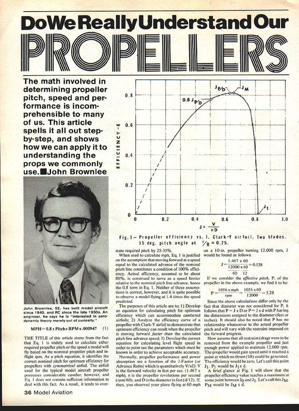
A brief glance at Fig. 1 (see caption below) shows that propeller efficiency reaches a maximum at some point between J0 and J1. Call this JM; PM would be JM × d.
Figure 1 — Propeller efficiency vs. J. Clark‑Y airfoil. Two blades. 15° pitch angle at r/R = 0.75.
In addition to the changeable effective pitch, a fixed‑pitch propeller must also possess an unchangeable nominal pitch. This pitch designation contains the information required to construct the propeller and must, therefore, be the answer to any equation to calculate pitch for efficiency. Call this pitch PN. There is no direct J counterpart to PN, but it can be shown that when J = P/d the propeller will be moving forward at a speed equal to the calculated nominal pitch-line advance speed.
Origin of the 0.8 Term in Eq. 1
Assume you had many curves like Fig. 1 covering propellers with various pitch angles, numbers of blades, airfoils, etc., and by careful scrutiny concluded that when J = 0.8 the propeller efficiencies are so near maximum that any slight deviations can be ignored. You could then say PM = 0.8 P1. This is where the 0.8 in Eq. 1 originates, and it is only a coincidence when the efficiency is 80% at 0.8 P1. For propellers with very low pitch angles, only 92–93% efficiency will be realized.
We may write P1 = 1.25 PM. Substituting our mph target and specified rpm gives:
P1 = 1.25 × 1056 × mph / rpm (1a)
This is Eq. 1 rearranged, and it does not result in a useful answer since PN is not considered. Mathematically, we can divide both sides by PN/P1 without changing the equation. This gives:
PN = 1.25 / (P1 / PN) × 1056 × mph / rpm (2)
Eq. 2 cannot be solved rationally (since PN appears on both sides) without knowing P1 / PN, which is a function of the amount of camber in the airfoil used. In solving Eq. 1 and calling the result PN, you assume that P1 / PN = 1.00, which, for all practical purposes, is true for symmetrical airfoils. From Eq. 2 it can be seen that when P1 / PN = 1.25, optimum efficiency (within the limits imposed by our 0.8 J compromise) will be realized when the propeller is moving forward at the pitch-line advance speed. If P1 / PN is greater than 1.25, optimum efficiency will be realized while the propeller is "outrunning its pitch."
Effect of Camber — Clark‑Y Example
Look at Fig. 1 in detail to see what the camber of a Clark‑Y airfoil does to the P1 / PN ratio. This curve was purloined from an old aerodynamic treatise and is applicable to models because the pitch angle at 0.75R is in the range commonly used. J1 is about 0.82, so for a diameter of 11 inches, P1 would be:
P1 = J1 × d = 0.82 × 11 = 9.02 inches
PN is found as follows:
PN = tan(pitch angle) × π × d × (r/R) = 0.268 × 3.14 × 11 × 0.75 = 6.94 inches (3)
P1 / PN = 9.02 / 6.94 = 1.30, so we know that the propeller will be running 1.30 / 1.25 = 1.04 times as fast as its nominal pitch-line at J = 0.8. Since 1.04 is only 4% faster, the difference is small. You can further see that at J = 0.70, or 0.70 / 0.63 = 1.10 times the nominal pitch-line advance speed, the propeller is still converting about 80% of the power required to turn it into thrust.
Is 1.30 the correct value of P1 / PN to use in Eq. 2? While it is preferable to use the actual value, it changes with P1/d and blade thickness ratio. For a 16 × 4, P1 / PN will be about 1.37; for a 9 × 7, it will be about 1.25. Many propellers have blades thinner than the Clark‑Y (11.6%), and this automatically reduces camber, hence P1 / PN. As we shall see later, performance will not be affected critically by pitch as long as the diameter is correct to let the engine develop its maximum power, so for computation purposes a value of 1.25 is suggested. Results obtained using Eq. 2 will be no better than the mph value used, which leads into purpose number three.
Calculating Level Flight Speed
The starting point is the equilibrium condition where available thrust equals total airframe drag. In engineering terms:
Efficiency, E = Power Out / Power In = (Thrust × Velocity) / (550 × hp) (4)
therefore,
Thrust, T = 550 × hp × E / V (4a)
Total drag, D = C_D × 0.00119 × V^2 × S (5)
where:
- C_D is airframe drag coefficient based on wing area,
- V is velocity in feet per second,
- S is wing area in square feet.
Equating Eq. 4a to Eq. 5 and solving for V gives:
Vmph = 52.7 × sqrt(hp × E / (C_D × S)) (6)
From Eq. 6 you must know:
- the hp your propeller is absorbing (the effective power output of your engine), and
- the approximate efficiency the propeller can attain at the indicated V.
The latter will vary substantially with P/D: a 16 × 4 being capable of only about 67% maximum, a 9 × 7 being able to reach about 85% maximum. C_D will vary greatly depending on the type of aircraft involved. It can be as low as 0.025 and up to probably as high as 0.075 for a heavy, slow‑flying biplane with a flat cowl and lots of rigging, wires, struts, wire‑spoked wheels, etc. S should be easy to determine.
The point of all this is to illustrate how much detailed information is needed to calculate flight speed accurately. Obviously, if you get close by multiplying pitch × rpm × efficiency, it will be an accident of the painless type. Eq. 6 can, however, be used to accurately quantify the effect of changing one of the parameters involved while leaving the others fixed.
Example
Suppose we observed our 11 × 6.94 propeller in flight so that P1 = 0.8 PN and we had a real good power plant turning it at 15,000 rpm at the time. J would be 0.8 × 0.63 = 0.504, and the actual V would be about 115 ft/s or 78.4 mph. From Fig. 1 we can determine that E would be about 0.77.
Recognizing that the propeller is operating at a higher‑than‑optimum angle of attack, we wish to change propellers so that P = PN. As pitch is reduced, diameter must be increased to preserve hp, with the net effect that J will also decrease to about 0.45. Fig. 1 will no longer be valid since the pitch angle will be reduced, and the new efficiency curve will be somewhat to the left of the curve of Fig. 1. E at J = 0.45 will be about 0.80, and the new V will be:
Vnew = sqrt(0.80 / 0.77) × 78.4 ≈ 1.013 × 78.4 = 79.4 mph.
A slight further increase in V would result from reduced slipstream velocity. Such a small change would only be justified by the desire to squeeze the last drop of performance out of the powerplant (engine plus propeller).
Conclusion
Propellers are more complicated than exciting. With cambered airfoils, Eq. 1 overstates required pitch unless camber effects (P1 / PN) are accounted for. Accurate speed predictions require knowledge of engine hp, propeller efficiency at the operating J, airframe drag coefficient and wing area. With the relationships and equations presented here, you should be able to assess propeller behavior more rationally and, when asked the question in the title, respond with a definite "yes."
Transcribed from original scans by AI. Minor OCR errors may remain.

