
Focke-Wulf 190D
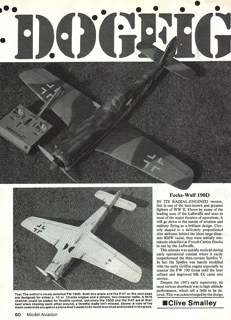
IN ITS RADIAL-ENGINED version, the Focke-Wulf 190 is one of the best-known and greatest fighters of WWII. Flown by many leading Luftwaffe aces and used in most major theaters of operations, it is remembered as a brilliant design. Cleverly shaped with a slim, delicately proportioned airframe behind the blunt large-diameter BMW radial, early examples were mistakenly identified as French Curtiss Hawks in Luftwaffe service.
This mistake was soon corrected during early combat, where the FW 190 easily outperformed the contemporary Spitfire V. The Spitfire was hastily modified with an early Griffon engine to counter the FW 190 threat until the improved Mk IX became available.
Despite the 190's early superiority, its serious drawback was high-altitude performance. The design team acknowledged this even before the plane entered service and redesigned the airframe for an inline engine. Three versions were developed: FW 190B, C and D. The D version, fitted with the Junkers Jumo inline engine, proved the best; the B and C types were quickly abandoned.
Incorporating an annular radiator in the nose of the 190D, the appearance still suggested a radial installation, but inline-type exhausts gave the conversion away. The inline engine was longer than the radial, so the increase in nose length was compensated by inserting an additional fuselage bay just in front of the fin. The wing layout remained essentially the same.
Scale model overview
The increased nose length of the D version led me to model it in small size as shown in the plans. In retrospect the model was initially nose-heavy, so the radial-engine version would be satisfactory for a small model if the radio gear is properly placed.
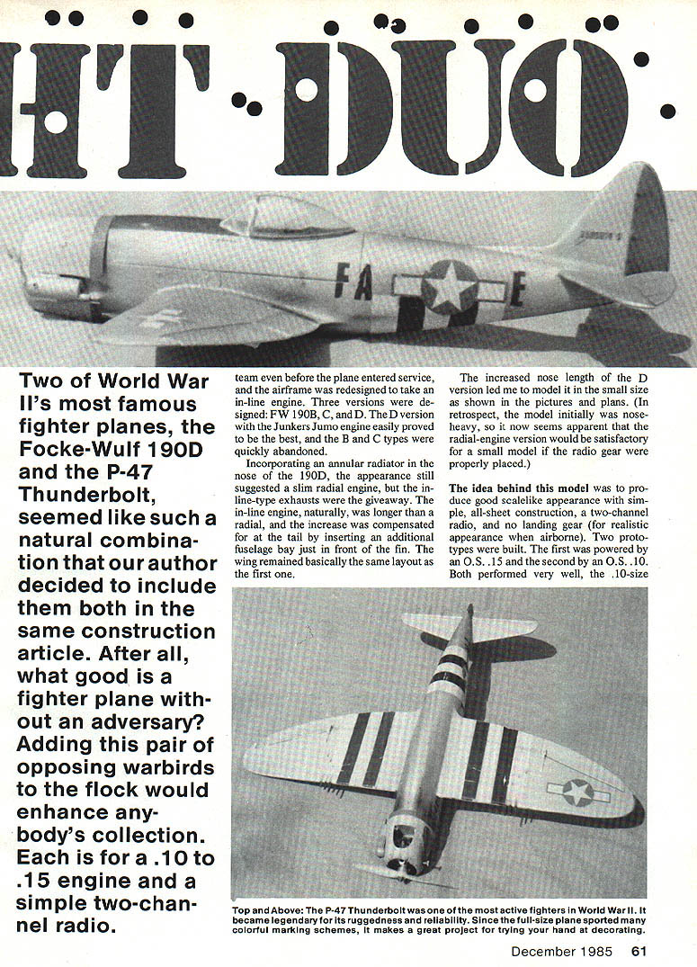
The idea behind this model was to produce a good scale-like appearance with simple all-sheet construction, two-channel radio, and no landing gear (for realistic appearance when airborne). Two prototypes were built: the first powered by an O.S. .15 and the second by an O.S. .10. Both performed well; the .10 provided adequate power. Model flying weight was about 2 lb.
The greatest thrills with these small models are low-level runs, moderately close rolling go-pasts, and pulling up into a combat climb. With micro-sized airborne radio equipment, a third channel could be used for throttle control, but neither prototype's throttle control seemed worth the extra weight and complexity.
Construction sequence (general)
Construction sequence on a one-piece model is important — little of the fuselage can be completed before assembling wing and tail surfaces. Build in the sequential order given here.
Tail surfaces
- Cut tail surfaces and stabilizer/elevators from sheet balsa and sand smooth.
- Use a cut-down commercial elevator horn to allow internal connection; adjustments can be made at the servo end.
- Build the vertical fin and rudder separately for better scale effect. The fin is built over the skin sides; though it has an unusual section, no problems should be encountered.
- Omit the block leading-edge part until after fuselage assembly. Round off the rudder leading edge and glue the fin in place.
Wing
- The wing is built atop the bottom skin. Cut the 1/16" sheet skin to the outline on the plans, including the wing-tip block.
- Mark spar and rib positions on the sheet and pin it down flat.
- Glue the main spar in position followed by the leading edge and aileron leading-edge pieces.
- Carefully mark the ailerons and cut them away from the wing. Round the leading edge of the ailerons for adequate movement and cut the hinge slots.
- Epoxy-glue the aileron torque rods at the same time you hinge the ailerons.
- Join the wing panels and cut out the top skins to clear the servos; you may complete the servo linkage at this time. Finally, remove the servo and sand the wing smooth all over.
Note: At this scale and flight speed, a pronounced rolling motion can result from unequal washout. Ensure washout is equal in each panel.
Fuselage
- Assemble the sides, doublers, and formers F1 to F9. Add strip keel pieces.
- Spot-cement hatch formers H1 to H4 in position, followed by the crutch and keel pieces.
- Fit F10, followed by F4a and F5a.
- If using Ny-Rod-type cable for the elevator, install it now. Epoxy the stabilizer in position and hook up the control cable or pushrod.
- Epoxy the fuselage assembly to the wing structure, checking squareness in all directions.
- Plank the fuselage deck, hatch, and under-nose area; sheet the rear underside.
- Epoxy the fin to the stabilizer and add the sheet leading edge to the fin together with the upper rear fuselage block. Carve and sand to give a continuous flowing curve between the fuselage decking and the fin leading edge. Sand overall to a smooth finish.
- Cut away the spot-cementing to release the hatch. Fiberglass the inside of the lower nose area with lightweight glass cloth and resin.
Engine mount, cockpit and fillets
- Use a commercial engine mount, drilling holes as needed for fuel tubing.
- The engine can be mounted at any angle to accommodate the muffler used.
- Paint the cockpit interior, add a pilot figure, and glue on the canopy.
- Make the wing fillets from 1/16" sheet and card stock.
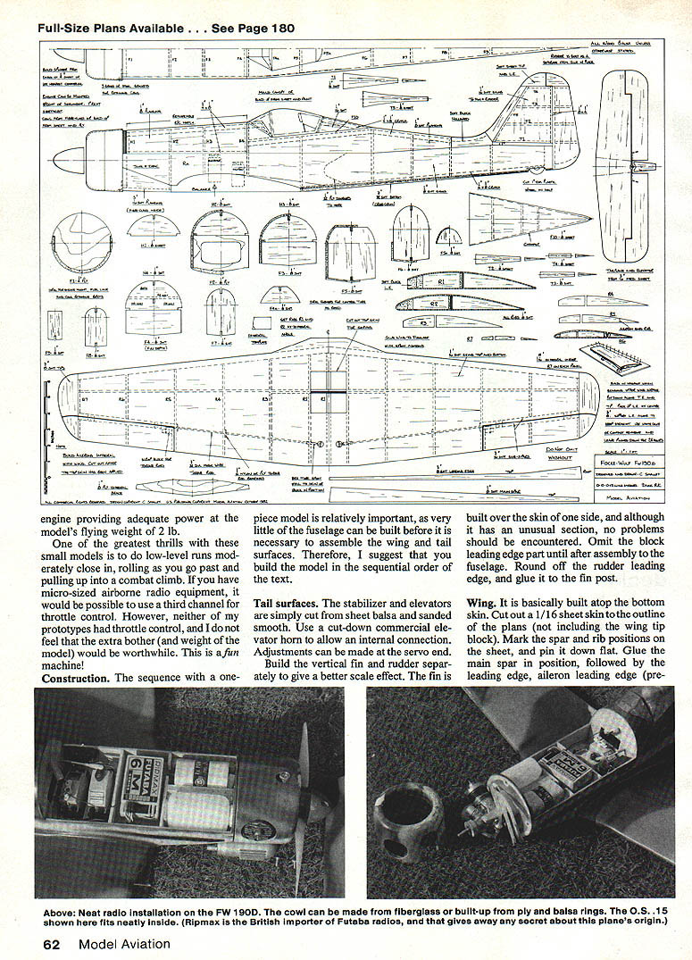
Cowl
- The cowl can be made of fiberglass (preferred for strength) or built-up from plywood and balsa rings.
- Set cowl flaps slightly open to allow cooling air to exit the engine compartment.
- Reference sources can provide information for detailing dummy exhaust stacks and other cowl details.
Covering and finishing
- Plastic film may be used, but the author prefers dope-and-tissue.
- Apply two coats of sanding sealer, sanding between each coat, then dope on lightweight tissue.
- Paint with a matte-finish enamel or dope and fuel-proof it. A clear matte polyurethane gives a realistic finish.
- Fit the engine and RC gear—and your FW 190D is ready for 'combat.'
Flying
- The most difficult part for this small model is the initial hand launch. A helper is preferable for test flights so you can concentrate on controls.
- If built square, free of warps, with equal washout and the CG per the plans, no undue difficulty should arise.
- Although a .10 engine provides sufficient power, a hand launch is a commitment; a sick engine at launch could be disastrous.
- With a two-channel radio, landings are dead-stick. When the tank is nearly dry, gain altitude to plan and line up your approach — you only have one chance. Do not attempt to stretch the glide; that can stall the model. Keep adequate airspeed.
- Keep flying relatively close to the transmitter; otherwise the model becomes very small and can be lost visually.
- Other than these precautions, the model is great fun to fly and very rewarding to see airborne.
References (FW 190)
- Kookaburra: FW 190 Parts 1 and 2.
- Aero Books, Vol. 18: FW 190.
- Profiles No. 3, 94.
- Squadron/Signal Vol. 19: FW 190.
- Harleyford: FW 190 — A Famous German Fighter.
- War Planes of the Third Reich.
- M.A.P. (Aero Modeller) Plan Packs: FW 190A.
- Various books on Luftwaffe camouflage and markings by Kookaburra, Ries, Monogram, etc.
- FW 190 Manual.
- Scale Models magazine: FW 190A.
Dogfight Duo / Smalley
Continued from page 157
Here is No. 2 in my series of WWII fighters — a P-47 — accurate in outline as much as possible. The only obvious deviations from scale are the airfoil section and omission of small detailing; these could be included if the builder wishes. As with the FW 190D, three-channel controls could be used (to include throttle), although only two channels (elevator and aileron) were used on the prototype.
Construction of the P-47 is similar to the FW 190D. Wings are much the same except the P-47 uses cable-in-tube aileron controls whereas the FW 190D uses torque rods. The major difference is in the fuselage. There is logic to the building sequence; follow the order given here.
Wing and tail
- Construct the wing over the bottom skin as per the FW 190D. Ensure washout in the wing is equal in each panel — it is vital.
- Tail surfaces can be built up per the plan for a nice scale effect, though time can be saved by cutting the fin, rudder, stabilizer, and elevators from 3/16" sheet balsa.
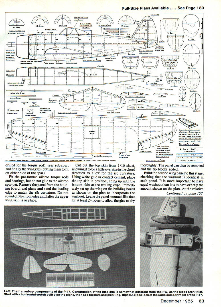
Fuselage
- The P-47 fuselage has no flat side areas, so it starts with a horizontal crutch built over the plan.
- Add half formers to the top and bottom, leaving F5 and F6 full size for now.
- Add wing support saddles, keel members, and a few strips of planking for support.
- Cut away F5 and F6, and epoxy the wing in position.
- Fit the stabilizer supports (F13) and epoxy the horizontal tail in position. Fit and glue the fin/rudder, assuring the elevator horn has necessary clearance.
- Glue on the belly block, but do not carve it until planking is complete.
- Plank or sheet the fuselage using precurved strips (wetted on the outside or doped on the inside). Carve and sand the belly block to match the planking, and sand everything smooth.
- Fit the engine mount, hatch retainers, servo mounts, canopy, etc.
Cowl, finishing and flying
- The comments and suggestions for cowl construction, finishing, and flying given for the FW 190D apply equally to the P-47.
- The prototype P-47 model weighed 1 lb. 15 oz. and used an O.S. .15 for power.
References (P-47)
- Kookaburra: P-47 Parts 1 and 2.
- P-47 in Action, Squadron/Signal.
- Aces of the Eighth.
- Aces of the Ninth, Twelfth, and Fifteenth Air Forces.
- Ninth Air Force History.
- Checkertail Clan.
- Skybird Group.
- Thunderbolt at War.
- Thunderbolt — A Documentary History.
- Morgan P-47.
- Aero Modeller Plan Pack.
- Profiles No. 7, 262.
- Aero Books, No. 6: P-47.
These models — both the FW 190D and the P-47 — are great fun to fly with a minimum outlay of time and cash. P-47 pilots, remember: Beware of that FW 190 in the sun!
Transcribed from original scans by AI. Minor OCR errors may remain.

