
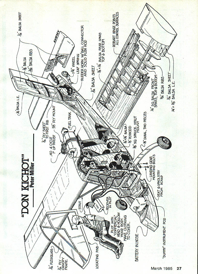
Don Kichot
Peter Miller
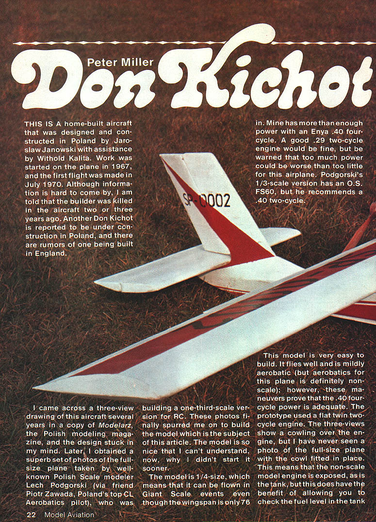
THIS IS a home-built aircraft that was designed and constructed in Poland by Jaroslaw Janowski with assistance from Witold Kalita. Work was started on the plane in 1967, and the first flight was made in July 1970. Although information is hard to come by, I am told that the builder was killed in the aircraft two or three years ago. Another Don Kichot is reported to be under construction in Poland, and there are rumors of one being built in England.
I came across a three-view drawing of this aircraft several years ago in a copy of Modelarz, the Polish modeling magazine, and the design stuck in my mind. Later, I obtained a superb set of photos of the full-size plane taken by well-known Polish scale modeler Lech Podgorski (via friend Piotr Zawada, Poland's top C/L aerobatics pilot), who was building a one-third-scale version for RC. These photos finally spurred me on to build the model which is the subject of this article. The model is so nice that I can't understand, now, why I didn't start it sooner.
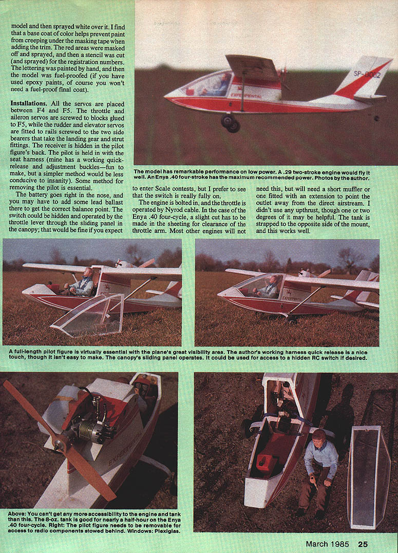
The model is 1/4-size, which means that it can be flown in Giant Scale events even though the wingspan is only 76 in. Mine has more than enough power with an Enya .40 four-cycle. A good .29 two-cycle engine would be fine, but be warned that too much power could be worse than too little for this airplane. Podgorski's 1/3-scale version has an O.S. FS60, but he recommends a .40 two-cycle.
This model is very easy to build. It flies well and is mildly aerobatic (but aerobatics for this plane is definitely non-scale); however, these maneuvers prove that the .40 four-cycle power is adequate. The prototype used a flat twin two-cycle engine. The three-views show a cowling over the engine, but I have never seen a photo of the full-size plane with the cowl fitted in place. This means that the non-scale model engine is exposed, as is the tank, which does have the benefit of allowing you to check the fuel level during a slow, low flypast.
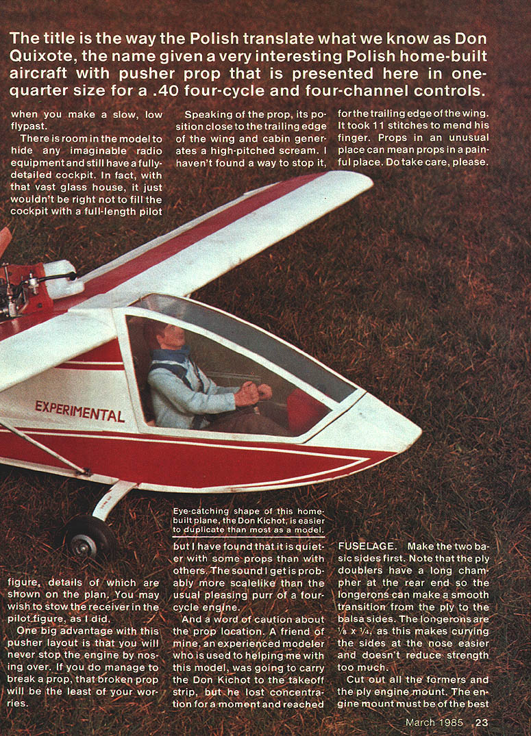
There is room in the model to hide any imaginable radio equipment and still have a fully detailed cockpit. In fact, with that vast glass house, it just wouldn't be right not to fill the cockpit with a full-length pilot figure, details of which are shown on the plan. You may wish to stow the receiver in the pilot figure, as I did.
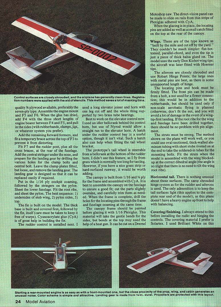
One big advantage with this pusher layout is that you will never stop the engine by nosing over. If you do manage to break a prop, that broken prop will be the least of your worries.
Speaking of the prop, its position close to the trailing edge of the wing and cabin generates a high-pitched scream. I haven't found a way to stop it, but I have found that it is quieter with some props than with others. The sound I get is probably more scalelike than the usual pleasing purr of a four-cycle engine.
And a word of caution about the prop location. A friend of mine, an experienced modeler who is used to helping me with this model, was going to carry the Don Kichot to the takeoff strip, but he lost concentration for a moment and reached for the trailing edge of the wing. It took 11 stitches to mend his finger. Props in an unusual place can mean props in a painful place. Do take care, please.
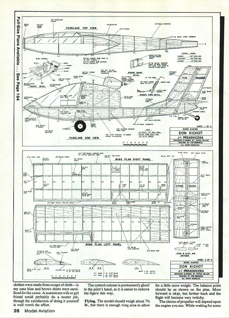
FUSELAGE
Make the two balsa sides first. Note that the ply doublers have a long chamfer at the rear so the longerons can make a smooth transition from the ply to the balsa sides. The longerons are 1/8 x 1/4, as this makes curving the sides at the nose easier and doesn't reduce strength too much.
Cut out all the formers and the ply engine mount. The engine mount must be of the best quality 3/8 plywood available, preferably the seven-ply type. Assemble the engine mount and F5 and F6. When the glue has dried, add F4 with the three short lengths of engine bearer between F4 and F5, and pull in the sides with rubber bands, clamps, jigs, or whatever system you prefer.
Add the remaining forward formers, and fit a temporary brace across the top of F3 to prevent it from distorting.
Fit F7 and the rudder post, plus all the cross braces, at the rear of the fuselage. Add the central stringer under the nose, and prepare for the landing gear by drilling the various holes for the clamp bolts and central bolt. Leave the clamp plates fitted but loose, and remove the landing gear. The landing gear is designed so that it can be replaced easily if required.
Put in the 1/16 ply cockpit coaming, followed by the stringers on the pylon. Sheet the lower fuselage. Fit the root ribs, and sheet the pylon. The best sequence:
- undersides of stub wing
- pylon sides
- top
The fin is built on the model. The thick base is built and covered first, followed by the fin itself; care must be taken to keep it free of warps. Cyanoacrylate glue (CyA) is of great help in building the fin.
The rudder control is installed next. I used a long elevator joiner and horn with one leg cut off and the whole thing supported by two brass tube bearings.
Best to work on the elevator control now. I used an idler bellcrank behind the control horn, but use of Nyrod would allow a straight run to the elevator horn. A hatch under the rudder control bay is a useful option, though it isn't vital. Such a hatch also can help when fitting the tail wheel bracket.
The prototype's tail wheel is steerable from a bellcrank at the bottom of the rudder horn. I didn't use this feature, as I fly from grass which is normally too long for taxiing. However, if you have a nice grass strip or hard-surfaced runway, it would be worth adding.
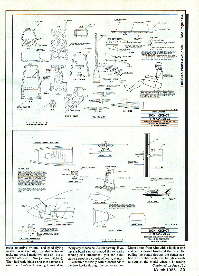
The canopy is built from 1/16 and 1/8 ply for the frame and assembled with CyA. It is best to assemble the canopy on the fuselage to ensure a good fit; cut the parts slightly oversize, and carefully trim them as needed. When the frame is complete, drill the holes for the locating pins through the frame and fuselage coaming at the same time.
The canopy frame should be painted before glazing it with 1/16 Plexiglas. This material will take the gentle bends for the sides, but bends at the top may need the help of a heat gun. It can be cut on a Dremel Motoshop saw. The direct-vision panel can be made to slide on rails from thin strips of Plexiglas adhered with CyA.
When the glazing is in place, the locating pins are added as well as a small catch fitted on the top at the rear of the canopy.
Wings
These are of the type known as "built by the mile and cut off by the yard." They couldn't be much simpler: flat-bottomed, parallel-chord, and even the tip is just a piece of thick balsa glued on. The model uses the early Don Kichot wing tips; the aircraft was later fitted with Hoerner tips.
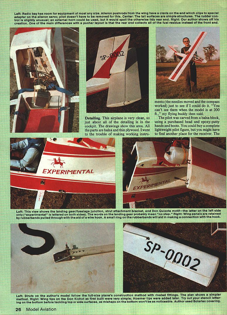
The ailerons are closely shrouded and use Robart Hinge Points; the large ones with metal pins are best, as there is some unsupported length of hinge.
The locating pins and hook must be firmly fitted. The front pin can be made from a bolt, a nut used for a firmer connection; this would be in addition to the rubber bands, but should be used only if non-scale aerobatic flying is planned (otherwise, don't fit the nut, and you will avoid a lot of damage in the event of a wing-tip-first landing). If the root ribs for the wing and fuselage have been drilled together, there should be no problem with pin alignment.
The struts must be strong. The method shown on the plans will work well, or you could also use selected, well-welded aluminium tubing with short studs riveted on at the end to take the soldered-in tubes for the mounting bolts. Fit the struts when the wing is assembled with the wing blocked up at the correct dihedral angle (the angle is so slight that there is no need to tilt the wing root ribs).
Horizontal tail
There is nothing unusual about these surfaces. The same shrouded hinge system as for the rudder and ailerons is used. The only admonition is to keep the tail surfaces light (this applies to the complete rear end of the model), as this plane doesn't have a heavy engine up front to help with balancing.
Covering/finishing
I always attend to this before installing the radio and hinging the controls. The covering material I prefer is Solartex. I used Brilliant White on this.
Installations
All the servos are placed between F4 and F5. The throttle and aileron servos are screwed to blocks glued to F5, while the rudder and elevator servos are fitted to rails screwed to the two side bearers that take the landing gear and strut fittings. The receiver is hidden in the pilot figure's back. The pilot is held in with the seat harness; mine has a working quick-release and adjustment buckles—fun to make, but a simpler method would be less conducive to insanity. Some method for removing the pilot is essential.
The battery goes right in the nose, and you may have to add some lead ballast there to get the correct balance point. The switch could be hidden and operated by the throttle lever through the sliding panel in the canopy; that would be fine if you expect to enter scale contests, but I prefer to see that the switch is really fully on.
The engine is bolted in, and the throttle is operated by Nyrod cable. In the case of the Enya .40 four-cycle, a slight cut has to be made in the sheeting for clearance of the throttle arm. Most other engines will not need this, but will need a short muffler or one fitted with an extension to point the outlet away from the direct airstream. I didn't use any upthrust, though one or two degrees of it may be helpful. The tank is strapped to the opposite side of the mount, and this works well.
Detailing
This airplane is very clean, so just about all of the detailing is in the cockpit. The drawings show this area. All the parts are balsa and thin plywood. I went to the trouble of making working instruments (the needles moved and the compass worked) just to see if I could do it. "You can't see them when the model is at 200 ft.," my flying buddy then said.
The pilot was carved from a balsa block, using a purchased head and epoxy-putty hands and boots. You could buy a complete lightweight pilot figure, but you might have to find another place for the receiver. The clothes were made from scraps of clothing. In my case blue and brown shirts were sacrificed. My seamstress-wife/girlfriend could probably do a neater job, though the satisfaction of doing it yourself is well worth the effort. The control column is permanently glued in the pilot's hand — it is easier to remove the figure this way.
The flying model should weigh about 7 lb., with enough wing area to allow a little extra weight. The balance point is shown on the plan; forward is OK. If it is farther back the flight will become very twitchy. The choice of propeller will depend upon the engine used.
While waiting for some props to arrive in the mail and with a good flying-weather forecast, I decided to try to make my own. I made two 11-5 and two 11-6 props, approximately pitched, with wide blades and thin sections. I used the 11-5 and never got around to trying the other sizes. Just passing on a tip: if you have a band saw, a jigsaw and a sanding-disk attachment, you can hand-carve a prop in a couple of hours.
Assemble the wings with rubber bands — put two hooks through the center section. Make a tool: a wire hook on a dowel handle for pulling the bands through the center section. Rubber bands must be tight enough to support the model when it is resting upside-down on the wing tips. A small ring fitted to the rubber bands will help when attaching them to the wing hooks.
When the engine was started at the first flying session, the first thing we noticed was the unusual noise. It may be caused by the shape of the prop, the nearness of the prop to the trailing edge of the wing, or both. The sound is unique, and it will attract attention regardless of what other plane is flying at the time.
The Enya .40 four-cycle likes 15% nitro fuel, but it will fly on 5%, though it won't have quite the same speed and zip. I found this out when I used 5% by mistake and wondered why the performance had dropped off so much; however, I was still able to stunt the model.
The model is stable in flight once it has been trimmed out. I found that the best trim was with the elevator up so that the top of the horizontal tail looked flat (like an inverted right section), but start with a neutral elevator and allow for plenty of trim.
The Don Kichot model has a characteristic that is found on all very-high-thrust-line models and full-size aircraft. If the throttle is retarded quickly, the model will rear up; if it is advanced rapidly, it will pitch nose-down. In either case the trim returns to normal as soon as the speed has stabilized at the new throttle setting, so correction is best made with the elevator control stick. If the throttle is moved slowly, this pitching is not noticeable. At no time is the pitching a real problem, except it is worth remembering that if you are on a very low, slow pass, you will land if you quickly advance the throttle.
Neither the full-size prototype nor the model are intended to be aerobatic. However, I know that few modelers can resist a little bit of extrovert flying, so the model has been tested with a few maneuvers. The model will loop quite well, though a little extra speed helps. It will do a reasonable slow roll, and it will roll off the top of a loop. Stall turns are really nice and positive. Spins are easy, and recovery is immediate on release of the controls. Negative-G maneuvers should not be attempted, as there is serious risk of the wings pulling out.
This model is easy to build, unusual to see in flight and on the ground, and a true-to-scale model that does not require a truck for hauling, will not rupture you if you pick it up, does not need a degree in aeronautical engineering to build, and will fly for up to a half-hour on 8 oz. of fuel. What else is there to say?
Transcribed from original scans by AI. Minor OCR errors may remain.

