
Dornier Arrow
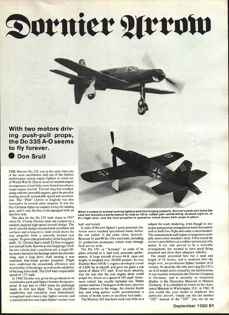
THE Dornier Do 335 was one of the most unorthodox and highest-performance piston-engine fighters of World War II. Its novel tandem engine (push-pull) arrangement gave it little more frontal area than a single-engine aircraft; the resulting low drag combined with two powerful engines produced remarkable speed and acceleration. Nicknamed the "Pfeil" (Arrow) and sometimes called the "Anteater" by pilots, the Do 335 was also the first German fighter to use tricycle landing gear and the first to be equipped with an ejection seat.
Design and development
- The Do 335 concept began in 1937 when Dr. Claude Dornier patented a tandem-engined high-speed aircraft design featuring cruciform tail surfaces and a long drive shaft to drive a rear pusher propeller from a centrally located rear engine.
- To prove the long drive shaft concept, Dornier built a small 22-ft‑span test aircraft, the Göppinger Go 9. The Go 9 had a single 80-hp motor buried in the fuselage below the shoulder wing and a long drive shaft turning a rear-mounted four-blade pusher propeller. Flight tests confirmed the design's efficiency and the drive shaft's reliability; the Go 9 reached about 137 mph.
- In 1942 Dornier received approval for a push-pull fighter-bomber design, and the prototype first flew in late 1943. Heavy day-fighter and specialized two-seat night-fighter versions were developed and tested.
- Production was limited: between 35 and 40 Do 335s were built, including 21 production prototypes that underwent field service tests.
- The only surviving Do 335 is an A‑0 model owned by the Smithsonian; it was restored by Dornier in Germany and displayed at the Deutsches Museum in Munich. It was scheduled to return to the National Air and Space Museum, Washington, D.C., in 1983. (To duplicate that particular aircraft on a model, use tail number "102" instead of "107".)
Performance and armament
- Wingspan: over 44 ft
- Empty/loaded weight: over 20,000 lb (large aircraft)
- Engines: two Daimler‑Benz 603 E‑1 engines; total about 3,600 hp at takeoff
- Speed: top speed about 475 mph; the rear engine alone could propel the Arrow to about 350 mph
- Armament (varied by version): typically one 30 mm cannon and two 15 mm guns in the nose, plus two 30 mm cannons in the wings
- Payload: internal bomb bay and wing pylons for bombs or auxiliary fuel tanks
Modeling the Do 335
The Do 335 has been little used as a subject for scale modeling, despite lines and arrangement that suit both free-flight and radio-control models. The push-pull engine layout tends to deter many modelers.
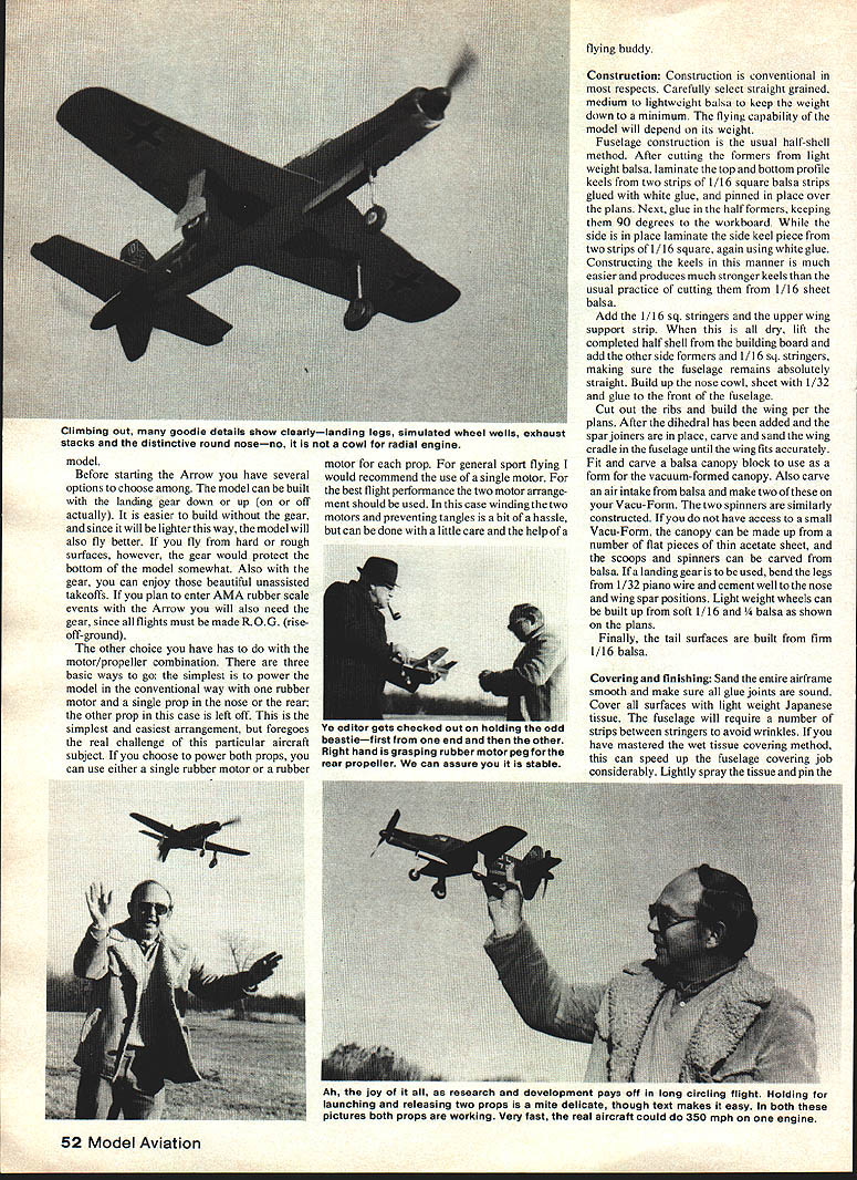
The profile model presented here is rubber-powered, has an 18‑inch span and length, and is modeled after the single-seat pre-production fighter-bomber A‑0 version.
Options before building
- Landing gear:
- Build with landing gear up (no gear): easier, lighter, generally better flying performance.
- Build with landing gear down: protects the bottom on hard/rough surfaces and allows realistic, unassisted takeoffs. Required for AMA rubber-scale events (flights must be R.O.G. — rise-off-ground).
- Motor/propeller arrangement:
- Single motor, single prop (either nose or rear). Simpler but not fully faithful to the prototype.
- Single motor driving both props. Good compromise.
- Two motors, two props. Best flight performance but requires care winding and preventing tangles; a flying buddy helps.
Construction
Construction is conventional. Select straight‑grained, medium to lightweight balsa to keep weight down — flying capability depends strongly on weight.
- Fuselage
- Use the half‑shell method. Cut formers from lightweight balsa.
- Laminate the top and bottom profile keels from two strips of 1/16" square balsa glued with white glue and pinned over the plans.
- Glue in the half formers, keeping them 90° to the workboard.
- While the side is in place, laminate the side keel from two strips of 1/16" square balsa with white glue.
- Add 1/16" sq. stringers and the upper wing support strip.
- When dry, lift the half shell from the board, add the other side formers and 1/16" sq. stringers, keeping the fuselage absolutely straight.
- Build up the nose cowl, sheet with 1/32" balsa and glue to the front of the fuselage.
- Wing
- Cut ribs and build the wing per the plans.
- After adding dihedral and installing spars and joiners, carve and sand the wing cradle in the fuselage until the wing fits accurately.
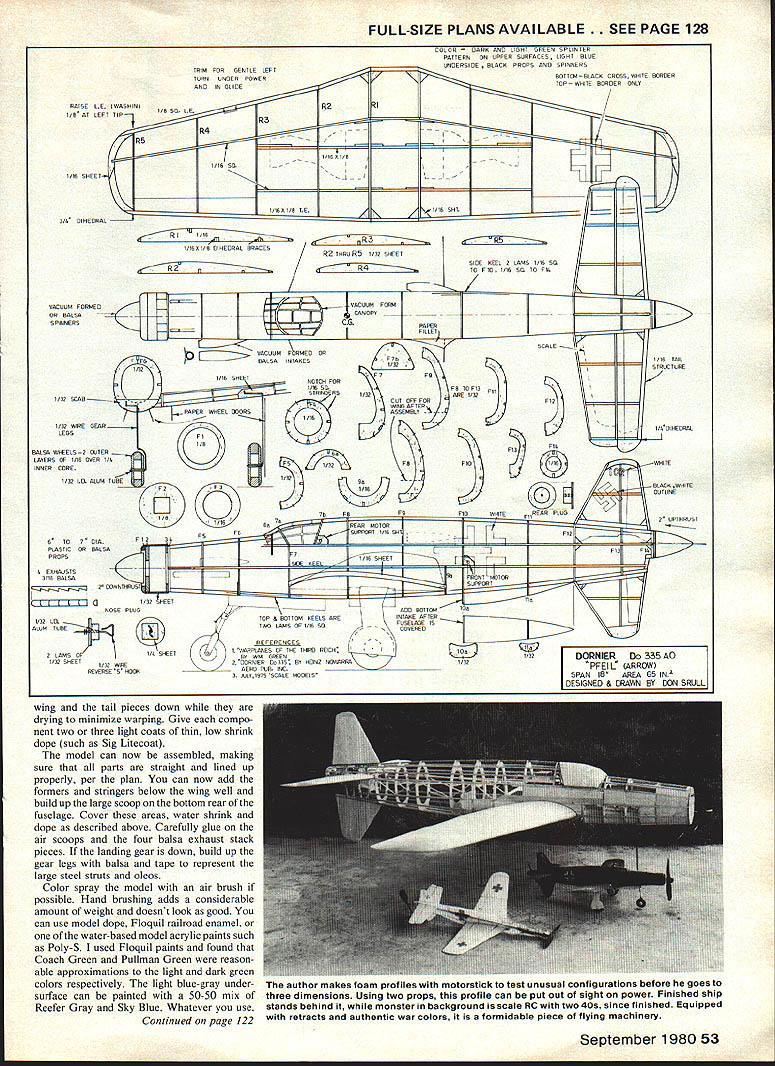
- The left wing panel should have about 1/8" wash-in (i.e., the leading edge at the tip raised about 1/8") to correct for the thrust and prop effects; correct any warps or misalignment before test flying.
- Canopy, scoops and spinners
- Carve and sand a balsa canopy block as a form for a vacuum-formed canopy.
- Carve an air intake from balsa and make two on a vacu‑form. The two spinners are constructed similarly.
- If no vacu‑form is available, form the canopy from flat pieces of thin acetate and carve scoops and spinners from balsa.
- Landing gear and wheels
- If using gear, bend legs from 1/32" piano wire and cement well to the nose and wing spar positions.
- Light‑weight wheels can be built up from soft 1/16" and 1/4" balsa as shown on the plans.
- If the landing gear is down, build up the gear legs with balsa and tape to represent large steel struts and oleos.
- Tail surfaces
- Build tail surfaces from firm 1/16" balsa.
Covering and finishing
- Sand the entire airframe smooth and ensure all glue joints are sound.
- Cover all surfaces with lightweight Japanese tissue. The fuselage will require several strips between stringers to avoid wrinkles.
- If you use the wet tissue method, lightly spray the tissue and pin it to the formers; this speeds covering and reduces wrinkles.
- Assemble the model, making sure all parts are straight and properly aligned per the plan.
- Add formers and stringers below the wing well and build up the large scoop on the bottom rear of the fuselage. Cover these areas, water‑shrink and dope as required.
- Carefully glue on the air scoops and the four balsa exhaust‑stack pieces.
- Color: spray with an airbrush if possible (hand brushing adds weight and is less attractive). Use model dope, Floquil railroad enamel, or water‑based model acrylics (e.g., Poly‑S).
- Suggested Floquil approximations: Coach Green and Pullman Green for light and dark greens; a 50/50 mix of Reefer Gray and Sky Blue for the light blue‑gray undersurface.
Flying and trim
- Install a loop (or loops) of 1/8" rubber, about 1–6 in. long, for initial test flights.
- Before winding, set about 2° downthrust in both props. For the rear prop this means the shaft should be angled slightly upward toward the top of the fuselage (i.e., producing downthrust).
- Start with about 150 turns in the motor(s). Make sure the rear‑prop motor is wound in the proper direction.
- Launching technique:
- Launching can be tricky because of the lower fin and rear prop. The recommended method is to grasp the model by both spinners — front in the left hand, rear in the right. Release the front prop first and then gently push the model forward with the right hand. A few practice launches will make this routine reliable.
- Flight trimming:
- Under low power the model should descend in a long powered glide with a very slight left turn. Adjust the tail surfaces until you get this flight path; avoid changing the thrust setting or the CG at this stage.
- After successful flights, increase windings by about 100–150 turns at a time. Once you exceed about 500 turns, use thrust adjustments only to achieve a smooth, slow climb and cruise to the left followed by a slow left descent.
- If built and adjusted as described, the model should have pleasing looks and good flying ability. A scaled-up version of about 24‑in. span could offer spectacular performance and accommodate more scale detail. Who will be the first to try?
Transcribed from original scans by AI. Minor OCR errors may remain.

