
Double Duty
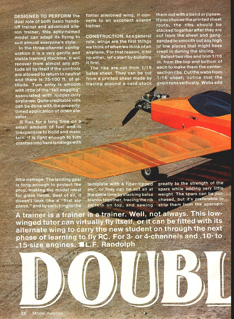
Designed to perform the dual role of both a basic hands-off trainer and an advanced aileron trainer, this aptly-named model can adapt its flying to suit almost everyone's style.
In the three-channel configuration it is a very gentle and stable training machine. It will recover from almost any attitude all by itself if the controls are allowed to return to neutral and there is 75–100 ft. of altitude. Turn entry is smooth with little of the "tail wagging" associated with rudder-only airplanes. Quite creditable rolls can be done with the properly timed application of down elevator.
It flies for a long time on a small amount of fuel and is inexpensive to build and maintain. It is light enough to turn crashes into hard landings with little damage. The landing gear is long enough to protect the prop, making the model ideal for grass fields. Best of all, it doesn't look like a "first airplane," and by switching to the flatter aileroned wing, it converts to an excellent aileron trainer.
A trainer is a trainer is a trainer. Well, not always. This low-winged tutor can virtually fly itself, or it can be fitted with its alternate wing to carry the new student on through the next phase of learning to fly RC. For 3- or 4-channels and .10- to .15-size engines. — L.F. Randolph
Construction
Wings are the first things we'll build.
- Ribs: Cut from 1/16-in. balsa sheet. You can cut them from a printed sheet by tracing around a card-stock template with a fiber-tipped pen, or cut many at once by stacking blanks, tracing the rib pattern on top, and sawing them out with a band or jig saw. If you use a printed sheet, stack the cut ribs and gang-sand to smooth any irregularities.
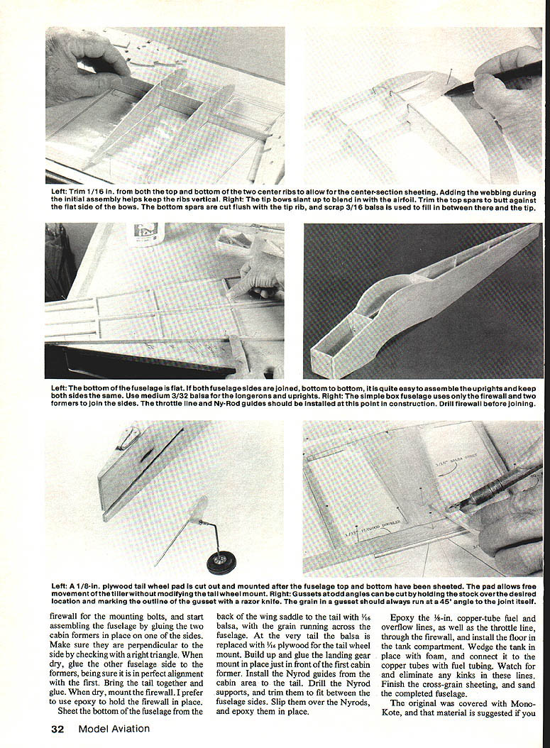
- Center-section ribs: Select two ribs and trim 1/16 in. from the top and bottom of each to make them the center-section ribs.
- Webs: Cut from 1/16-in. sheet with the grain running vertically. Webs add strength to the spars while adding very little weight.
- Spars: Can be purchased, but it's preferable to strip them from the appropriate stock. Use AB-grain stock—10-lb. wood for the main spars and 8-lb. for the other spars.
Cover the plan with wax paper and begin building the center section first. Pin the bottom main spar in place on the plan, slip some ribs onto the spar, and use them to trim the webs to the proper angle so the ribs will be slanted for the dihedral. Adding webbing during initial assembly helps keep ribs vertical.
When all ribs and webs are installed, add the top main spar. Make sure it is glued to all the webs as well as to the ribs. The front top spar can be installed at this time, but do not add the top trailing-edge sheet yet; install it after the wings are joined at the dihedral joints. Build the other two panels the same way, with the angled ribs at opposite ends.
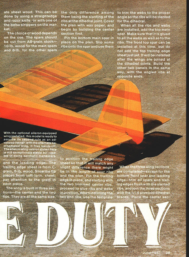
The wing is built in three sections—the center and the two tips. They are all the same size. To position the trailing-edge sheet so it will match any slight differences in rib length, pin the trailing edge in place and, starting with the two trimmed center ribs, proceed to glue ribs and webs in position. When installing the two end ribs, use the template to position the trailing-edge sheet so it will match any slight differences there might be in your ribs and the plan.
When the three wing sections are completed (except for the bottom front spar and leading edge), trim all spars and trailing edges flush with the slanted ribs, and join the three sections with 1/16-in. plywood dihedral braces. Place the center section between the spars and sand the completed wing. On a flat bench, elevate the outboard ends of the two tip sections to match the angled ribs; using a sharp razor, slice 1/16 in. from the joined ribs at the side of the main spars, fit the plywood dihedral braces, check fit, and glue joints. When everything is dry, install the bottom front spar and leading edge. Glue the two tip ribs and note the slant upward as they become flush with the top-spar stubs. Use scrap spar material to fill between the bottom main spars at the tips. Sheet the center section between the spars and sand.
Trailing-edge sheet: Use C-grain, 1/8-in. wood. Since the tip pieces are from soft 1/8-in. sheet, pay attention to grain direction in each piece.
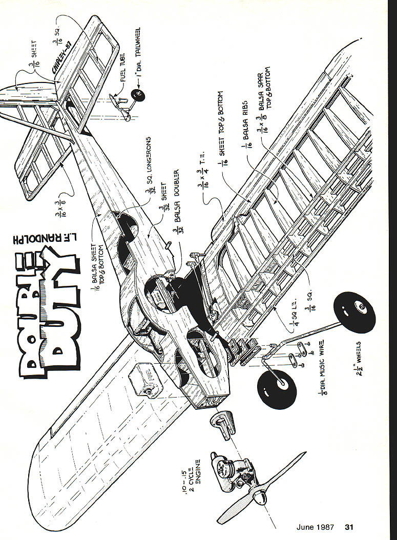
Stabilizer and rudder: Built right over the plan just as the wing. Install two 1/2-in. plywood spar doublers for added strength. The plan shows 3/16-in. sq. hardwood for the elevator carry-through; a 5/16-in. dowel will work as well. Join mating surfaces and sand outlines to match.
Fuselage
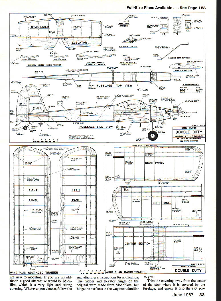
The fuselage sides are cut from medium (8-lb.) 3/32-in. balsa sheet. Do not cut the wing saddle into the sides until after the doublers are glued in place. The doublers are also 3/32-in. balsa—hard stock—laid at a 45° angle to the grain of the sides. When the doublers are cemented in place, pin the two sides together and sand them to the same outline with a sanding block and 100-grit sandpaper. While still pinned together, cut the wing saddle and drill the 1/4-in. holes for the wing-mounting dowels.
Separate the sides and add 3/32-in.-sq. longerons and uprights as well as servo- and tank-mounting rails. Cut out and drill the firewall and the two cabin formers; epoxy T-nuts on the back side of the firewall.
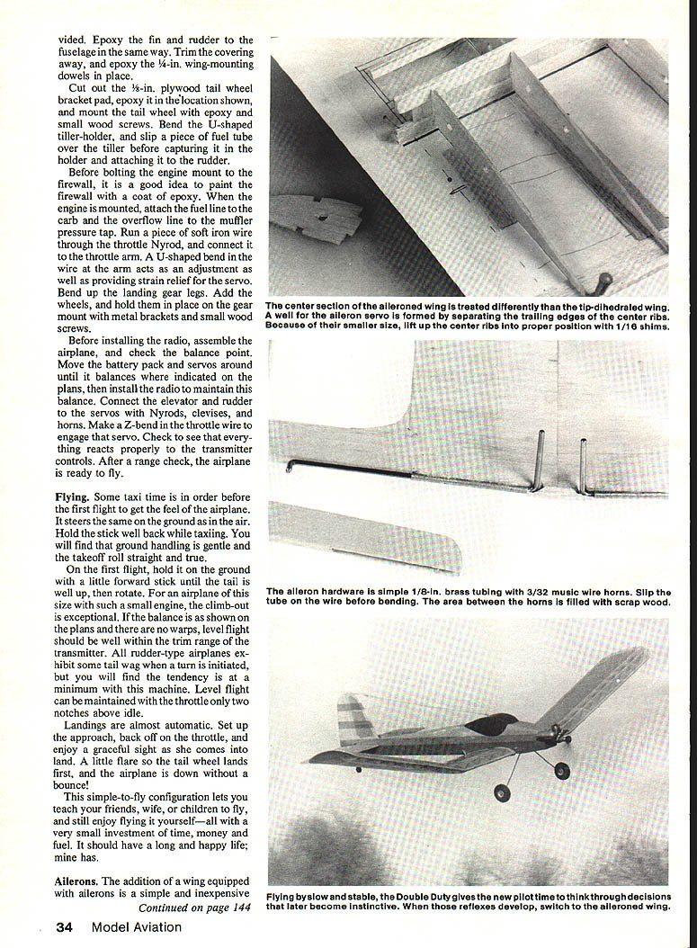
Gussets of odd angles can be cut by holding stock over the desired location, marking the outline, and cutting with a razor knife. The grain of the gusset should always run at a 45° angle to the joint.
Start assembling the fuselage by gluing the two cabin formers in place on one side. Make sure the sides are perpendicular by checking with a right triangle. Dry-glue the other fuselage formers, being sure of perfect alignment before final glue. Bring the tail together, glue, and dry-mount the firewall; epoxy is recommended to hold the firewall in place.
Sheet the bottom of the fuselage from the back of the wing saddle to the tail with 1/16-in. balsa, with the grain running across the fuselage. Where the tail balsa is very thin, replace it with 1/16-in. plywood for the tail-wheel mount. Build up and glue the landing-gear mount in place just forward of the first cabin former.
Install Nyrod guides in the cabin area. Drill the Nyrod supports and trim them to fit between the fuselage sides. Slip the Nyrods in and epoxy them in place.
Epoxy the copper-tube fuel and overflow lines, as well as the throttle line, through the firewall. Install the floor of the tank compartment, wedge the tank in place with foam, and connect the copper tubes to the fuel tubing. Watch for and eliminate any kinks in these lines. Finish the cross-grain sheeting, and sand the completed fuselage.
Install the tailwheel spring and retainer, mount the tailwheel assembly and control horn. Balance the airplane as shown on the plan, and add lead to the nose if necessary. Install the radio gear and engine, check control throws, and perform a range check before the first flight.
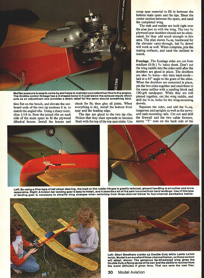
Using tiller-type tail-wheel steering greatly reduces the load on the rudder hinges and gives smoother, more responsive ground handling. A torsion-bar landing gear is easy to install and absorbs some of the shock incurred in hard landings; use this type of landing gear if necessary—it also simplifies wing changes when switching from a three-channel trainer to a four-channel aerobatics trainer.
A muffler-pressure tank helps maintain constant fuel flow to the engine. The throttle-control linkage should have a U-shaped bend just below the exhaust stack that acts as an adjustment and provides strain relief should the servo bind.
Before bolting the engine mount to the firewall, paint the firewall with a coat of epoxy. When the engine is mounted, attach the fuel line to the carb and the overflow line to the muffler pressure tap. Run a piece of soft iron wire through the throttle Nyrod and connect it to the throttle arm. A U-shaped bend in the wire at the arm acts as an adjustment and provides strain relief for the servo. Bend up the landing gear legs, add the wheels, and hold them in place on the gear mount with metal brackets and small wood screws.
Before installing the radio, assemble the airplane and check the balance point. Move the battery pack and servos until it balances where indicated on the plans, then install the radio to maintain this balance. Connect the elevator and rudder to the servos with Nyrods, clevises, and horns. Make a Z-bend in the throttle wire to engage that servo. Check that everything reacts properly to the transmitter controls. After a range check, the airplane is ready to fly.
Cut out the 1/8-in. plywood tail-wheel bracket pad, epoxy it in the location shown on the plan, and mount the tailwheel with epoxy and small wood screws. Bend the U-shaped tiller holder and slip a piece of fuel tube over the tiller before capturing it in the holder and attaching it to the rudder.
Covering and Final Assembly
The original was covered with MonoKote, and that material is suggested for those new to modeling. If you are an old-timer, a good alternative would be Micafilm, which is very light and strong. Whatever you choose, follow the manufacturer's instructions for application. Hinge the rudder and elevator in the way most familiar to you.
Trim the covering away from the center of the stabilizer where it is covered by the fuselage, and epoxy the stabilizer into the slot protruding in the fuselage when assembling the tail. Epoxy the fin and rudder to the fuselage in the same way. Trim the covering away and epoxy the 1/4-in. wing-mounting dowels in place.
Balance the airplane as shown on the plan, install radio gear and engine, check control throws, and perform a range check before the first flight.
Flying
Some taxi time is in order before the first flight to get a feel for the airplane. It steers the same on the ground as in the air. Hold the stick well back while taxiing. Ground handling is gentle and the takeoff roll is typically straight and true.
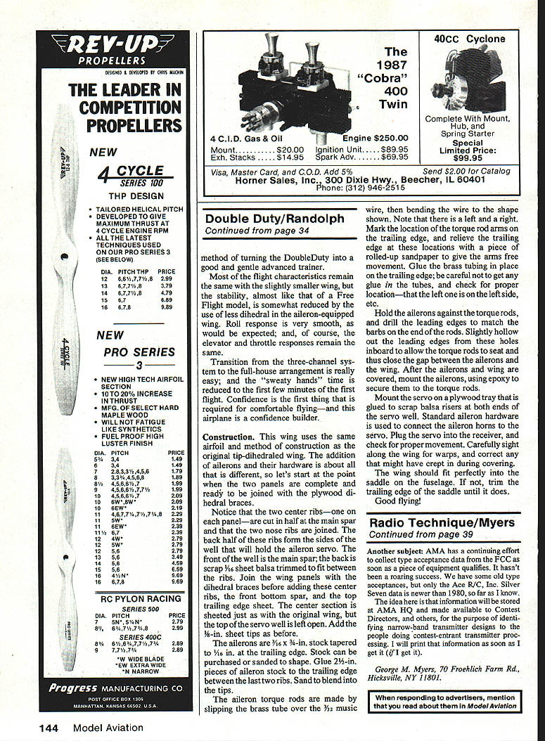
On the first flight, hold it on the ground with a little forward stick until the tail is up, then rotate. For an airplane of this size with such a small engine, climb-out is exceptional. If the balance is as shown on the plans and there are no warps, level flight should be well within the trim range of the transmitter. All rudder-type airplanes exhibit some tail wag when a turn is initiated, but the tendency is minimal with this machine. Level flight can be maintained with the throttle only two notches above idle.
Landings are almost automatic. Set up the approach, back off on the throttle, and enjoy a graceful sight as she comes in to land. A little flare so the tail wheel lands first, and the airplane is down without a bounce!
This simple-to-fly configuration lets you teach friends, family, or children to fly, and still enjoy flying it yourself—all with a very small investment of time, money, and fuel.
Ailerons
The addition of a wing equipped with ailerons is a simple and inexpensive method of turning the Double Duty into a good and gentle advanced trainer.
Most flight characteristics remain the same with the slightly smaller aileron wing, but the stability—almost like that of a Free Flight model—is somewhat reduced due to the use of less dihedral in the aileron-equipped wing. Roll response is very smooth, and elevator and throttle responses remain the same.
Transition from the three-channel system to the full-house arrangement is easy; initial nervousness is usually limited to the first few minutes of the first flight. Confidence is the first thing required for comfortable flying—and this airplane is a confidence builder.
Construction (aileron wing)
This wing uses the same airfoil and construction method as the original tip-dihedraled wing. The addition of ailerons and their hardware is about all that differs.
- Join panels: Start at the point when the two panels are complete and ready to be joined with the plywood dihedral braces.
- Servo well: Notice that the two center ribs—one on each panel—are cut in half at the main spar and the two nose ribs are joined. The back half of these ribs form the sides of the well that will hold the aileron servo. The front of the well is the main spar; the back is scrap 1/16-in. sheet balsa trimmed to fit between the ribs. Join the wing panels with the dihedral braces before adding these center ribs, the front bottom spar, and the top trailing-edge sheeting. The center section is sheeted as with the original wing, but the top of the servo well is left open. Add the 1/16-in. sheet tips.
- Ailerons: Use 3/16 x 3/4-in. stock tapered to 1/16 in. at the trailing edge. Stock can be purchased or sanded to shape. Glue 1/2-in. pieces of aileron stock to the trailing edge between the last two ribs and sand to blend into the tips.
- Torque rods: Make the aileron torque rods by slipping a brass tube over 3/32-in. music wire, then bending the wire to the required shape. There is a left and a right. Mark the location of the torque-rod arms on the trailing edge and relieve the trailing edge at these locations with a piece of rolled-up sandpaper to give the arms free movement. Press the brass tubing in place on the trailing edge—be careful not to get glue in the tubes—and check proper left/right location.
- Aileron fit: Hold the ailerons against the torque rods and drill the aileron leading edges to match the barbs on the ends of the rods. Slightly hollow out the leading edges from these holes inboard to allow the torque rods to seat and thus close the gap between the ailerons and the wing. After covering, mount the ailerons using epoxy to secure them to the torque rods.
- Servo mounting: Mount the servo on a plywood tray glued to scrap balsa risers at both ends of the servo well. Use standard aileron hardware to connect the aileron horns to the servo. Glue the servo in the receiver and check for proper movement.
- Final checks: Carefully check for warps after covering and correct any that might have crept in. The wing should fit perfectly into the saddle on the fuselage; if not, trim the trailing edge of the saddle until it does.
Good flying!
Transcribed from original scans by AI. Minor OCR errors may remain.

