
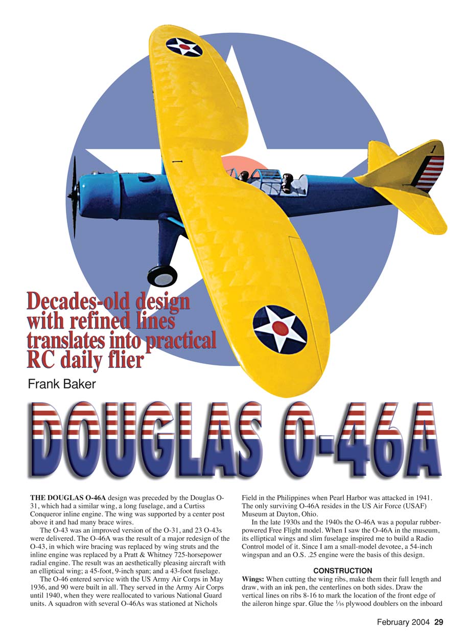
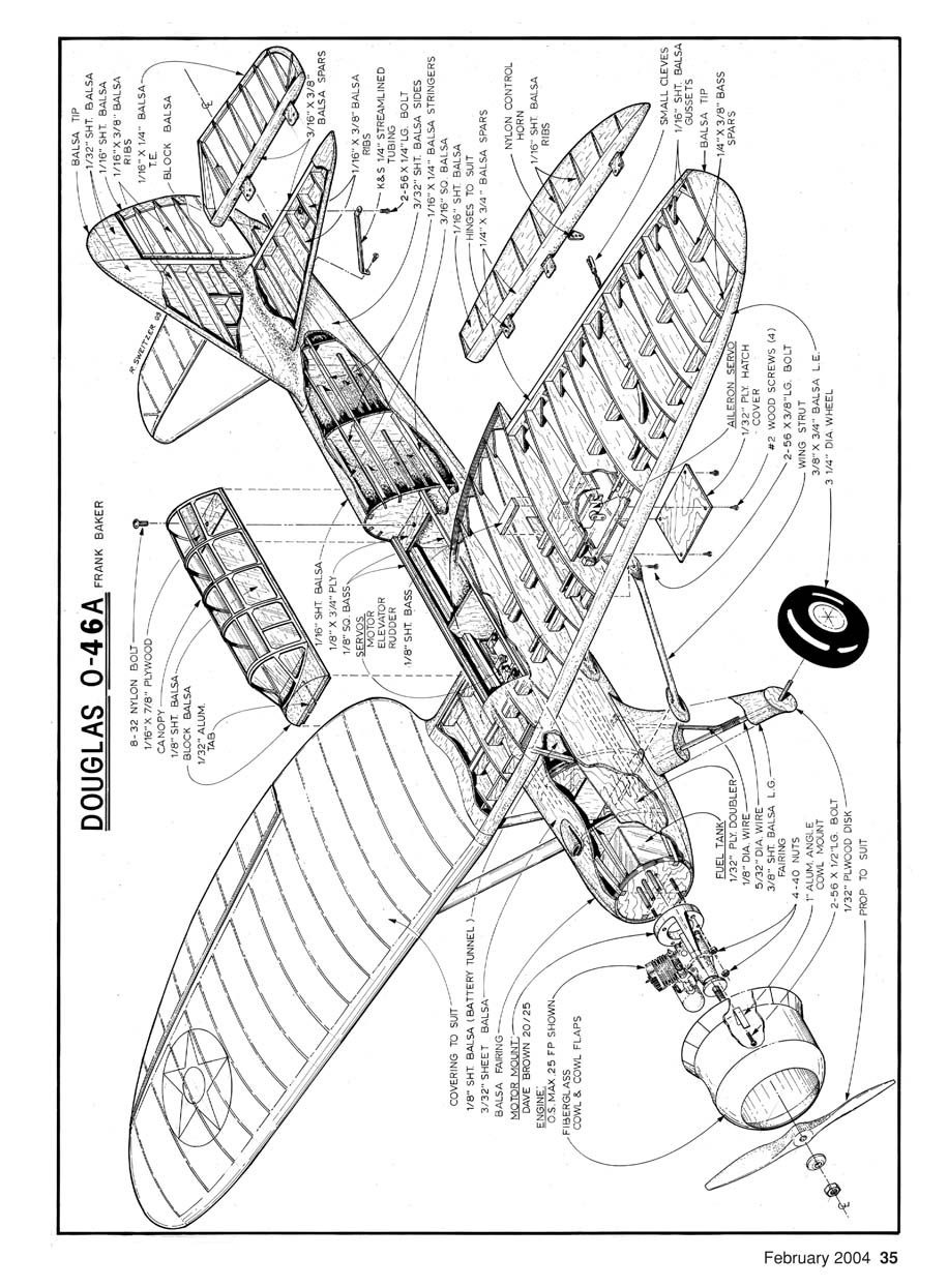
Douglas O-46A
Decades-old design with refined lines translates into practical RC daily flier
Frank Baker
DOUGLAS O-46A
#### History The Douglas O-46A design was preceded by the Douglas O-31, which had a similar wing, a long fuselage, and a Curtiss Conqueror inline engine. The wing was supported by a center post above it and had many brace wires.
The O-43 was an improved version of the O-31; 23 O-43s were delivered. The O-46A was the result of a major redesign of the O-43, in which wire bracing was replaced by wing struts and the inline engine was replaced by a Pratt & Whitney 725-horsepower radial engine. The result was an aesthetically pleasing aircraft with an elliptical wing, a 45 ft 9 in span, and a 43 ft fuselage.
The O-46 entered service with the US Army Air Corps in May 1936; 90 were built in all. They served in the Army Air Corps until 1940, when they were reallocated to various National Guard units. A squadron with several O-46As was stationed at Nichols Field in the Philippines when Pearl Harbor was attacked in 1941. The only surviving O-46A resides in the USAF Museum at Dayton, Ohio.
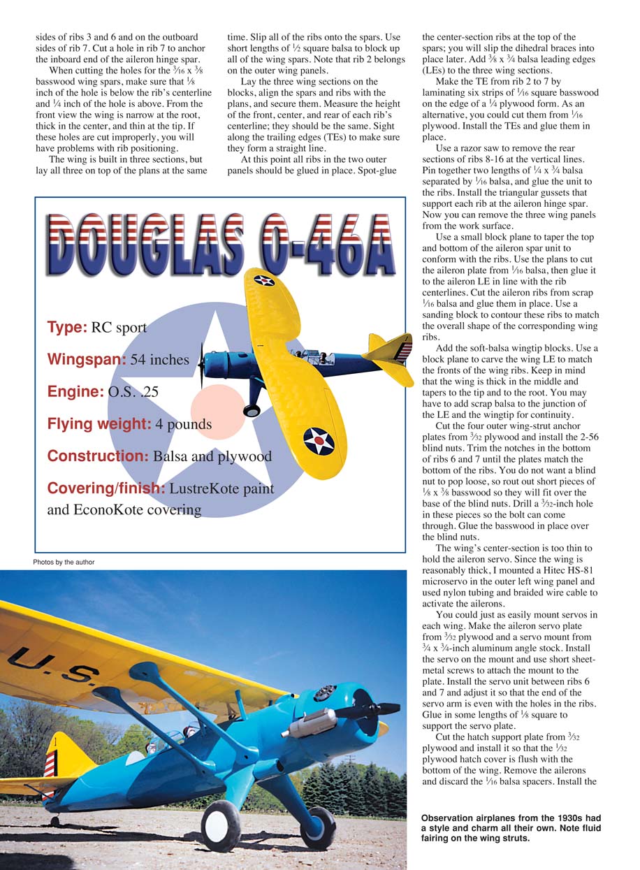
In the late 1930s and the 1940s the O-46A was a popular rubber-powered free-flight model. When I saw the O-46A in the museum, its elliptical wings and slim fuselage inspired me to build a radio-control model of it. Since I am a small-model devotee, a 54-inch wingspan and an O.S. .25 engine were the basis of this design.
Construction
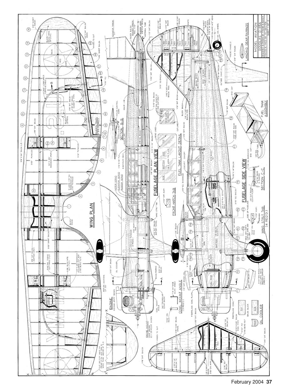
Wings
- When cutting the wing ribs, make them their full length and draw the centerlines on both sides with an ink pen. Draw the vertical lines on ribs 8–16 to mark the location of the front edge of the aileron hinge spar.
- Glue 1/16-inch plywood doublers on the inboard sides of ribs 3 and 6 and on the outboard side of rib 7. Cut a hole in rib 7 to anchor the inboard end of the aileron hinge spar.
- When cutting the holes for the 3/16 x 3/8-inch basswood wing spars, make sure that 1/8 inch of the hole is below the rib centerline and 1/4 inch is above. From the front view the wing is narrow at the root, thick in the center, and thin at the tip. If these holes are cut improperly you will have problems with rib positioning.
- The wing is built in three sections; lay all three on top of the plans at the same time. Slip all of the ribs onto the spars. Use short lengths of 1/2-inch square balsa to block up all of the wing spars. Note that rib 2 belongs on the outer wing panels.
- Lay the three wing sections on the blocks, align the spars and ribs with the plans, and secure them. Measure the height of the front, center, and rear of each rib centerline; they should be the same. Sight along the trailing edges (TEs) to make sure they form a straight line.
- At this point all ribs in the two outer panels should be glued in place. Spot-glue the center-section ribs at the top of the spars; you will slip the dihedral braces into place later.
- Add 3/8 x 3/4-inch balsa leading edges (LEs) to the three wing sections. Make the TE from rib 2 to 7 by laminating six strips of 1/16-inch square basswood on the edge of a 1/4-inch plywood form; alternatively, cut them from 1/16-inch plywood. Install the TEs and glue them in place.
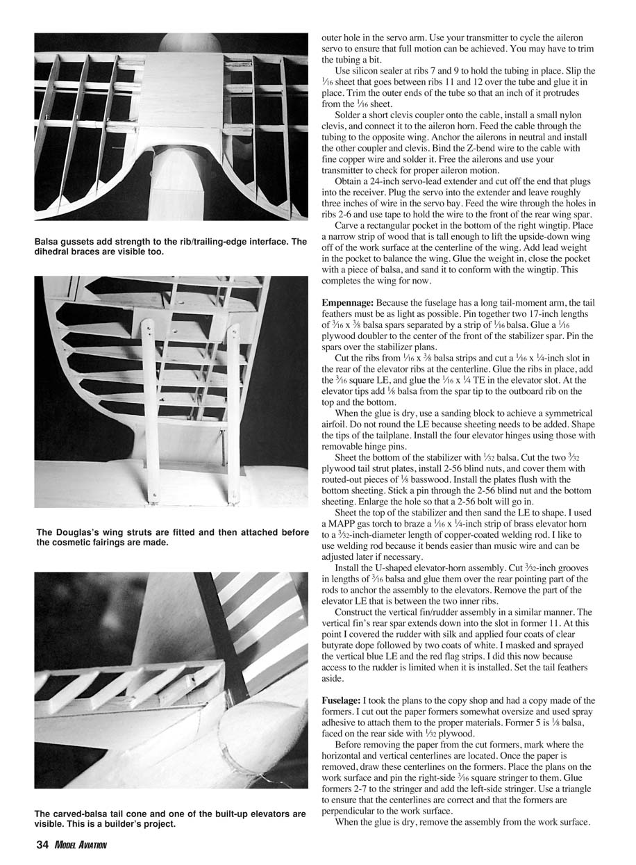
- Use a razor saw to remove the rear sections of ribs 8–16 at the vertical lines. Pin together two lengths of 1/4 x 3/4-inch balsa separated by 1/16-inch balsa, and glue the unit to the ribs. Install the triangular gussets that support each rib at the aileron hinge spar.
- Remove the three wing panels from the work surface. Use a small block plane to taper the top and bottom of the aileron spar unit to conform with the ribs.
- Use the plans to cut the aileron plate from 1/16-inch balsa, then glue it to the aileron LE in line with the rib centerlines. Cut the aileron ribs from scrap 1/16-inch balsa and glue them in place. Use a sanding block to contour these ribs to match the overall shape of the corresponding wing ribs.
- Add soft-balsa wingtip blocks. Use a block plane to carve the wing LE to match the front of the wing ribs. Keep in mind that the wing is thick in the middle and tapers to the tip and to the root. You may have to add scrap balsa to the junction of the LE and the wingtip for continuity.
- Cut the four outer wing-strut anchor plates from 3/32-inch plywood and install the 2-56 blind nuts. Trim the notches in the bottom of ribs 6 and 7 until the plates match the bottom of the ribs. To prevent a blind nut from popping loose, rout out short pieces of 1/8 x 3/8-inch basswood so they will fit over the base of the blind nuts. Drill a 3/32-inch hole in these pieces so the bolt can come through, and glue the basswood in place over the blind nuts.
- The wing's center section is too thin to hold the aileron servo. Since the wing is reasonably thick, I mounted a Hitec HS-81 microservo in the outer left wing panel and used nylon tubing and braided wire cable to activate the ailerons. You could equally mount servos in each wing.
- Make the aileron servo plate from 3/32-inch plywood and a servo mount from 3/4 x 3/4-inch aluminum angle stock. Install the servo on the mount and use short sheet-metal screws to attach the mount to the plate. Install the servo cutout between ribs 6 and 7 and adjust it so that the end of the servo arm is even with the holes in the ribs. Glue in some lengths of 1/8-inch square to support the servo plate.
- Cut the hatch support plate from 3/32-inch plywood and install it so that the 1/32-inch plywood hatch cover is flush with the bottom of the wing.
- Remove the ailerons and discard the 1/16-inch balsa spacers. Install three aileron hinges—with removable pins—at the centerline of the aileron spar. You should be able to get roughly 45° of up and down aileron throw. Attach a small nylon horn to a 1/16-inch plywood plate and recess the aileron LE to accept the plate where shown on the plans.
- Glue the four 1/16-inch plywood center-section and 1/8-inch plywood dihedral braces in place. Put the 1/2-inch square blocks under the center-section spars and anchor the center section over the plans. Slip the outer panels onto the center section. The dihedral should be 1 1/8 inches, measured from the bottom of the spars at rib 2 to the bottom of the spars at rib 16. Use blocks to support the outer panels in the correct position.
- Use slow-drying epoxy to attach the outer wing panels and sight along the spars to ensure that they form a straight line from wingtip to wingtip. Measure the rib centerline heights to make sure there is no twist to the outer wing panels.
- Once the glue is dry, thread nylon tubing from rib 12 on the left wing to rib 12 on the right wing. Make sure that the tubing extends beyond the aileron LE. In the servo bay, remove approximately two inches of tubing to provide for servo arm motion. Make a Z bend in 1/16-inch-diameter wire and insert it into the outer hole in the servo arm. Use your transmitter to cycle the aileron servo to ensure full motion; trim the tubing if necessary.
- Use silicone sealer at ribs 7 and 9 to hold the tubing in place. Slip the 1/16-inch sheet that goes between ribs 11 and 12 over the tube and glue it in place. Trim the outer ends of the tube so that an inch of it protrudes from the 1/16-inch sheet.
- Solder a short clevis coupler onto the cable, install a small nylon clevis, and connect it to the aileron horn. Feed the cable through the tubing to the opposite wing. Anchor the ailerons in neutral and install the other coupler and clevis. Bind the Z-bend wire to the cable with fine copper wire and solder it. Free the ailerons and use your transmitter to check for proper aileron motion.
- Obtain a 24-inch servo-lead extender and cut off the end that plugs into the receiver. Plug the servo into the extender and leave roughly three inches of wire in the servo bay. Feed the wire through the holes in ribs 2–6 and use tape to hold the wire to the front of the rear wing spar.
- Carve a rectangular pocket in the bottom of the right wingtip. Place a narrow strip of wood in the pocket that is tall enough to lift the upside-down wing off the work surface at the centerline. Add lead weight in the pocket to balance the wing. Glue the weight in, close the pocket with a piece of balsa, and sand it to conform with the wingtip.
This completes the wing for now.
Empennage
- Because the fuselage has a long tail moment arm, the tail feathers must be as light as possible. Pin together two 17-inch lengths of 3/16 x 3/8-inch balsa spars separated by a strip of 1/16-inch balsa. Glue a 1/16-inch plywood doubler to the center front of the stabilizer spar. Pin the spars over the stabilizer plans.
- Cut the ribs from 1/16 x 3/8-inch balsa strips and cut a 1/16 x 1/4-inch slot in the rear of the elevator ribs at the centerline. Glue the ribs in place, add the 3/16-inch square LE, and glue the 1/16 x 1/4-inch TE in the elevator slot. At the elevator tips add 1/8-inch balsa from the spar tip to the outboard rib on the top and bottom.
- When the glue is dry, use a sanding block to achieve a symmetrical airfoil. Do not round the LE because sheeting needs to be added. Shape the tips of the tailplane. Install the four elevator hinges using those with removable hinge pins.
- Sheet the bottom of the stabilizer with 1/32-inch balsa. Cut two 3/32-inch plywood tail strut plates, install 2-56 blind nuts, and cover them with routed-out pieces of 1/8-inch basswood. Install the plates flush with the bottom sheeting. Stick a pin through the 2-56 blind nut and the bottom sheeting; enlarge the hole so a 2-56 bolt will go in.
- Sheet the top of the stabilizer and then sand the LE to shape. I used a MAPP gas torch to braze a 1/16 x 1/4-inch strip of brass elevator horn to a 1/32-inch-diameter length of copper-coated welding rod. Welding rod bends easier than music wire and can be adjusted later if necessary.
- Install the U-shaped elevator-horn assembly. Cut 3/32-inch grooves in lengths of 3/16-inch balsa and glue them over the rear pointing part of the rods to anchor the assembly to the elevators. Remove the part of the elevator LE that is between the two inner ribs.
- Construct the vertical fin/rudder assembly in a similar manner. The vertical fin's rear spar extends down into the slot in former 11.
- At this point I covered the rudder with silk and applied four coats of clear butyrate dope followed by two coats of color. I masked and sprayed the vertical blue LE and the red flag strips. I did this now because access to the rudder is limited when it is installed. Set the tail feathers aside.
Fuselage
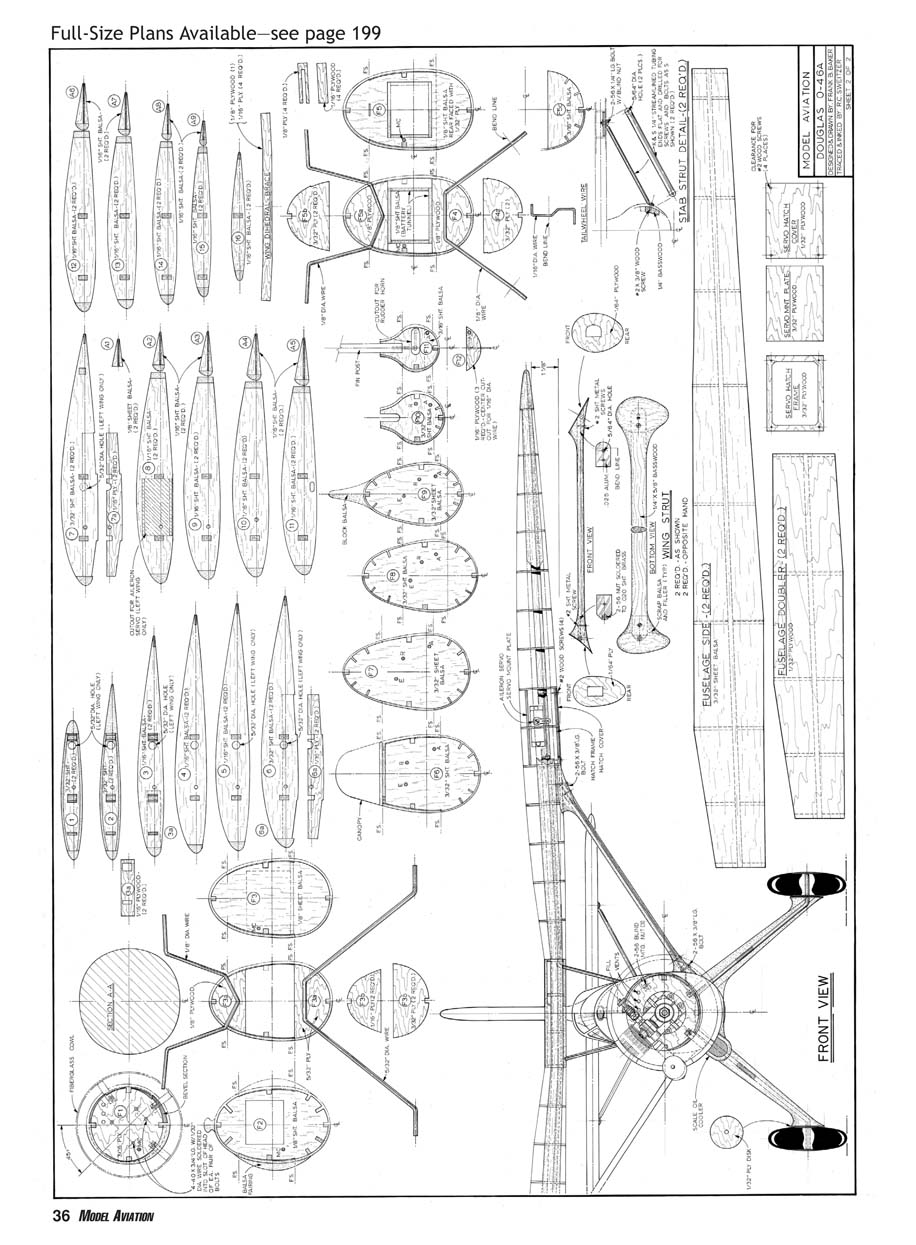
- I took the plans to the copy shop and had a copy made of the formers. I cut out the paper formers somewhat oversize and used spray adhesive to attach them to the proper materials. Former 5 is 1/8-inch balsa, faced on the rear side with 1/32-inch plywood.
- Before removing the paper from the cut formers, mark where the horizontal and vertical centerlines are located. Once the paper is removed, draw these centerlines on the formers. Place the plans on the work surface and pin the right-side 3/16-inch square stringer to them. Glue formers 2–7 to the stringer and add the left-side stringer. Use a triangle to ensure the centerlines are correct and the formers are perpendicular to the work surface.
- When the glue is dry, remove the assembly from the work surface. Attach the top stringers and add the four 3/16-inch square stringers that form the turtledeck. Add 1/16-inch plywood doublers to the inside of formers 3 and 4 and the motor-plate area. Use 1/32-inch plywood where the landing gear mounts.
- Glue the bottom sheeting in place using a 1/16-inch sheet with a 1/8-inch center gap and reinforce the wing saddle area with 1/32-inch plywood. Pin the fuselage on the plans and add the 1/16-inch top sheeting. When the glue is dry, remove the fuselage from the building board and sand it to shape. Add triangular stringers to fair the fuselage/turtledeck area.
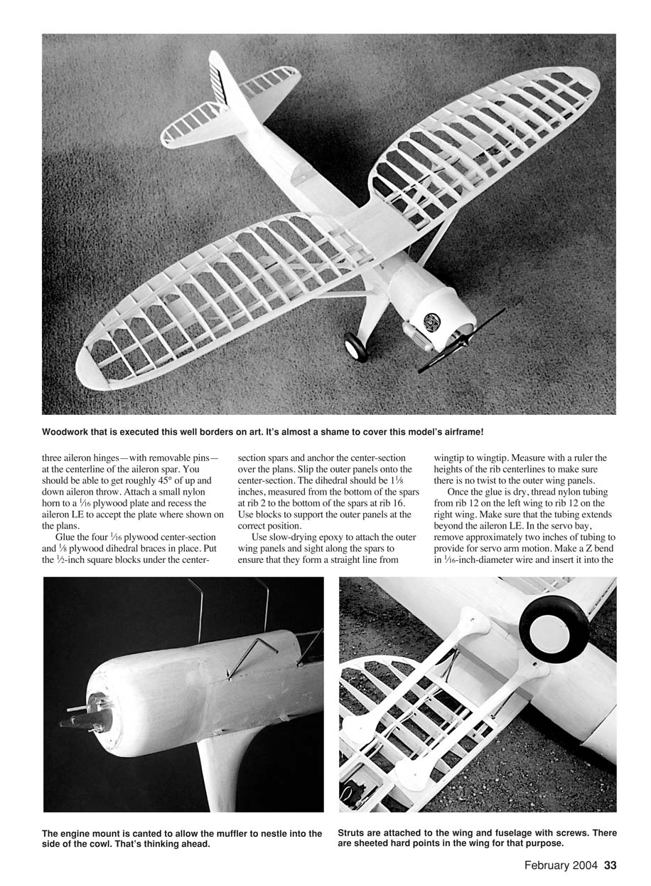
- Carve the nose block from soft balsa and glue it to the motor mount. Cement the motor mount to the firewall and add the cowl. Fit the cowling to the fuselage and carve to shape. Install the engine (O.S. .25) and set the needle valve to peak rpm for initial engine break-in.
- Use contact cement to glue the 3-inch-wide, 1/32-inch plywood doublers that go from F1 to F6 onto two 36-inch-long sheets of 3/32-inch balsa. Cut the fuselage sides from these with the 1/32-inch plywood facing the inside of the fuselage.
- Mark the location of the 1/16-inch-square stringers on the inside of each side. Glue just the stringer (with F2–F6 attached) to the right fuselage side and let the glue dry. Turn the fuselage over and repeat this process for the left fuselage side.
- Check that the stringers are aligned with the marks and that the tops of the sides meet correctly at the tail end. Glue the fuselage sides to F2–F7. When the glue is dry, add formers 8–11. Install the 3/16-inch square stringer at the top of these formers. Do not add the top or bottom 3/16-inch square stringers that go from F1 to F5 yet.
- Construct the firewall assembly: lay the fuel tank on K&S Engineering No. 254 tin plate and cut out the three pieces. Make the 90° bends in the body and solder the tab onto the side. Cut the slits in the end caps, bend the 3/16-inch strips 90° to the cap, and solder the front end cap onto the tank. Bend the short 7/16-inch pieces that stick up flush to the sides of the tank and solder them. Drill three 7/64-inch holes in the front cap per the plans.
- Looking at the front of the tank, the left hole is the fuel line and the other two are vents. Cut a length of soft-copper tubing that protrudes roughly 1/2 inch from the front of the tank, and bend the rest down to touch the bottom of the tank approximately 3/8 inch from the back of it. Insert the tube and solder it where it touches the bottom of the tank.
- Cut one vent tube so that it goes to the back of the tank where it is soldered to the top of the tank. Bend one tank vent tube at 90° and insert it so that its end is roughly 1/8 inch from the side of the tank near the front.
- All three tubes should protrude the same 1-1/2 inches from the front of the tank. Solder all three tubes to the front cap of the tank. Clean the inside of the tank, then solder on the rear cap. Be sure to test the tank for leaks.
- Cut the firewall from 3/16-inch plywood. From the top view the right and left sides are perpendicular to the front of the firewall; from the side view the top and bottom edges are at an angle. Use a sanding block to achieve the transition between these angles.
- Drill the mounting holes for a Dave Brown Products 2025 nylon engine mount. Insert four 3/16-inch-long, 4-40 bolts in the holes from the rear of the firewall. Align a pair of bolt slots and solder a length of thin music wire in the slots so the bolts cannot turn. Do this for the remaining pair of bolts. Cover both pairs of bolt heads and wires with electrical tape.
- Install three 2-56 blind nuts that will hold the cowl supports and back them up with routed-out pieces of basswood. Install the fuel tank by pushing the three copper tubes through the holes in the firewall and bend the tubes until the front of the tank is parallel to the firewall. Test-fit the firewall to the fuselage and modify the hole in F2 if needed to accept the tank. Make sure the tank does not cover the hole for the motor control nylon tube.
- Block up the fuselage and use a level to ensure the top of the fuselage is at 0° longitudinally and laterally. Epoxy the firewall assembly to the fuselage. Add triangle stock to support the junction of the firewall and the fuselage sides.
- I like to use Du-Bro nylon antenna tubes with braided cable for the rudder and elevator pushrods. Feed the nylon tubes through the holes in F10–F6 and let them extend two inches forward of F6. Solder 1/16-inch-diameter Z-bend wires to two lengths of cable. Insert the Z wires into the brass rudder and elevator horns.
- Feed the elevator cable into its nylon tube and position the stabilizer in its approximate position. A length of cable should protrude three inches from the front end of the tube; mark the cable for cutting at that point. Follow the same procedure for the rudder pushrod.
- Remove the tail feathers. Install the 1/16 x 1/4-inch top stringers from F7 to F9. Sheet the top of the fuselage from F7 to F9 with 1/16-inch balsa.
- Make the servo rails from 1/8-inch birch plywood and the servo-rail supports from 1/8-inch light plywood. Install small nylon clevises and brass connectors on the servo arms. Mount three HS-81 servos on the rails and position the assembly in the fuselage.
- Use your transmitter to cycle the servos, and mark the most rearward reach of the connectors. Cut off the nylon tubes 1/8 inch to the rear of that point. Use silicone sealant at several formers to hold the nylon tubing in place. Glue the servo-rail assembly into the fuselage.
- Slide a length of nylon tubing through the holes in F1–F3 and F5. Install a clevis and connector on the throttle servo arm and adjust the tube until adequate clearance is obtained and one inch of tubing protrudes from the firewall. Use silicone sealant at the back of F1 and the front of F5 to hold the tube in place.
- Since the rear of the fuselage is narrow, there is little support for the stabilizer. Use 1-inch-thick soft-balsa blocks to fill the area from F9 to F11 on each side of the fuselage. Leave a 3/8-inch slot between the blocks and rough-carve them to shape. Hollow the blocks but leave a thick area at the top to act as a base for the stabilizer. Glue the blocks in place and final-sand them. Carve the top of the blocks to the shape of the bottom of the stabilizer.
- Block up the fuselage so the top is at 0°. Lay a level across the cockpit area and make sure it is parallel to the work surface. Insert the elevator cable into its tube. With the elevator held in neutral, pin the stabilizer to the fuselage. Make sure it is parallel to the work surface. Cut the cable at the servo end and solder on the brass connector. Glue the stabilizer to the fuselage and recheck alignment before the glue dries.
- Attach the rudder to the vertical fin and insert the permanent hinge pins. Slip the rudder cable into its tube. Insert the fin post into the slot in F11. The bottom of the vertical fin should rest on the top of the stabilizer. Cut the pushrod cable to the proper length and solder the clevis connector to it. Glue the vertical fin in position. Use your transmitter to check the motion of the rudder and elevator and for proper throw. You may have to carve out a bit of F11 to get good clearance around the rudder horn.
- Use soft-balsa blocks to fill the junction of the vertical fin and stabilizer. These blocks should go one inch up the vertical fin and forward to halfway between F8 and F9. The sides of the vertical fin flow into the fuselage in a smooth, concave fashion—refer to a picture of the O-46 for reference.
- Install two 1/2-inch square basswood blocks that support the stabilizer struts. Drill a 1/16-inch pilot hole in each block after it is glued in place. Fabricate F12 using 1/16-inch-diameter music wire and a 1/16-inch birch plywood sandwich. Glue F12 to F11.
- Feed a length of Du-Bro antenna nylon tubing through the holes; the front end of the tube should be approximately 1/2 inch forward of the front servo rail. Leave three inches of tubing sticking out of F12. Use silicone sealer at F6 and F10 to secure the tubing.
Landing-gear and Front Assemblies
- Make the landing-gear and cabane-strut assemblies using the "sandwich" technique. Bend the forward landing-gear strut from 5/32-inch-diameter music wire and the rear strut from 1/8-inch-diameter music wire. Ensure the upper horizontal parts of both landing-gear struts are the same width.
- Cut four rectangular pieces of birch plywood (three 3/32-inch and one 1/16-inch) roughly 1/4 inch larger than F3b. Cut a slot in the 3/32-inch and 1/16-inch plywood pieces to fit the top of the 5/32-inch strut. Glue all four pieces together with epoxy and clamp them.
- When the glue has set, cut F3 from the plans and paste it onto the plywood sandwich so that its top is parallel to the line of the axles and the landing-gear legs exit the former where shown on the plans. Cut the sandwich to shape. Use the sandwich for the rear landing-gear strut and the cabane struts.
- To install the landing gear, block up the fuselage upside-down on the work surface with the cockpit area parallel to the surface. Use slow-drying glue and clamp F3b to F3. Adjust F3b until the axles are the same distance from the surface.
- Bend the rear landing-gear legs forward and put F4 in place. Mark where the legs touch the forward legs and bend the rear legs to match the angle of the front legs. Use masking tape to bind the legs, then make sure F4 goes up parallel to the work surface. Cut the axles and solder the wheels on. Glue the wheels and axle assemblies to the struts.
- Install the 3/16-inch square bottom stringer. The section from F1 to F2 will have to be cut from 3/16-inch sheet and spliced onto a 36-inch length of 3/16-inch square. Remove the masking tape, bind the landing-gear legs with copper wire, and solder them together. Now you can remove the fuselage from the bench.
- Cut the wing-strut tab rails from 1/8-inch birch plywood and make four 1/32-inch aluminum tabs per the plans. Position the rear tabs on the rail so the 5/64-inch-diameter hole is 3/16 inch beyond the outside of the fuselage. Use two 3/32-inch flush rivets to attach the tabs to the rear rail. Cut a 1/32-inch notch in the bottom of the fuselage sides and install the rear rail with the tabs facing the bottom of the fuselage.
- Attach the tabs on the front rail using #2 x 1/2-inch sheet-metal screws through the plywood into the tabs. Place the rail, tabs down, on the top of F3b and run the screws into the former.
- Build the battery tunnel from 1/8-inch balsa. The floor should be glued to F3, F4, F5, and both tab rails. Bend the 1/8-inch-music-wire wing cabane struts per the plans.
- Use the sandwich technique to fabricate F3a and F5a. Block up the fuselage so it is parallel to the work surface lengthwise and crosswise. Insert these two formers into the fuselage and use slow-drying epoxy. Use an incidence meter to ensure the wing will be at 1° incidence. Check that the wing center section will be parallel to the work surface.
- Install the fuselage top 3/16-inch square stringer. The section from F1 to F2 is cut from 3/16-inch sheet and spliced onto an 8-inch length of 3/16-inch square. Install 1/16 x 1/4-inch stringers on the bottom of the fuselage. Install two upper stub ribs and four lower stub ribs between F1 and F2; these ribs will be sanded to shape. Sheet the top and bottom of the fuselage from F1 to F5 with 3/32-inch balsa sheet.
- Cut thin poster board to the approximate size needed to cover half of the fuselage bottom from F5 to F12. When you achieve a reasonable fit, cut a right and left copy from 1/16-inch balsa sheet. Trial-fit the sheets to the bottom of the fuselage.
- To accommodate the compound curve, make a 1/4-inch-long V-shaped cut at F7 from the centerline downward along F7. Start with a narrow slot and increase it until the sheet conforms to all of the formers.
- After the bottom is sheeted, rough-carve a block of balsa for the tail cone. The upper part of the tail cone conforms to the bottom of the rudder. Hollow out the tail cone to a thickness of approximately 3/16 inch.
- Drill a 1/8-inch-diameter hole to accommodate the antenna tube, slide the block onto the tube, and glue the block to F11 and F12. Fill the rectangular space between F11 and the bottom of the stabilizer with 3/32-inch balsa. Final-sand the rear of the fuselage and the tail cone.
- On the left side of the fuselage just behind the rear cabane strut, drill a 5/32-inch hole diagonally down through F5a and F5 so that it exits F5 1/4 inch below the top of the fuselage side.
- Carve two 1-inch-thick, 3-inch-wide soft-balsa blocks to fit the side of the fuselage from F1 to a point 1 1/4 inches to the rear of F2. Rough-carve the blocks to match the shape shown in cross-section A-A on the plans. Add blocks at the top and bottom of the side blocks so the top and bottom of these side blocks curve around and join smoothly with the fuselage. Behind the A-A cross-section the blocks taper linearly to the side of the fuselage—this results from replacing the O-43's inline engine with a radial engine.
I have inspected the full-scale O-46A.
Landing Gear (Balsa Fairing and Final Fit)
- The landing-gear legs begin as inside and outside 3/8-inch balsa pieces. Rough-carve the fuselage ends of them to match the fuselage curvature. Press each half against the landing-gear wires, then carve a half circle in each along the depressions made by the wires. The halves should meet when placed over the wires.
- Final-fit the balsa to the fuselage curvature. Solder 3/8-inch-diameter, .010-inch brass plates to the main landing gear. Cut the balsa to fit the brass plate at the lower end of the leg and rough-carve the balsa to an airfoil shape.
- The junction of the top of the landing-gear leg and the fuselage forms a straight line parallel to the fuselage centerline. On the inner side the landing-gear leg flows into the bottom of the fuselage for its full length. At the wheel end the landing-gear leg curves out to the brass plate in all directions. You will need to add balsa to make both junctions.
- The inner panels that flow to the bottom of the fuselage are not attached to the fuselage and move downward when the landing gear spreads. The halves of the landing-gear legs can be glued to the wires and the fuselage, and then the final carving and sanding can be done. Use a cutoff wheel to trim the landing-gear axles to accept Williams Bros. 3/4-inch-diameter smooth-contour wheels.
Cockpit Hatch
- Glue 1/8-inch-square basswood strips to the inside of the fuselage along the top of both sides of the cockpit area. Cut a piece of 1/8-inch balsa sheet to fit the top of the fuselage from F5 to F7 for the cockpit floor.
- Lay plastic wrap over the cockpit area. From the outside, pin lengths of 1/8-inch-square basswood to the insides of the previous strips so the plastic wrap is between them. Add glue to the tops of the strips, and lay the 1/8-inch balsa cockpit floor on the glued strips. Place weights on top to hold down the balsa.
- When the glue is dry, remove the pins, the floor, and its strips. Add three 1/8 x 1/4-inch cross strips of basswood. At the rear add a 3/4-inch-wide piece of 1/8-inch plywood across the bottom between the two 1/8-inch-square pieces. On top add a 3/4-inch-wide piece of 1/16-inch plywood across the full width of the floor. Drill a 1/16-inch hole in the center of this piece that goes all the way through. Cut a piece of 1/8-inch plywood that fits across the fuselage under the 1/8-inch-square side strips and against F7, and glue it in place.
- Cut the hatch tab from 1/32-inch aluminum, drill several holes in it, and epoxy it to the front bottom of the hatch so the tab sticks out roughly 1/8 inch. Cut a slot in F5 to accept the tab.
- Rough-cut a balsa block to form the front of the cockpit under the windscreen, and glue it to the cockpit floor. Put the cockpit hatch down so the tab goes into the slot and the rear of the hatch slides down F7. You will have to sand the bottom of the rear of the hatch to half-round for it to slide into place. Final-shape and sand the front of the cockpit.
- With the hatch in place, drill a 3/64-inch hole in the bottommost 1/8-inch plywood and tap it for an 8-32 nylon bolt.
Wing Installation
- Because there is little space between the wing and the top of the fuselage, I covered the top of the fuselage from an inch in front of F2 to F5 with Sky Blue covering material. Cut four cabane-strut retainers from 1/8-inch plywood and four caps from 1/8-inch plywood. Slip the wing onto the four struts and put on the retainers and caps. Hold them in place with clamps.
- Block up the fuselage so the cockpit floor is parallel to the work surface lengthwise and sideways. Use your incidence meter to ensure the wing, measured at rib 7, is at 1° positive incidence.
- Attach a length of white thread to a pin and stick it in the top of the vertical fin. Use the thread to make sure the distance to the rear spar is the same at both wingtips. Measure the vertical distance from the work surface to the bottom of each wingtip and make sure they are the same. Adjust the wing on the cabane struts until all measurements are correct.
- Unclamp one of the struts. Coat both sides of the retainer and its slot with quick-setting epoxy. Replace the retainer, the cap, and the clamp. Repeat all measurements and check the incidence. Once the epoxy is set, repeat the process for each strut.
- Cut pieces of 3/32-inch sheet to fit the bottom of the center section. Make a cutout at the rear left corner for the servo lead to exit the wing. Feed the servo wire through the slanted hole in F5 and pull it until it will fit against the rear cabane strut. Solder the servo connector onto the wires.
- Glue the bottom sheeting on the center section. Glue the 3/32-inch sheeting on the top center section. These sheets provide a strong place to pick up the model.
- Cut a piece of 3/4-inch balsa to fit between the number-2 ribs and behind the rear spar. Cut the U-shaped rear contour with a band saw. Rough-carve the balsa to shape, glue it in place, and final-sand it. Add balsa along the outside of the bottom edges of the number-2 ribs to aid in covering.
Wing Struts
- The model's wing struts are functional and will be attached using 2-56 bolts. A distinguishing feature is the large fairings at each end of a strut.
- Cut 3/16 x 5/8-inch strips of basswood a bit longer than shown on the plans. Carve and sand them to an airfoil shape. Leave the fuselage end square and position it against the end of a strut tab. Mark the wing end at an angle to match the bottom of the wing as the center of the strut is positioned over the 2-56 blind nut. Cut the strut approximately 3/32 inch shorter than the mark.
- Use a saw to cut slits in line with the long axis of the strut airfoil, roughly 3/4 inch deep at both ends of the strut. Cut the upper strut tab from a piece of .020-inch sheet aluminum and bend the end to match the angle of the strut end. Fill the outer strut slot with epoxy and slip the tab in place; the bent end of the tab should fit tight against the slanted end of the strut.
- Cut the lower strut tab from .016-inch brass sheet, drill a 3/32-inch hole at the end, and solder a 2-56 nut to the tab. Insert the tab in the slit at the fuselage end until the nut barely touches the end of the strut.
- Recheck the strut's fit between the fuselage and the wing. When it fits reasonably well, use a short 2-56 bolt to attach the strut to a front fuselage tab. Repeat for the rear landing-gear strut and the cabane struts.
- Block up the fuselage so the top in the cockpit area is parallel to the work surface. Use your incidence meter to check the wing at rib 7 has 1° incidence. Mark the outer end of the strut where the 2-56 bolt will go through and screw into the blind nut. Remove the strut and drill a 3/64-inch hole perpendicular to the slanted end of the strut and through the aluminum tab.
- Drill 1/16-inch holes in each end of the struts that will go through the metal tabs. Run #2 x 3/8-inch sheet-metal screws through the struts and the tabs. Use a cutoff wheel to grind the pointed ends of the screws flush with the struts. This will ensure the tabs will not pull out. Reinstall the strut and put in both bolts. The incidence should not change. Repeat for the remaining struts. All four wing struts will remain bolted to the airplane.
- Cut eight 2-1/2 x 2-3/4-inch balsa blocks with the grain running the long dimension. Draw a centerline 1-1/16 inch from the front of the blocks. Position a block on the side of the fuselage and under a wing strut so the centerline is underneath the fuselage bolt head. Trace the wing strut onto the block; the lines will angle toward the rear. Copy these lines onto all blocks.
- Pair up the blocks and carve half an airfoil in each member of the pair between the slanted lines. Do not make these grooves too deep; they should just fit together.
- Slip a pair of blocks onto the strut and mark the fuselage curvature on the blocks with a soft pencil. Remove them and use a band saw to cut the curve. Slide the pair back onto the lower end of the strut, carve space in the ends to accept the strut tab and bolt, and glue the pair onto the wing strut. Make sure they are tight up against the fuselage.
- Repeat for the fairing at the upper end of the wing strut; note the upper end and the blocks are flush with the bottom of the wing.
- Locate the strut bolts, cut small holes to back out the bolts, and remove the strut from the wing. Cut the airfoil-shaped fairing ends from 1/64-inch plywood as shown on the plans. Cut a rectangular hole in a lower-end fairing piece so the strut and fairing can slip onto the fuselage strut tab. Epoxy the plywood to the strut's balsa and press the plywood hard against the balsa to get a tight fit. Repeat at the wing end of the strut.
- Make sure the airfoil shapes are pointed forward. Use a sharp knife to carve the fairings to shape, starting at the centerline of the nose and tail of the wing strut and ending at the centerline of the plywood end pieces.
- Carve and sand the top and bottom blocks to the shapes shown on the plans so the fairings flow smoothly onto the struts with no discernable joint. The ends of the fairings should be approximately 1/2 inch from the bolt holes. Repeat for the three remaining struts.
- When the struts are installed for good, be sure to put lock washers on the four 2-56 bolts at the fuselage sides to prevent loosening.
Cowling
- I fabricated the cowl from fiberglass cloth and epoxy resin using the "balloon" method; however, the cowl is simple and could easily be constructed from 1/32-inch plywood wrapped around balsa rings.
- I used a lathe to make a cowling form that was 3/4 inch longer than the cowl and had a 30° slant to have the cowl flaps open. Use a band saw to cut off this slanted part so you have two forms. When the resin has hardened, cut the two cowl pieces to length. Epoxy the slanted ring to the rear of the front part of the cowl and lay some fiberglass cloth on the inside of the joint to reinforce it.
- Cut holes in the cowl to fit the O.S. .25 FP or other engine of similar size, and support the cowl with 3/8-inch-wide aluminum angles bolted to the firewall at the three blind-nut positions. Eliminate pinholes with filler and sand the cowl.
- Now that the engine is mounted, finish fabricating the throttle pushrod. Use your transmitter to check the high and low positions.
Finish
- An excellent source for the O-46A's color scheme and markings is the Squadron/Signal booklet Air Force Colors Vol. 1, 1926–1942. It contains good color schemes and excellent pictures.
- The O-46A in the USAF Museum has a sky-blue fuselage with yellow wings and tail feathers. Most pictures of the aircraft show a metal fuselage with the rest of the airplane painted silver. I used a 1930s color scheme as depicted in the booklet.
- I sprayed three coats of LustreKote primer on the cowl, landing-gear legs, wing struts, and fuselage forward of the front cabane struts. Then I sanded those areas and sprayed on several coats of LustreKote Sky Blue.
- I covered the rest of the fuselage with Sky Blue EconoKote and covered the wings and tail feathers with Yellow EconoKote. When the ailerons and elevators were covered, I installed the permanent hinge pins. I cut the star insignia and the "US Army" on the bottom of the wing from trim film. I used a few other markings.
- I glued strips of 1/8 x 1/4-inch balsa behind each cabane strut and sanded them to an airfoil shape, then I covered the struts with the Sky Blue film. I painted the cockpit floor with gray butyrate dope.
- Although the O-46A has a long, enclosed cockpit, I opted for open front and rear cockpits. I molded the front windscreen and the central enclosure over balsa forms using .040-inch acetate sheet and heated it to 250°F in a kitchen oven.
- I used Williams Bros. 1/8-scale standard pilots for the pilot and the rear gunner.
- Fabricate the stabilizer struts from 1/4-inch streamlined aluminum tubing flattened at each end. Use #2 x 3/8-inch screws at the fuselage end and 2-56 x 1/4-inch bolts at the outer ends.
I think you will find the finished model appealing.
Flying
- After the first test flight I reflexed the ailerons up approximately 1/8 inch, which eliminated the aileron sensitivity. I added roughly 3/4 ounce of lead to the nose to reduce elevator sensitivity. The engine-mount bolts that point forward serve as mounting points for the weights.
- Takeoffs are accomplished by letting the model run on the ground until it achieves a high rate of speed. A touch of elevator will cause it to take off and initiate a shallow climb. Because of the model's high parasol wing and narrow landing gear, it does not like crosswind takeoffs. Most important, do not try to "horse" it off the ground before it attains adequate speed.
- The O-46A is fast in the air; you can back off on the throttle once it reaches a reasonable altitude. When this model passes overhead, the sight of the yellow elliptical wings against the blue sky brings back the days of the 1930s Air Corps.
- Landings are beautiful. Throttle back to idle on final approach and let the model glide in. It will have a flat but slightly nose-down glide, and once a few feet above the ground, a light touch of elevator will result in a perfect three-point landing.
MA
Frank B. Baker 5301 Burnett Dr. Madison, WI 53705
Transcribed from original scans by AI. Minor OCR errors may remain.

