
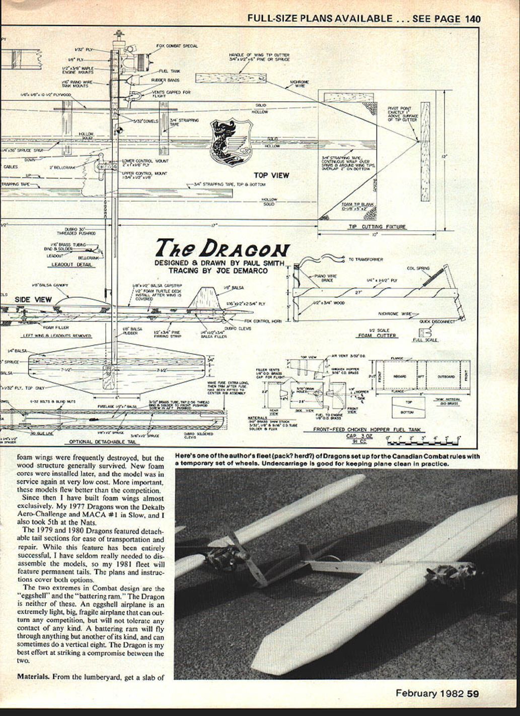
Dragon
SLOW COMBAT is a most popular control-line event in many parts of the country. Despite its strong following, there has been an almost complete absence of kits or published plans. This is probably a result of the continuous series of rules changes that have eliminated most of the competitive designs every two years.
In 1977, inboard tanks and very short noses prevailed. The 1978–79 rules stretched noses to 5 in., while deregulating tank location and deleting landing gear. The 1980–81 book outlawed all forms of inboard tanks. Fortunately, there were no changes for 1982–83 that would disallow any equipment.
Considering the rules instability, it's easy to see why no one has had time to produce a kit or a magazine article. One positive effect of this has been an interesting variety of equipment at every contest.
Fuel tanks
The main factor that sets Slow Combat apart from other events is the requirement for a suction fuel system. In Fast, FAI, and 1/2 A Combat, the contestant simply opens up the venturi as wide as possible and hooks up a pressure tank. The fuel tank and venturi size are the key factors that make one contestant more competitive than another. Slow Combat models are faster and tighter-turning than other models which run on suction. Sport and Stunt setups do not work in this event.
Prior to 1978, I went through a series of conventional, uniflow, and clunk tanks that were not really satisfactory, but were equal to the competition. The June 1978 issue of Model Aviation contained an article by Don Jehlik on "chicken hopper" tanks that completely changed my life, at least with respect to Slow Combat. I built a chicken hopper and soldered it onto a Perfect square tank. The first test flight was a perfectly smooth and steady run from start to finish. I haven't used any other form of suction tank since. The principle is that the engine draws fuel only from the tiny "hopper" and thus is unaffected by sloshing, G-forces, and decreasing volume in the main tank. Longer, faster, and smoother runs are the result; no more rich-at-the-start/lean-at-the-end runs, no more sagging as you enter a tight maneuver.
The chicken-hopper tank is vital to the success of the Dragon. It is too fast and tight-turning to work with a conventional tank.
Airframe design
Combat contests are won by beating a series of four to six opponents. Quality airplanes are needed to win each match, while a quantity of models is needed to win the contest. At the 1976 World Championships, I saw the British solution to this challenge, the foam Superstar. These models featured balsa and hardwood center sections and foam wings. In crashes, the foam wings were frequently destroyed, but the wood structure generally survived. New foam cores were installed later, and the model was in service again at very low cost. More important, these models flew better than the competition.
Since then I have built foam wings almost exclusively. My 1977 Dragons won the Dekalb Aero-Challenge and MACA #1 in Slow, and I also took 5th at the Nats.
The 1979 and 1980 Dragons featured detachable tail sections for ease of transportation and repair. While this feature has been entirely successful, I have seldom really needed to disassemble the models, so my 1981 fleet featured permanent tails. The plans and instructions cover both options.
The two extremes in Combat design are the "eggshell" and the "battering ram." The Dragon is neither of these. An eggshell airplane is an extremely light, big, fragile airplane that can outturn any competition, but will not tolerate any contact of any kind. A battering ram will fly through anything but another of its kind, and can sometimes do a vertical eight. The Dragon is my best effort at striking a compromise between the two.
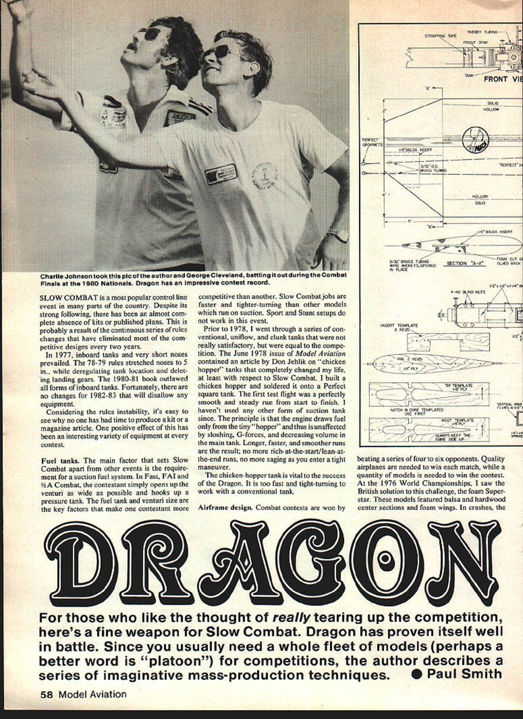
For those who like the thought of really tearing up the competition, here's a fine weapon for Slow Combat. Dragon has proven itself well in battle. Since you usually need a whole fleet of models (perhaps a better word is "platoon") for competitions, the author describes a series of imaginative mass-production techniques.
Materials
From the lumberyard, get a slab of insulating foam, 2 x 8 ft., 2 in. thick. Density is normally 1 lb. per cubic foot. Genuine Dow Styrofoam, the light blue stuff, is about twice that density. It makes the planes last (and fly) like furniture. Pick up an 8-ft. length of 1/8 x 3/4 in. furring strip. If you don't have some scrap wood around the house, you will also need a 6 x 1 ft. piece of plywood or particle board for the foam-cutting fixtures.
For either fuselage type, you'll need:
- 1/2 x 3/4 in. hardwood motor mounts
- 1/8 in. and 1/32 in. plywood
- 1/8 in. and 5/32 in. dowels
- 1/4 x 3 in. and 1/8 x 3 in. balsa
- 36-in. spruce in 1/4 x 1/4 (2 required) and 1/8 x 1/4
- Perfect leadout wires
- Fox 2-in. bellcrank and control horn
- 1/16 in., 3/32 in., and 1/8 in. brass tubing
- Dubro 30-in. threaded pushrod and clevis
- 4-40 x 1-1/4 in. bolts and blind nuts
The detachable tail also requires:
- 1 x 1/2 x 36 in. balsa
- 1/8 x 1/2 in. and 3/16 x 1/2 in. spruce
- 6-32 x 2 in. bolts, blind nuts, and a solder-type clevis
Adhesives and coverings:
- Titebond for most joints
- Hot Stuff (CA) only on wood-to-wood
- Hobbypoxy Formula 2 for fuel-proofing the motor mount and for high-stress areas
- Low-temperature covering such as Solarfilm or GBC laminating film for foam wings
- High-temperature covering such as MonoKote or Fascal for fuselage, tail, and canopy
- Nylon-reinforced strapping tape (e.g., 3M) to prevent wing flex
Foam-cutting equipment
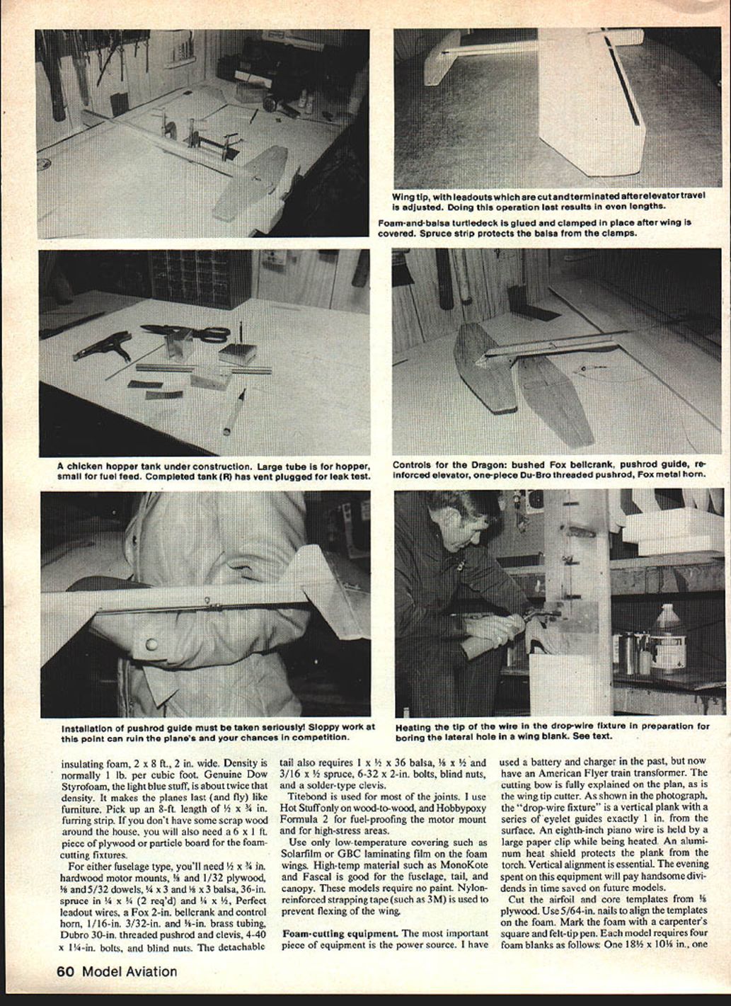
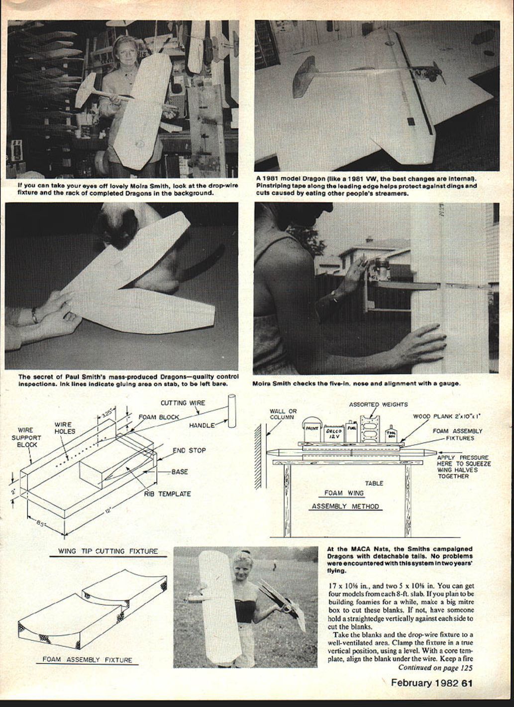
The most important piece of equipment is the power source. I have used a battery and charger in the past, but now have an American Flyer train transformer. The cutting bow is fully explained on the plan, as is the wing tip cutter. As shown in the photograph, the "drop-wire fixture" is a vertical plank with a series of eyelet guides exactly 1 in. from the surface. An 1/8-in. piano wire is held by a large paper clip while being heated. An aluminum heat shield protects the plank from the torch. Vertical alignment is essential. The evening spent on this equipment will pay handsome dividends in time saved on future models.
Cut the airfoil and core templates from 1/8 in. plywood. Use 5/64-in. nails to align the templates on the foam. Mark the foam with a carpenter's square and felt-tip pen. Each model requires four foam blanks as follows: one 18 3/8 x 10 1/2 in., one 17 3/8 x 10 1/2 in., one 16 3/8 x 10 1/2 in., and one 15 3/8 x 10 1/2 in. You can get four models from each 8-ft. slab. If you plan to be building foamies for a while, make a big mitre box to cut these blanks. If not, have someone hold a straightedge vertically against each side to cut the blanks.
Take the blanks and the drop-wire fixture to a well-ventilated area. Clamp the fixture in a true vertical position, using a level. With a core template, align the blank under the wire. Keep a fire extinguisher or water bucket handy. Heat the point of the wire red hot. Set the torch down, and release the paper clip. The wire should pierce a straight hole through the blank. You can make the hole larger or smaller by varying the temperature of the wire. Excessive heat can cause an oversize hole, while too little heat can result in the wire wandering off center. You may as well pierce all four sets while you're at it. Do not pierce the 5-in. tip blanks.
Next comes the hot-wire cutting. Clear off a large enough area for the cores to lay flat on the bench. With the blank and templates held square on the bench and the templates square with the leading edge, nail the templates to the foam. Always keep the same setup so as to avoid creating a warp if the templates aren't quite symmetrical. Adjust the transformer to give a good, clean cut without dragging the wire or making too wide a cut. Practice on some scrap. After cutting the spar notches, disconnect the wire, and thread it through the pierced hole. Cut the void, then disconnect the wire again, and pull out the wire and the scrap. Use the same nail holes to align the airfoil templates. Airfoils are cut in four separate passes, always starting from the spar notch. I now have a fixture for the front spar slot; on my earlier models, the front spar slot was cut with manually held straightedges.
Tips are cut with one airfoil template and the tip-cutting fixture. Cut the top first, then the bottom, without removing the top scrap. Be sure to position both the template center line and the pivot point exactly 1 in. above the base.
Glue the outboard wing tips to the outboard wings at this time. Position the insert wing tip templates on the inboard tip, and cut out the insert. Glue the leadout mount into the tip, and glue the tip to an inboard wing. Sand or cut 1/8 in. off the top of the scrap, and save it to install later. Use Titebond for these glue joints.
Make two 24-in. assembly fixtures at this time. Use the airfoil templates to cut the two cradles from foam, then make clearance notches for the engine mount and tail as required.
For a one-piece fuselage, cut a furring strip to length, and glue on pine or spruce spacers to bring the front end up to a dimension of 1.25 in. When dry, file in the spar notches.
For a two-piece fuselage, file bellcrank-mount notches in a piece of 1/8 x 1 in. balsa, then glue 3/16-in. spruce to both top and bottom. When dry, cut the center rib from the tail boom. Sand the center rib to match the airfoil, then sand the tail boom to fit the rib. Using the center rib for alignment, glue the 3/16-in. capstrips to the tail boom. When dry, sand off excess glue, and drill for the two assembly bolts (6-32 x 2 in.). Glue in the upper and lower bellcrank mounts and peg with 1/8-in. dowel. Remember, this peg only goes through the center rib, not the tail boom. Round off the aft end of the tail boom, and cut the stab slot.
Motor mount
Glue and clamp the hardwood beams to the center rib or fuselage. While this is drying, add the two vertical spacers. When dry, glue and clamp the 1/32-in. outboard and 1/8-in. inboard plywood doublers. The outboard doubler must be high-strength plywood such as Sig's. The inboard doubler can be the lighter 3-ply type, such as supplied by Balsa USA. Sand the motor mounts and doublers to shape, and drill motor bolt holes (9/64 in.), tank wire hole (1/16 in.), and dowel holes (5/32 in.). Install and sand the dowels smooth. Using a Dremel tool with an end-mill cutter, fit the engine mount to the engine.
Mix up a small batch of Hobbypoxy Formula 2, warming it with a heat gun, and stirring with a stick until it thins out to the consistency of clear dope. Spread the warm glue over the motor mount, being sure to get it into the bolt holes. Apply more heat and finger-paint it smooth. A final application of heat will remove the fingerprints. Hang the assembly nose-down to dry.
Control system
This system is designed with reuse in mind. The Fox 2-in. bellcrank provides adequate stability and better strength with less weight than the more popular 3-in. model. Cut two 3/8-in. sections of 3/32-in. tubing for leadout guides, and slip onto a full-length pack of Perfect BC leadout cable. Cut two 1-in. sections of 1/16-in. brass tubing for bushings, slip onto the ends, bend to a horseshoe shape, insert in the bellcrank, bind with copper wire, and solder. The leadouts are cut and terminated after the final assembly of the airplane.
The one-piece model uses a Du-Bro 30-in. threaded pushrod with a Z-bend at the bellcrank end. The two-piece version uses the same rod cut behind the trailing edge. The short length of 3/32-in. brass tube is tapped with a 2-56 thread and bound and soldered to the front end and terminated at the control horn with a soldered clevis. A Fox metal control horn is used.
A heavy-duty pushrod guide is fabricated from 1/8-in. tubing bound and soldered to piano wire and screwed and epoxied to the fuselage. The failure of a guide could cause a loss of control when you need it most.
Tail and canopy
The canopy and rudder are made from 1/8 in. balsa and covered before installation. The stabilizer is 1/8 in. balsa with a 1/4 x 1/2 in. spruce spar at the trailing edge. The elevator is 3/32 in. balsa with a 1/32 in. plywood patch in the center to mount the control horn and prevent splitting along the grain. Mark the gluing area with felt-tip pen, then cover and hinge the stab and elevator before assembly. I use either Fascal or Monokote for both covering and hinge tape. The "iron-on hinge" method described in the April 1979 Model Aviation has been used with complete success on all my models since the article was published.
Assembly
Glue the front vertical spar into the outboard wing, taping with masking tape. Sand any runs from the motor mount, redrill (1/8 in.) the mounting bolt holes, and recheck the engine fit. Glue the outboard wing to the fuselage center rib, if you're building the two-piece model. Use two chains of rubber bands to hold the assembly together while drying. Some scrap cardboard under the bands is needed to protect the foam wing tip.
While this is drying, install the stabilizer and set up the controls.
When the rubber bands can be removed, fit the inboard wing onto the model. This may require several tries to get the proper clearances cut for the controls and motor mount.
The assembly fixture is simply two 24-in. foam slabs with airfoil shapes cut into them, a wood plank, some waxed paper, and whatever assorted weights are handy. Glue the inboard wing and spars to the airplane with Titebond, place the model between the waxed-paper-covered foam cradles, and stack the plank and weights on top. One wing tip should be against a wall so you can press against the other to get a good tight joint.
The next day, remove the model from the fixture, and install the leadouts. They are pinned to the balsa inserts with wire wickers, then glued with epoxy or Hot Stuff with baking soda. The scrap foam is then re-inserted. The one-piece model also needs foam fillers between the wings over the fuselage. The two-piece model needs balsa fillers behind the spars.
When these are all dry, give the whole wing a light sanding to blend the parts together and remove any glue runs. Clean the wing with a soft brush on a vacuum cleaner. Apply nylon strapping tape as shown on the plans. This is essential to prevent flexing and breaking of glue joints. You may also want to add a strip of tape near the leading edge to prevent streamers from coming too far into the foam. Add AMA numbers and any other decorations before covering.
Covering
Very low-heat material is needed to avoid melting the foam. Cut four pieces, 25 x 12 in., to allow overlapping at tips, center, and leading and trailing edges. Lay a piece of covering over one-quarter of the wing, and iron a line down the spar. Work the iron away from this line toward the leading and trailing edges. This will keep air bubbles from being trapped under the covering. Cut slits in the covering where it laps around the tip and edges; this also helps to prevent wrinkling. Do the remaining three sides in the same way.
The fuselage of the one-piece models needs to be built up with a foam turtledeck, capped with a 1/8 in. balsa strip. The front of the strip needs to be tacked in place with Hot Stuff while the remainder is clamped in place under a spruce strip and glued with Titebond.
Fuel-proof the joint between covering and motor mount with warmed Hobbypoxy. Cover the fuselage with plastic film. Install the pushrod guide, rudder, canopy, and fuel tank wires.
Fuel tank construction
Materials:
- 0.010-in. brass shim stock
- 3/32 in., 1/8 in., and 9/16 in. O.D. brass tubing
- Sears 60/40 solder and Kester soldering paste (flux)
- Weller electric soldering gun (preferred)
- Wood form in the shape of the tank (helpful)
Cut out the three parts of the main tank, solder the front seam, then add the top and bottom. Sharp edges should be filed smooth, taking care to clean up the lead solder.
Insert the two filler tubes and pressure-test under water. When the tank is airtight, drill the four holes in the outboard side and the two in front. Install the fuel feed and vent tubes. Make the chicken hopper out of a short piece of 9/16-in. tubing with a shim-stock lid. File the inside of the hopper for a tight fit to the tank, and solder in place. Note that the hopper is inset above the centerline to compensate for hinging out inverted. Pressure-test the tank under water again.
Clean the tank with hot water and baking soda, and install on the Dragon with a foam rubber pad underneath and rubber tubing over the tank wires for protection. The fuel filter may need frequent cleaning at first on a new tank.
Engines
The Fox Combat Special Mark III has been the standard engine for the Dragon. Future models will feature the Mark IV, which I have not yet had the opportunity to test. Super Tigre G21s have been used with some loss of speed, and an OS .36 has been used with some success in local contests. The OS equals the Fox in speed, but adds too much weight for good maneuverability, in my opinion.
The Fox consistently pulls the Dragon at 92 to 94 mph on 15% nitro. One exceptional engine was able to break 100 several times on 30%. When they get under 90, something is wearing out.
My only modifications are to replace the rear bearing with a Hoover-NSK RB 78 and to use a Super Tigre needle valve assembly. The venturi insert is wrapped in polyethylene plastic to form an air seal. The head clearance is set at .015 to .018 in. This is essential to good performance. Break-in is via bench running with a 9-6 prop cut to 8 in. Lapping is only required on certain very tight replacement pistons and sleeves. I like the Fox because it runs right out of the box and doesn't take my time away from more important things (like fuel tanks).
Flying
The completed airplane should weigh 26.5 ounces and balance at 25% of the chord, slightly outboard of the thrust line. The side-mounted engine, leadout position, and offset wing provide all the line tension necessary. I do not recommend tip weight, engine out-thrust, or rudder offset.
Make the initial test flight with the engine set on the rich side until you become familiar with needling an engine on the chicken hopper tank. Foams can become warped in covering or assembly, so check it out, and use the iron or trim tabs to correct a warp. If the plane feels too sluggish, go to a more aft CG or more control. I've never had one come out tail-heavy yet. Top Flite 9-5s or 9-6s cut to 8-6 work well.
When you have four Dragons tested and trimmed out, you should be ready for any contest.
Transcribed from original scans by AI. Minor OCR errors may remain.

