
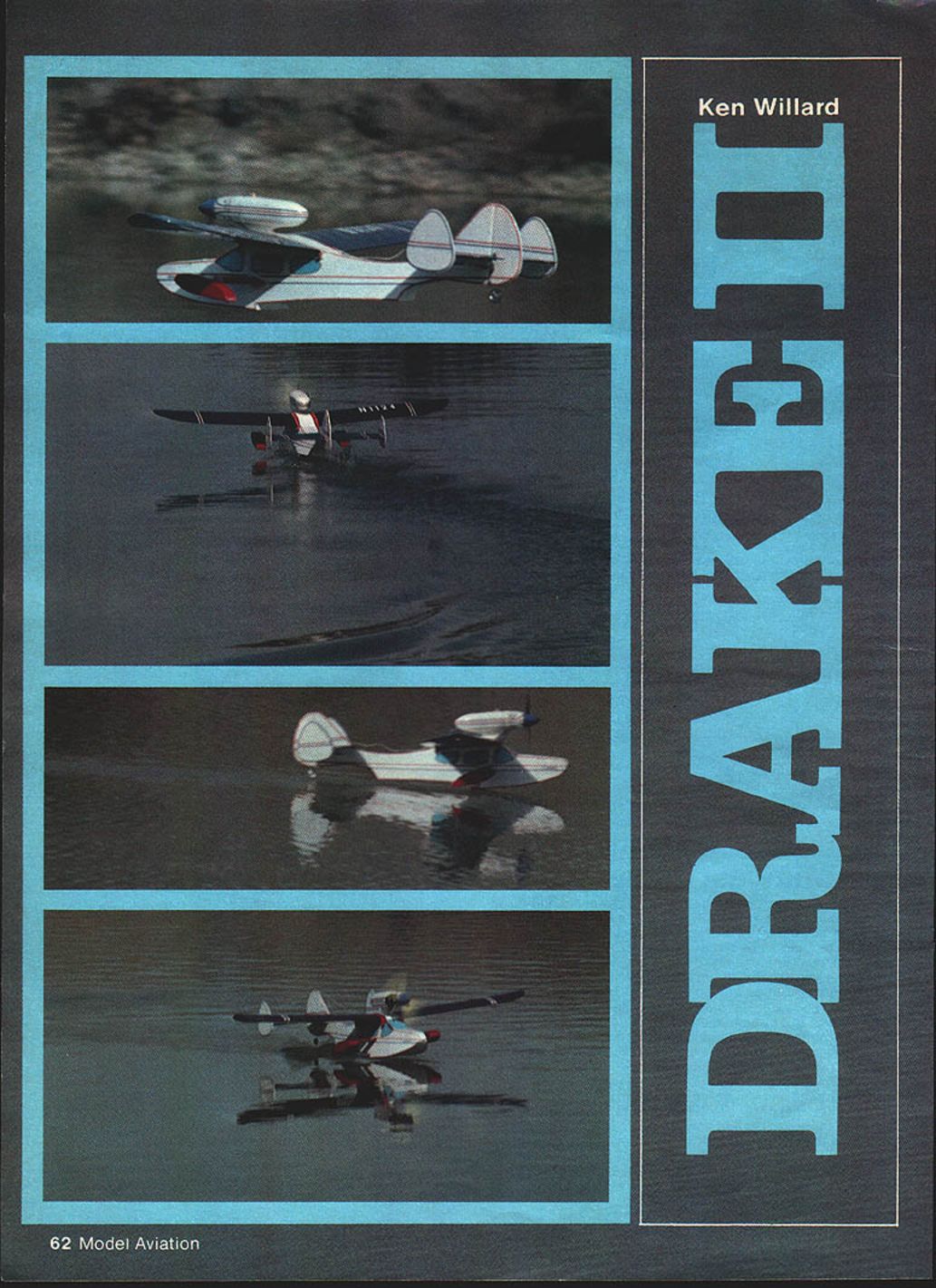
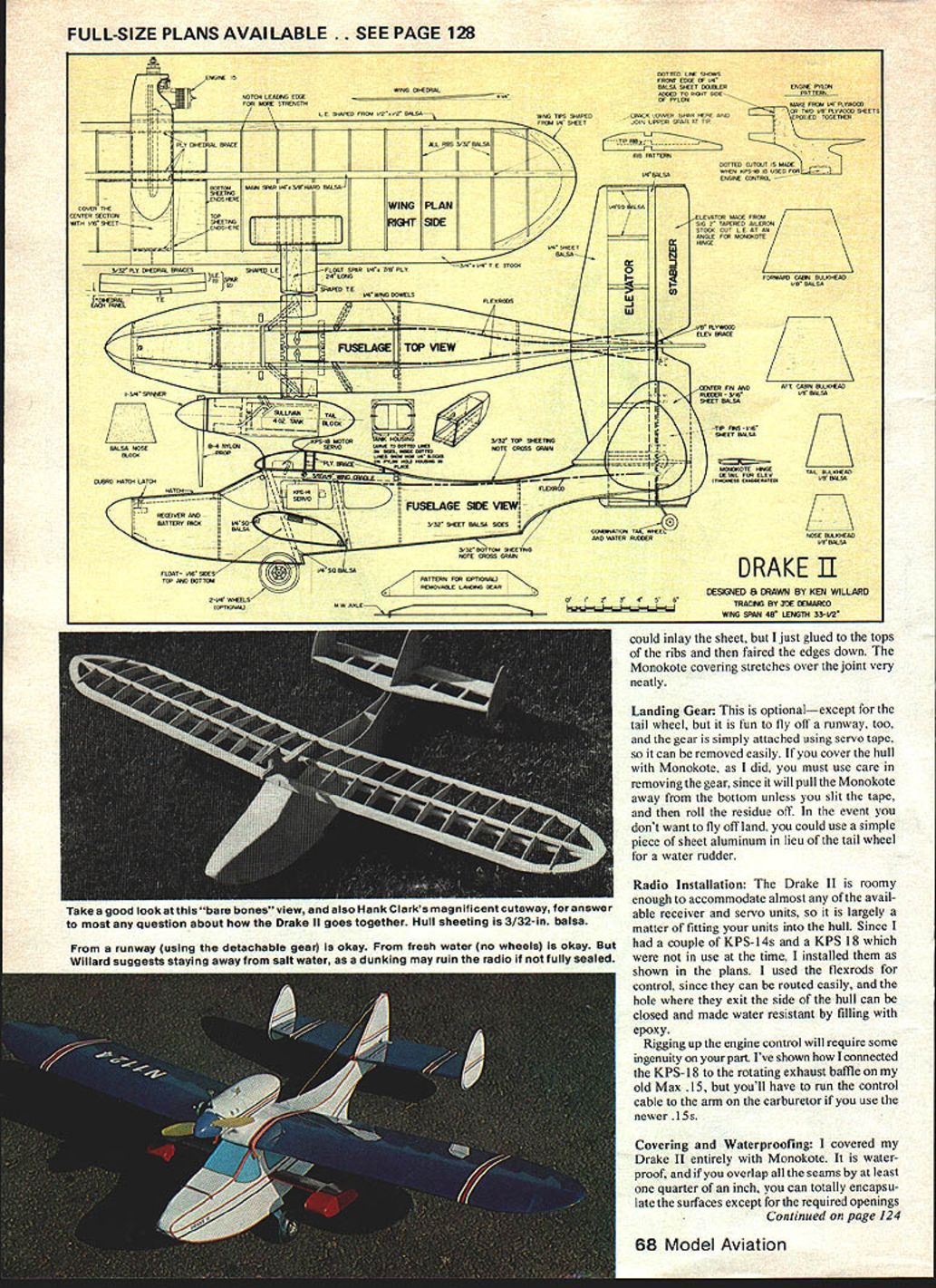
Drake II
Ken Willard
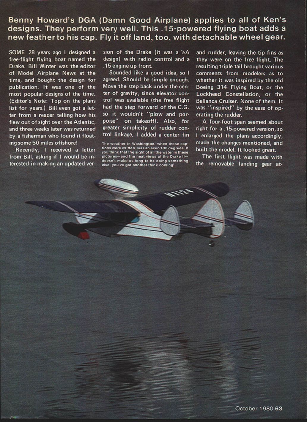
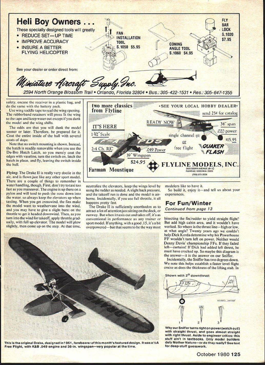
Some 28 years ago I designed a free-flight flying boat named the Drake. Bill Winter, then editor of Model Airplane News, bought the design for publication and it became one of the most popular designs of the time. Recently Bill asked if I would update the Drake (originally a 1/2A free-flight design) as a radio-controlled version with a .15 engine up front. I agreed.
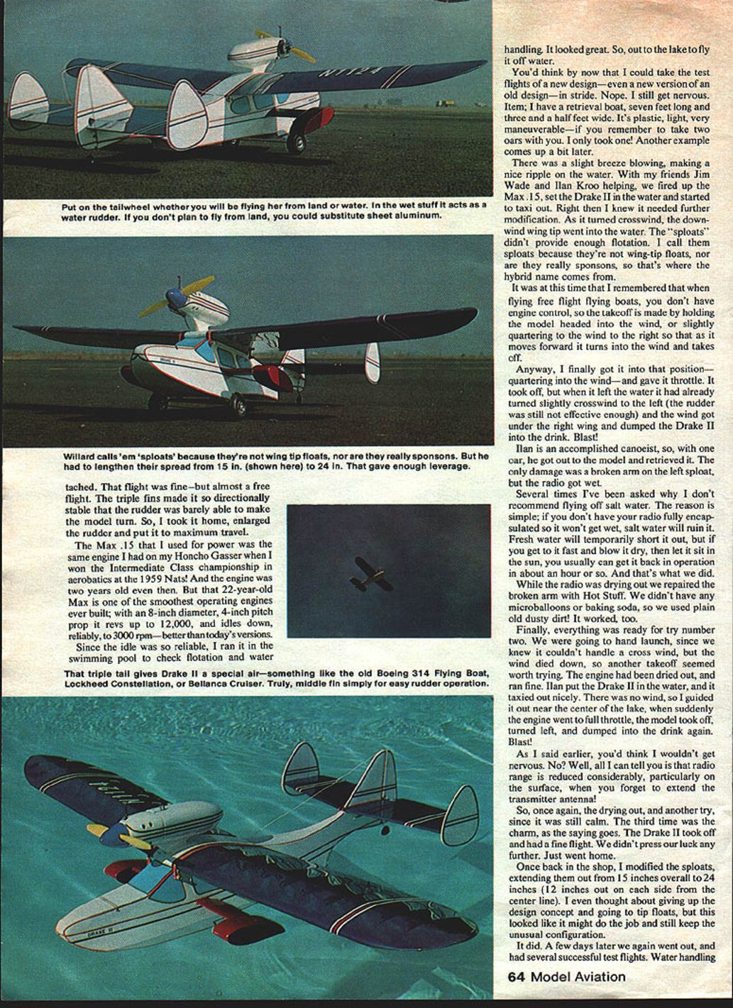
To convert it I moved the step back under the center of gravity (the free flight had the step forward of the C.G. to avoid "plowing and porpoising" on takeoff). For simpler rudder-control linkage I added a center fin and rudder while leaving the tip fins. The resulting triple tail was purely to make rudder operation easier — though many modelers compared its look to the Boeing 314, Lockheed Constellation, or Bellanca Cruiser.
A four-foot span seemed about right for a .15-powered version, so I enlarged the plans and built the model.
First flights and modifications
The first flight, made with removable landing gear attached, was fine but almost free-flight trim. The triple fins made the Drake II directionally stable; the rudder was barely able to make the model turn. I took it home, enlarged the rudder and set maximum travel.
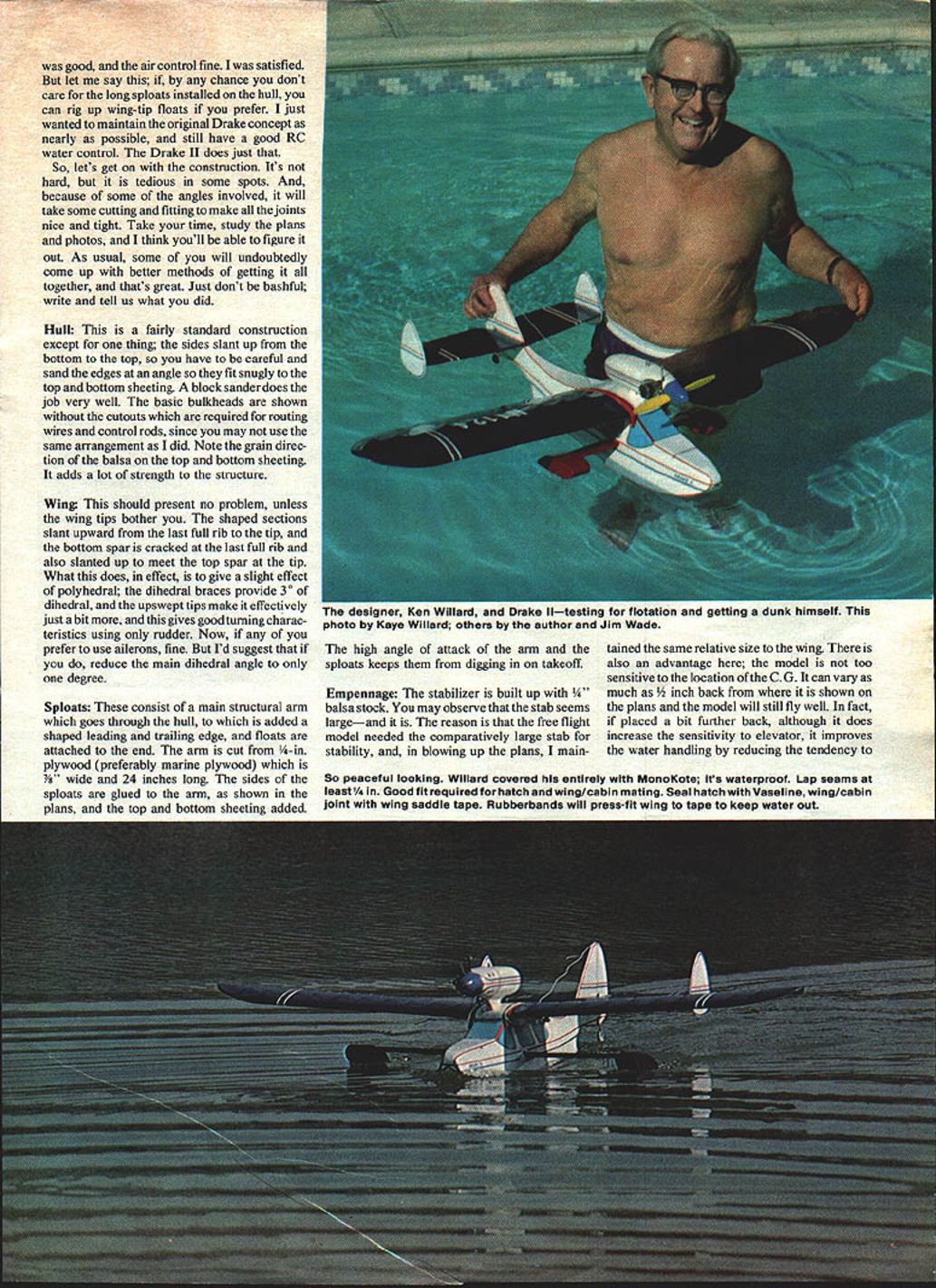
Power was a Max .15 — the same engine I used on my Honcho gasser when I won the Intermediate Class championship in aerobatics at the 1959 Nats. I ran an 8" diameter by 4" pitch prop that revved to about 12,000 rpm and idled reliably to about 3,000 rpm. Because the idle was so dependable I ran a swimming-pool check for flotation and water handling.
Out at the lake I used a small retrieval boat (7 ft long, 3½ ft wide). A slight breeze produced a ripple on the water. With friends Jim Wade and Ilan Kroo helping, I fired up the Max .15, set the Drake II on the water and started taxiing. As it turned downwind, a wing tip went into the water — the sploats (my name for the wing-tip floats / not quite sponsons) didn’t provide enough flotation. On takeoff the model had already turned slightly crosswind and the wind got under the right wing; the Drake II dumped into the water. Ilan, an accomplished canoeist, retrieved it with an oar. Damage: a broken arm on the left sploat and a wet radio.
I don’t recommend flying off salt water unless your radio is fully encapsulated — salt will ruin electronics. Fresh water will usually only temporarily short things out if you recover and dry them quickly. We blew the radio dry, left it in the sun, and it came back to life in about an hour. The broken arm was repaired with Hot Stuff epoxy and filler; we didn’t have microballoons or baking soda, so plain dusty dirt worked as a filler.
Ready for try number two, we planned a hand launch because the crosswind was still a concern. The wind died; the engine ran fine; the model taxied out nicely. Suddenly the engine surged to full throttle, the model turned left and dumped again. Once more the radio got wet and had to be dried.
On the third try the Drake II took off and flew well. Back in the shop I modified the sploats, extending them so they were 24 inches overall (12 inches outside the centerline). I considered switching to conventional tip floats but kept the sploat concept to retain the Drake’s unusual configuration. A few days later we had several successful test flights and water handling was satisfactory.
Construction
It's not hard, but some parts are tedious and require careful cutting and fitting because of angled joints. Study the plans and photos and take your time. Below are the principal construction items and tips.
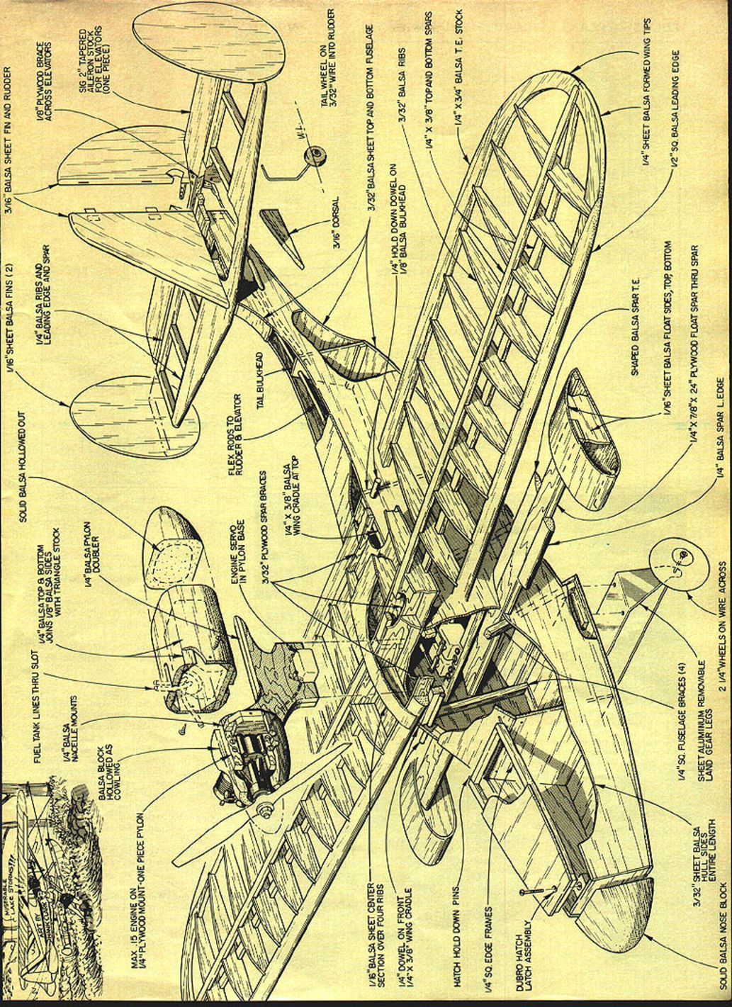
Hull
- Fairly standard construction except that the sides slant up from bottom to top, so sand edges at an angle for snug joints. A block sander works well.
- Basic bulkheads on the plans are shown without the cutouts required for routing wires and control rods — add those as needed for your installation.
- Note the grain direction of the balsa on the top and bottom sheeting; correct grain adds strength.
- Coat the inside of the hull with several coats of dope to help waterproof and protect against eventual dunking.
- For hatch sealing: coat the hatch edges with Vaseline, use a Du-Bro Hatch Latch and leave the switch inside the hull when flying. Use wing saddle tape to seal the wing opening; rubber bands will press-fit the wing to the tape and help keep water out.
Wing
- The wing is straightforward unless the tips bother you. The shaped tip sections slant upward from the last full rib, and the bottom spar is stepped at the last full rib to meet the top spar at the tip.
- This gives a slight effective polyhedral: the dihedral braces provide 3° and the upswept tips add a bit more, producing good turning characteristics using rudder only.
- If you prefer ailerons, reduce the main dihedral to about 1°.
Sploats (wing-tip floats)
- Consist of a main structural arm that goes through the hull, with shaped leading and trailing edges and a float attached to the end.
- Cut the arm from 1/4-in. plywood, about 3/8 in. wide and 24 in. long.
- Glue the sploat sides to the arm, add top and bottom sheeting. The high angle of attack of the arm and sploats keeps them from digging in on takeoff.
- I eventually extended the sploats to 24 in. overall (12 in. each side of the centerline) to provide sufficient leverage and flotation.
Empennage
- Stabilizer built up from 1/4" balsa stock. The stab is relatively large — retained from the free-flight Drake to provide stability after scaling up. The large stab also makes the model tolerant of some C.G. variation (up to about 3/8" aft of the plans location).
- Center fin and rudder cut from 3/16" balsa. Tip fins cut from 1/16" balsa sheet.
- Elevators made from 2" aileron stock; cut the forward edge at an angle to accommodate Monokote hinges when down elevator is applied.
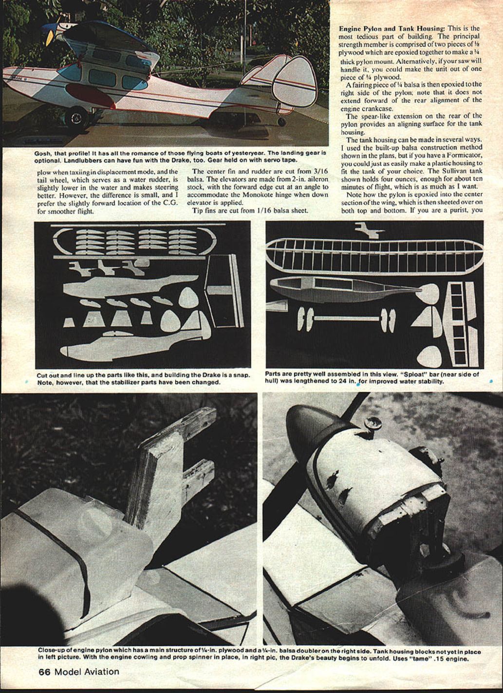
Engine pylon and tank housing
- One of the more tedious parts. The principal strength member is two pieces of 1/4" plywood epoxied together to form the pylon mount (or make it from one thicker piece if your saw will handle it).
- Epoxy a fairing piece of 1/4" balsa to the right side of the pylon; it should not extend forward of the rear alignment of the crankcase.
- A spear-like extension on the rear of the pylon aligns the tank housing.
- The tank housing can be built from built-up balsa as in the plans or molded from plastic if you have the tools. The Sullivan 4-oz tank gives about ten minutes of flight, which is adequate.
Landing gear
- Optional except for the tail wheel; flying off a runway is possible. The gear is attached with servo tape so it can be removed easily.
- If you cover the hull with Monokote, be careful removing the servo tape — slit the tape first and roll off the residue to avoid pulling the covering away.
- If you don’t fly off land you can substitute a simple piece of sheet aluminum in lieu of the tail wheel as a water rudder.
Radio installation
- The Drake II is roomy enough for most receivers and servos. Fit your units into the hull and add cutouts in bulkheads for routing as required.
- I used KPS-14 and KPS-18 units and flexrods for control; flexrods route easily and the exit hole can be sealed with epoxy to be water resistant.
- If using older engines with a rotating exhaust baffle, you can connect a KPS-18 for engine control as shown in the plans. For newer .15 engines you’ll need to route a control cable to the carburetor’s throttle arm.
- For water safety: encase the receiver in a plastic bag and do the same for the battery pack.
Covering and waterproofing
- I covered the Drake II entirely with Monokote. Overlap seams at least 1/4" to fully encapsulate surfaces except for required openings.
- The Monokote covers joints neatly; you can glue top sheeting to rib tops and fair the edges down before covering.
- Use wing saddle tape at the wing/cabin joint to help keep water out. Rubber bands will press-fit the wing to the tape.
- Expect to dunk the model sooner or later — prepare for that by coating the hull interior and protecting electronics.
Flying
The Drake II is docile in the air and flies like a conventional sport model. A few notes on water handling:
- Don’t taxi too fast when maneuvering. The pylon-mounted engine tends to push the nose down, so keep elevators up while taxiing.
- In a crosswind the fins make the model want to weather-vane into the wind; a slight burst of throttle can help get it headed downwind.
- To take off: turn into the wind, apply throttle gradually with full up elevator. The model will plow slightly, then come up on the step; neutralize the elevators, keep wings level with rudder as needed, and a slight back pressure will complete the takeoff run.
- Full throttle makes the takeoff happen quickly.
- The Drake II draws attention because of its unusual looks, but in performance it's as conventional as a trainer or sport model. With a good .15 it’s a bit overpowered — which many modelers like.
Build it, enjoy it, and tell us about your experiences.
Transcribed from original scans by AI. Minor OCR errors may remain.

