
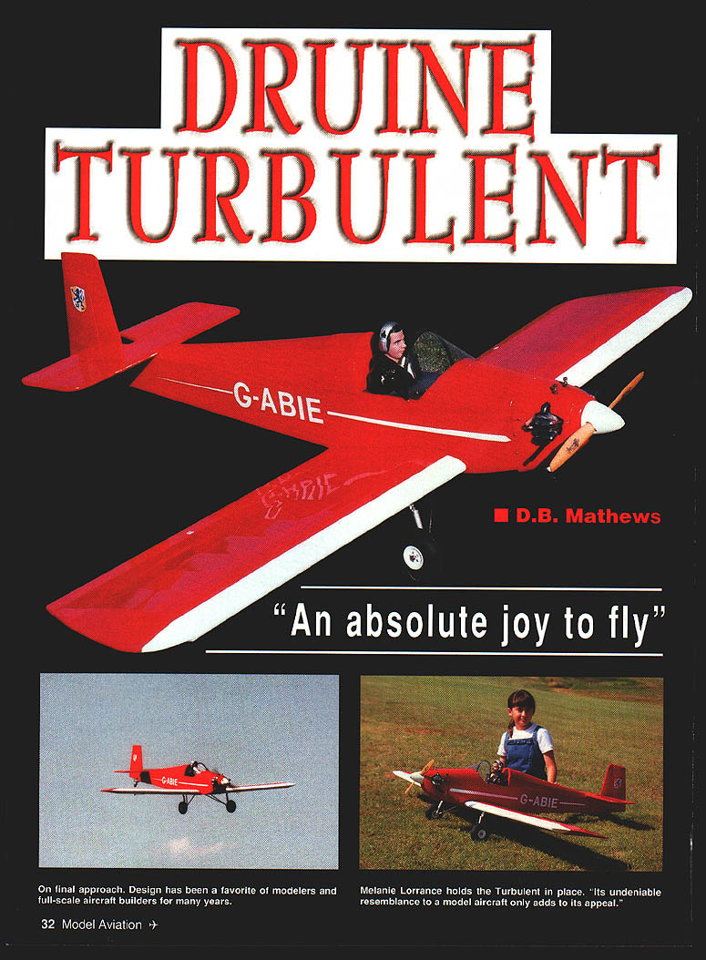
Druine Turbulent: "An absolute joy to fly"
D.B. Mathews
Ever wonder why some full-scale aircraft are repeatedly chosen as modeling subjects while others are rarely developed? A wide and diverse group of motivations is at work — from a desire to recreate longtime personal favorites to the comfort found in having seen certain scale models fly well.
The French-designed Druine Turbulent lacks the macho appeal of a warbird or the spectacular colors and aerobatics of contemporary acrobatic prototypes, but it is undeniably long on simplicity and diminutive size. Its resemblance to a model aircraft only adds to its appeal.
The Turbulent's popularity as a modeling subject likely ties directly to its long-running popularity with full-scale home-builders worldwide, particularly in England and France. It has relatively simple all-wood construction, minimal welded tubing or sheet metal, and excellent aerodynamics.
Designed in 1950 around readily available war-surplus air-cooled Volkswagen engines of only 36 hp, Turbulents are very small: 21.5 ft span and 17.3 ft length. Yet they cruise at about 87 mph and will climb at 450 fpm, with a gross weight of 620 lb.
As a scale subject, the Turbulent's long fuselage moments, wide-stance gear placement, and constant-chord wing are nearly ideal. The model presented here is similarly stable and lands as nicely as comparable sport designs. It is mildly acrobatic yet very easy to fly and land. By holding down the all-up weight, using the scale dihedral, and keeping power moderate, it is an absolute joy to fly.
Construction
The Turbulent was designed for modelers with some previous experience building from plans. Although it flies gently enough for a newcomer, construction is a bit advanced for that experience level. The instructions below cover aspects peculiar to this project; general building techniques are assumed.
Materials and hardware
- All materials and hardware are stock and can be obtained from a local hobby shop or by mail-order.
- Balsa: choose to match intended use — light C-grain for formers, medium C-grain for fuselage sides, light A-grain for planked areas.
- Plywood: birch aircraft-grade hardwood.
- Wing spars: long-grain Sitka spruce; basswood may be substituted if necessary.
- Adhesives: medium cyanoacrylate (CyA) for primary assembly; epoxy for high-stress areas (landing gear, engine attachment).
- Landing-gear blocks: stock Sig items.
- Tailwheel bracket hardware: Goldberg/Klett GD-23; tiller cut in half and mounted with 2-56 bolts and nuts.
- Empennage hinges: molded-and-pinned type such as Du-Bro 117. Laminated or piano-type hinges may be used for the ailerons where appropriate.
- Shock absorbers: stock RC car units (add realism; not critical to handling).
- Pilot figure: prepainted pilot from MGA Pilots (Fresno, CA) or local dealer.
- Instrument panel: preassembled unit from Midwest Products (#1099), adapted by trimming the corners to fit.
Powerplant
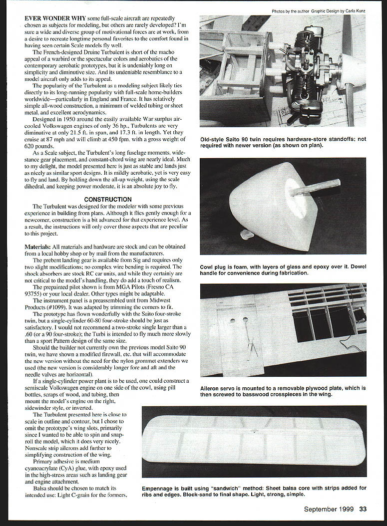
- The prototype flew well with the Saito four-stroke twin. A single-cylinder .60–.80 four-stroke should be satisfactory.
- Do not recommend a two-stroke single larger than .60 (or a .90 four-stroke); the Turbulent is intended to fly much more slowly than a sport-pattern design of the same size.
- The plans show a modified firewall to accommodate newer, longer engine versions without nylon grommet extenders.
- If using a single-cylinder engine, a semiscale Volkswagen mockup may be constructed on one side of the cowl (pill bottles, scrap wood, tubing) and the actual engine mounted sidewinder-style or inverted.
Scale details and simplifications
- The model is close to scale in outline and contour, but wing slots were omitted to allow spins and snap-rolls. Nonscale strip ailerons simplify wing construction.
- Primary finishes are film coverings; painted areas use polyurethane.
Tail feathers (empennage)
- Construct tail surfaces using the "sandwich" technique: a sheet balsa core with strips added for ribs and edges, then block-sanded to final airfoil/taper.
- This method yields light, strong, and accurate surfaces and is simpler than building a rib framework and skimming with sheet.
- Use #100 paper to rough out the shape, then finer grades to finish.
Tail assembly notes
- Cut hinge slots and install the elevator joiner before cutting out the rudder slot. Round exterior edges or bevel rudder/elevator faces for free movement.
- Because the fin/rudder is considerably wider at the base than the top, a wide bevel at the base is necessary.
- Elevator joiner: Sig SH-554 center-position horn (steel wire with molded and crimped nylon horn). The solder link should be wrapped with copper wire and soldered to prevent working loose.
- During final assembly, cut an access hole in the stab mount for the elevator horn. Reach down with hemostats to draw the outer portion of the Nyrod™ up through it. Attach the premeasured Du-Bro DU173 wire pushrod via a solder link to the elevator horn, then thread into the outer rod as the stab is epoxied to the tail mount. Use a threaded clevis on the servo end.
- Note: the fin's rear post runs down to the tailwheel mount. Do not bevel this portion; fill around it in the fuselage rear for a tight fit before permanently attaching it with epoxy after covering.
Fuselage
- The fuselage construction is based on techniques used by Gordon Whitehead for a 48-inch Turbulent published in RCM in 1977.
- Develop a kit of parts by transferring patterns to wood; photocopy parts, cut them out, and glue them to the wood with a glue stick.
- Drill all required holes before assembly.
- Precut sheet sides, balsa, and plywood doublers are installed after the strip framework in the rear areas has been completed.
- Block up the nose end and assemble the forward unit with epoxy to produce a smooth taper from F-3 to the firewall.
- Because the fuselage box top is flat from tail post to firewall, sides can be assembled over the top view using identical crossmembers and formers. Trial-assemble with masking tape and clamps, then run medium CyA along joints.
- Add the tailwheel plywood insert, cross-grained balsa bottom, and plywood in the tank area.
- Remove assembly from the plan, sand out roughness, then add turtledeck formers and stringers.
- For sheet-covered areas: adhere the bottom edge of one side to the fuselage box, spray the sheet with diluted ammonia and water, then pull the sheet down onto the formers and center strip using thick CyA. True the top edge with a metal straightedge and sharp knife, then repeat for the other half.
- The cockpit floor sits inside the box. Cut the cockpit coaming from balsa using a paper-folded pattern to get a mirror-image outline.
Wing
Ribs and layout
- Make copies of the ribs and adhere them to sheet stock with a glue stick. Stack-cut the ribs from the patterns. Be very accurate when cutting spar slots and holes for the aileron extension lines.
- Ribs that will have the plywood dihedral brace run through them should be pre-scored so they remain held together until the wing panels are joined to the center section.
Panel construction
- Build the wing flat on the work surface from the front spar back.
- Pin the lower trailing-edge sheet and aileron hinge spar, then position the lower spars with two ribs and install the center rib from the bottom up using a dihedral gauge.
- Attach the lower sheeting aft of the front spar and position/adhere the ribs using precut shear webs as guides. Note: the bottom rear shear has the aileron hinge spar on top of it, while the upper butt fits on top of the upper shear.
- Install the top spar and fit the upper sheeting. Fair and sand to section.
- Ailerons: cut from 3/32" sheet balsa, then contour to a taper on the top using a razor plane and sanding blocks.
- Aileron servos are mounted on a removable plywood plate screwed to basswood crosspieces in the wing.
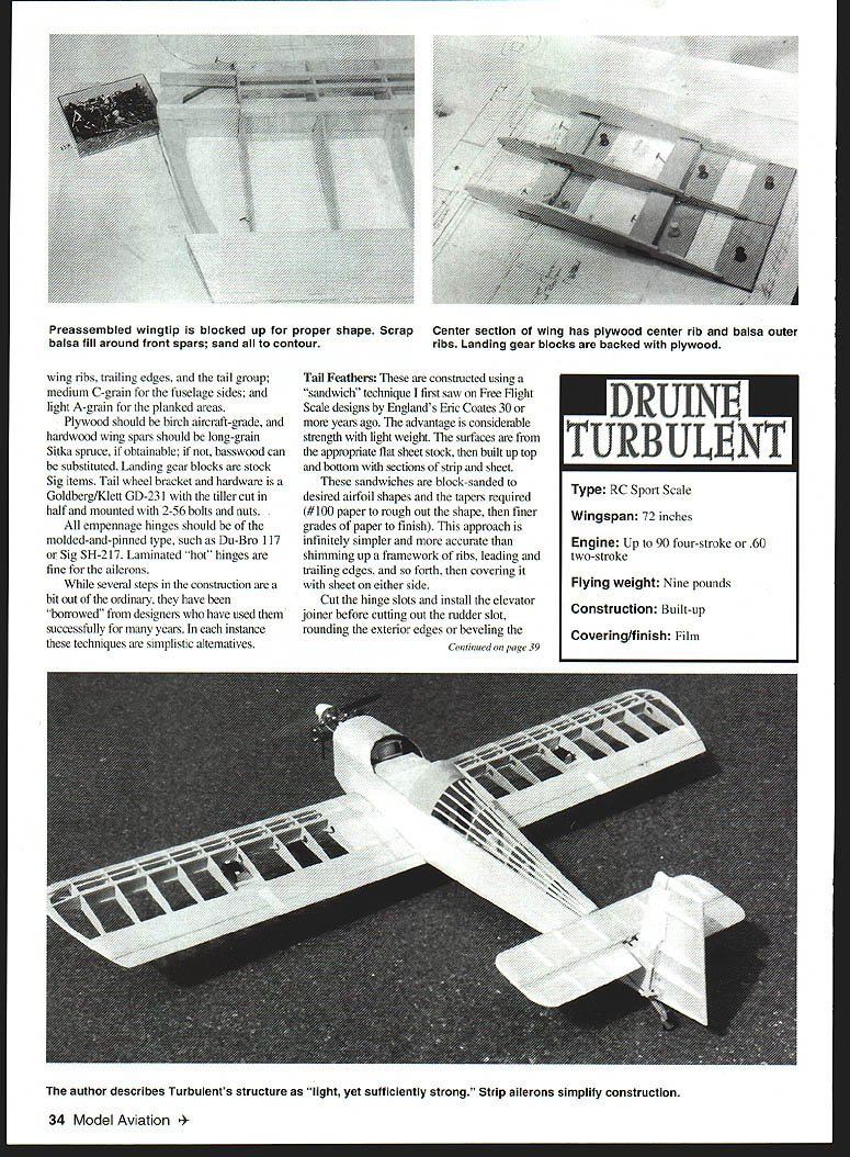
Wingtips and finishing
- Precut wingtips from medium C-grain stock and assemble flat. Add to the wing ends, install upper spars and center-section sheeting. Rear spars are cut at the matching angle, cracked, and pulled down onto the wingtip. Pull the sheet down onto the tip and use scrap balsa filler at the front spars. Sand to final contour; shape leading edge and aileron ends.
- Repeat to build the opposite wing panel.
Center section
- Assemble the center section independently from the wing panels. Cut balsa and plywood ribs, plywood floor sections, and landing-gear blocks.
- Assemble in the same sequence as wing panels, using epoxy. Ensure ribs are perpendicular to the surface.
- The dihedral brace is built integrally in two pieces that butt against the plywood center rib; it also serves as the rear brace for the wing dowels. Drill and install wing dowels after mating the wing to the fuselage.
- Add top sheeting and use scrap aileron material to fill above the bottom plywood sheet; sand to match.
- Block up each wing panel 1" at the outermost rib and final-sand the inside rib to be level with the table edge.
- Punch out pre-scored notches and slide the dihedral brace inside the panel with the panel blocked up and the center section held with weights. Smear epoxy on both rib faces and the dihedral brace, then slide together. Repeat for the opposite panel.
- After epoxy cures and sanding is completed, reinforce the two joints with 1" fiberglass tape and epoxy.
- Position and drill holes for the wing dowels (a 12" long 1/4" dowel is used). Check wing straightness relative to the tail post before drilling and tapping the blocks for 1/4-20 nylon wing bolts.
Cowl
- Fabricated using a white foam plug glued to the firewall and spinner backplate, cut to shape with a bread knife and coarse sandpaper.
- Apply three successive layers of 6-ounce glass cloth with Hobbypoxy II. Rough-sand each layer with #80 before adding the next.
- Final coat of Hobbypoxy is laid on, then an inflated balloon is pressed over it while slowly releasing air so it clings to the rear of the plug, producing a smooth outer surface requiring minimal filling and sanding.
- Cut the cowl vertically between the spinner and in front of the firewall, and horizontally in the middle of the cylinders.
- Use a "story stick" of scrap balsa to create a cutout pattern for cylinder heads and exhaust stacks; transfer to the cowl halves and cut with a carbide stone in a Dremel tool.
- Screw the cowl onto basswood blocks epoxied to the firewall. Epoxy plywood sections onto the bottom half of the cutout; hold the other half in place with sheet-metal screws.
- Air scoops: sections of plastic spoon epoxied over holes in the cowl. Top hole allows additional cooling air that exits through two holes in the cowl bottom. Allow clearance around cylinder cutouts to avoid overheating problems.
Landing gear
- Unit is from Sig's 1/4-scale Cub. Modification: bend the rear leg forward using a vise and large Vise-Grip pliers because the Turbulent gear is swept forward more than a Cub's.
- Crossbrace wires are not used.
- Joints are wrapped with soft copper wire and silver-soldered (using a propane torch) while the gear is temporarily attached to the center section with Sig SH-709 straps.
- RC car shock absorbers are functional but primarily decorative. Attach to the wing by plywood stubs adhered to the bottom spar and held with bolts and elastic stop nuts. Hold them behind the wheels with washers soldered fore and aft of their struts.
Covering and finish
- Scale Model Research (3114 Yukon Ave., Costa Mesa, CA) offers Foto-Paaks and scale three-views for decoration.
- After sanding and vacuuming, cover sections following the manufacturer's recommendation. Do not use heat-shrink plastics or fabrics on this model.
- Painted areas (cowl, etc.) were done in matching shades of Chevron Perfect polyurethane.
- The interior of the tank area should be coated with brushed-on epoxy before tank installation.
- Photo model numbers are die-cut sticky-backed vinyl from an office-supply store.
- Trim colors are UltraCote, ironed directly over the base color. UltraCote breathes and allows trapped air to escape when layering; minimal bubbling is a benefit.
Preflight
- With an Electrodynamics onboard glow igniter and its battery close to the firewall alongside the 1,200 mAh flight pack, the model required no nose weight to balance. However, add nose weight if needed to reach a safe balance point. Do not fly tail-heavy.
- Control throws called on the plans are close to optimum for mild aerobatics. Roll rate, loops (inside and outside), spins, and snap rolls are well-controlled and predictable with these settings.
- A slow, solidly reliable engine idle is imperative. At its relatively low wing loading the model is a floater and doesn't want to stop flying.
Flying
- The Turbulent is forgiving — it flies like a trainer. Takeoffs are simple: line up, add power, and watch it climb. No vicious tendencies.
- Wide-set main gear makes landings easy. Keep it level using 1/2 throttle on the base leg, then chop to idle on final descent. Three-point landings require a bit of up elevator released just before touchdown. Wheel landings are gentle as the Turbi settles onto its fat tires.
- Flight profile resembles a sport aerobatic model: long tail moment, rudder behind the elevator, and a semisymmetrical airfoil. It is not a wild, twitchy design — a scale sport aerobatic model that is fun and stable.
Druine Turbulent — Specifications
- Type: RC sport scale
- Wingspan: 72 inches
- Engine: up to 90 four-stroke or .60 two-stroke
- Flying weight: 9 pounds
- Construction: built-up
- Covering/finish: film
D.B. Mathews 909 N. Maize Rd., #734 Wichita, KS 67212
Transcribed from original scans by AI. Minor OCR errors may remain.

