
Dual Battery System
Jerry Smith
Radio installations that require lots of servos to control the model may experience their own unique form of glitching. This mod for receivers solves that problem and enhances system stability.
The problem
Do you fly giant-scale airplanes? Are you running multiple servos and experiencing some glitching from your radio? You may be short on battery power. Some modelers use six or seven servo functions and double up on servos for added safety. That can mean eight or nine servos in one airplane.
When the radio system is on, the servos sit at idle drawing a small, fixed current. When a stick on the transmitter is moved, one or several servos respond and draw significantly more current. This increased demand causes a momentary voltage drop to ripple through the entire system. The receiver, sensing the low voltage, temporarily loses sensitivity and can send a glitch to all the servos, producing a twitch at the control surfaces. This is more pronounced when the battery is on the flat part of the discharge curve.
The dual battery solution
The dual battery system provides a way around this problem by powering the receiver separately from the servos.
- The receiver is powered independently (it can use the original battery pack or a small pack of about 250 mAh or less since it draws very little current).
- The servos are powered with a hefty pack (for example, 1,500 mAh).
- Each power supply has its own switch and charging jack.
With this arrangement, when the servos draw large currents the receiver's independent power source is unaffected. Any slight voltage drop in the servo supply will not interfere with receiver performance, eliminating the glitching problem.
How to install the dual battery system
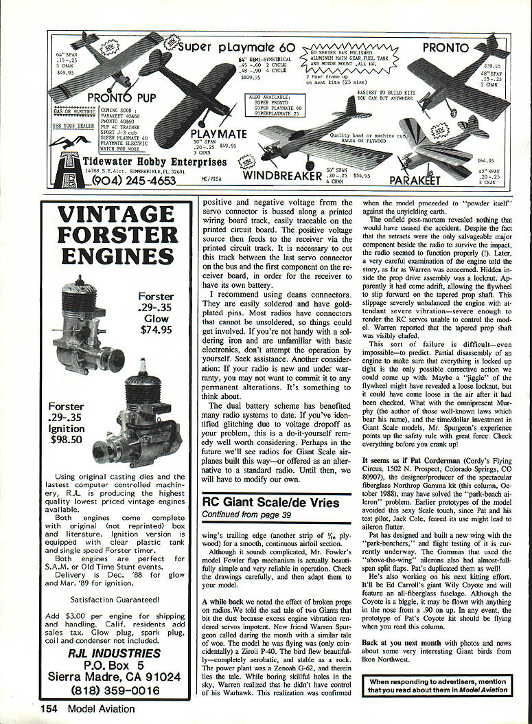
Making the dual battery system work requires adding leads and making a small modification to the receiver board.
- Add a positive and negative lead to the receiver and fit a connector so it can be supplied with its own battery.
- Generally, use the existing power connector on the receiver for the servo power supply.
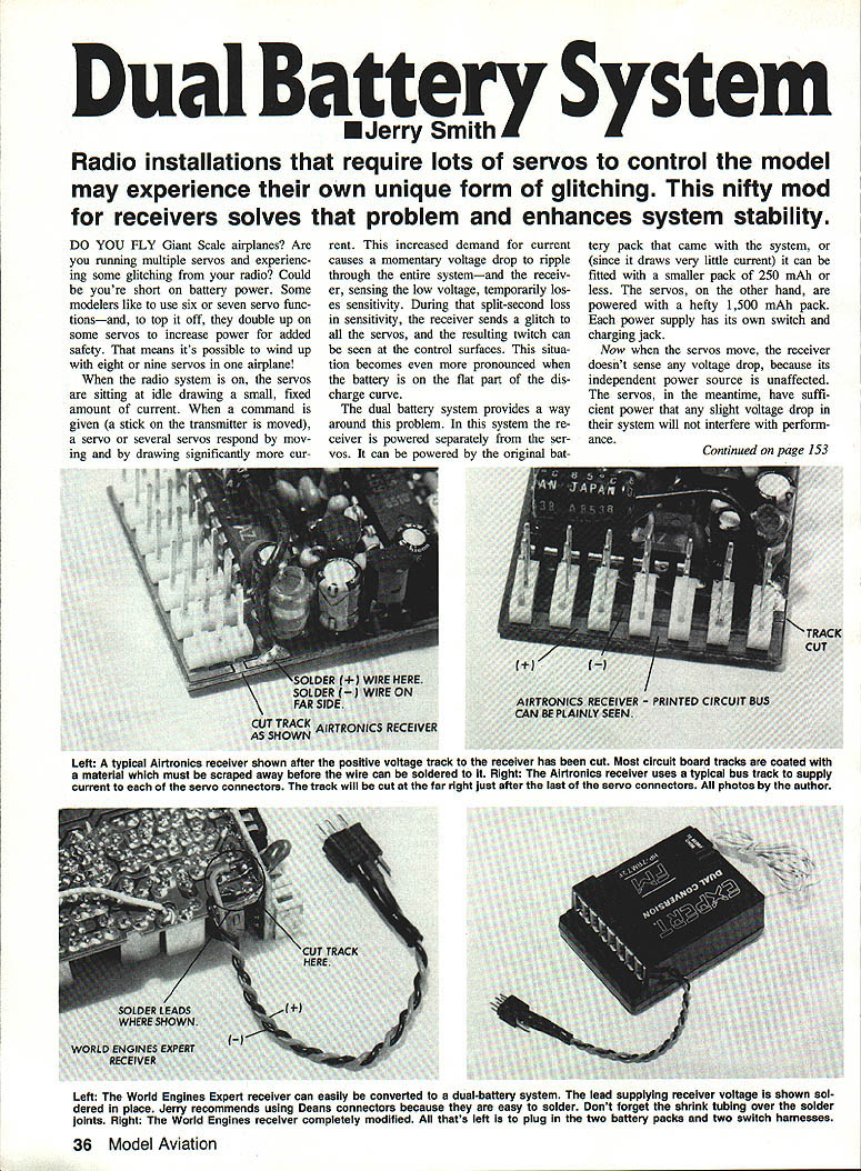
- On most receivers the positive-voltage track that feeds the servos is a common bus on the printed-circuit board; this track must be cut between the last servo connector on the bus and the first component on the receiver board so the receiver has its own battery.
- PCB tracks are often coated with a protective material. Scrape away the coating where you need to solder before attaching the lead.
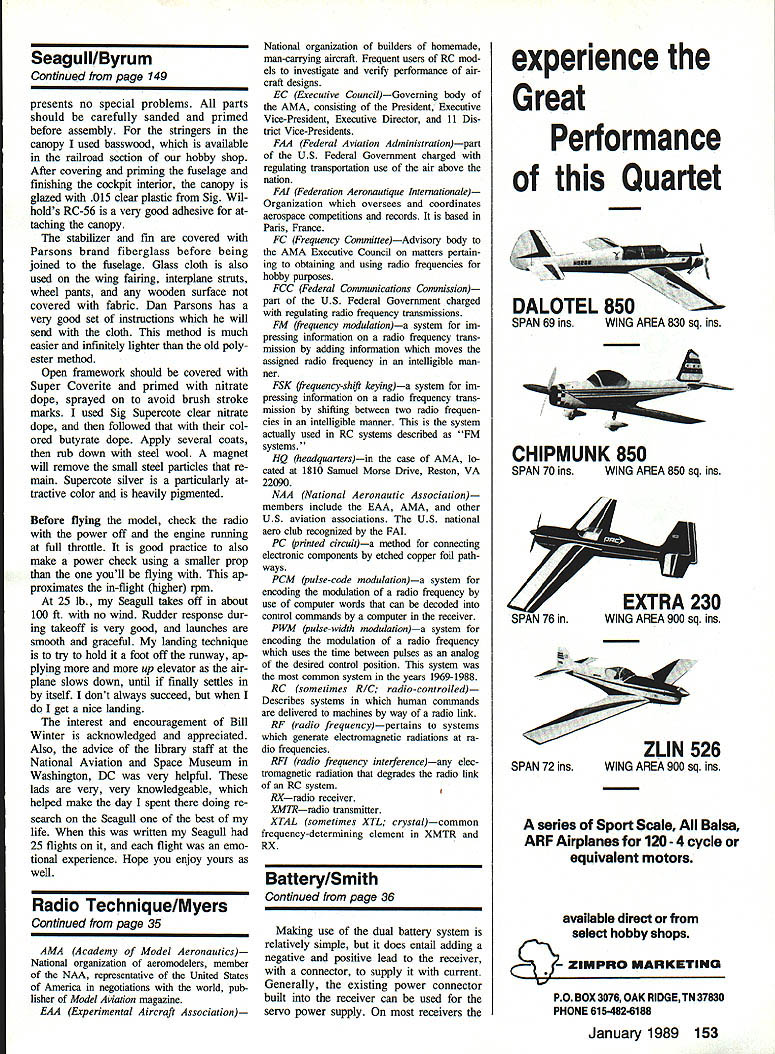
- On some receivers (for example, a typical Airtronics receiver) the common bus track is easily traceable and should be cut just after the last servo connector. Other models (for example, a World Engines Expert receiver) can be converted by soldering a lead to the receiver voltage supply point.
Recommendations and tips:
- I recommend using Deans connectors — they’re easy to solder and have gold-plated pins.
- Use heat-shrink tubing over the solder joints for insulation and strain relief.
- Many radios have connectors that are difficult or impossible to unsolder; the work can get involved.
- If you’re not handy with a soldering iron or unfamiliar with basic electronics, seek assistance.
- If your radio is new and under warranty, avoid permanent alterations until you consider the warranty implications.
Benefits and considerations
- Prevents servo current surges from causing momentary voltage drops at the receiver.
- Eliminates the glitching problem caused by supply voltage sag.
- A relatively simple do-it-yourself remedy if voltage drop is identified as the cause of glitches.
Perhaps in the future we’ll see radios for giant-scale airplanes built this way or offered as an option. Until then, modifying existing systems is an effective solution worth considering.
Transcribed from original scans by AI. Minor OCR errors may remain.

