
EAGLE 1
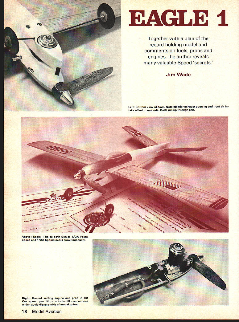
Together with a plan of the record holding model and comments on fuels, props and engines, the author reveals many valuable Speed 'secrets.'
Jim Wade
Eagle 1 holds both Senior 1/2A Proto Speed and 1/2A Speed records simultaneously.
IT WAS IN 1974 two so-called "unachievable" Speed records were reached — the 200-mph barrier in C-jet and the 100-mph mark in Proto. The author has devoted the last two years to breaking the 100-mph barrier in Proto. The pieces finally fit together. On December 1, 1974 Eagle set a new Senior Proto record, 101.48 mph, surpassing the existing record, 98.64 mph, set by the same airplane earlier in the year. Eagle now has the distinction of being the first Proto age classification to break the 100-mph mark officially. The left-hand propeller held the Proto record. The Senior Speed record, 108.27 mph, didn't seem to be accelerating fast enough on the first lap. So prop blade area was tried — the hunch paid off; the new prop was three mph quicker and set the record. Left-hand props seem to be the accepted standard in Proto; current Proto records (Jr., Sr., Op.) were set with left-hand props. At the time of writing this article I will cover what I call Speed "secrets."
Apparently people agree that giving out speed "secrets" is okay — that's the way we got started. Someone cared enough to let us use years of experience. I've been fortunate enough to have some respected names in speed circles — Dale Kim, Jim Nightingale, John Newton, Jerry Thomas, Jerry Bradshaw — help get me started and contribute ideas.
Main considerations in the design of Eagle 1:
- Light weight — quickest out of the starting gate wins. Proto Speed events take light airplanes under five ounces. Eagle weighs 4 oz.
- Smooth flying characteristics — anything other than straight level flight will slow you down.
- Durable — the way to find out how certain variables such as props, fuels and engine changes will affect Proto speed is to try them in the air, which means lots of test flights.
- Simple, functional — that's key to being able to duplicate performance. If something goes wrong you should be able to find the problem quickly and fix it.
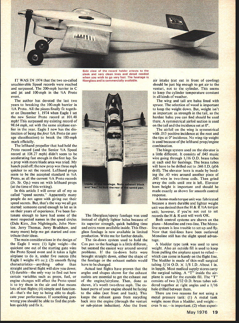
A fiberglass/epoxy fuselage was used instead of slightly lighter balsa because of its superior strength, quick building time and the extra room available inside. Fiberglass fuselages are now available in limited production.
Further details: The tie-down system used to hold the Cox pan to the fuselage is a little different. It seemed the easiest way around several problems. Tie-down bolts are brought straight down through the pan. Actual test flights have proven the angles and shapes shown. Exhaust outlets are essential to get exhaust out of the engine/airplane; once done, it's worth two to three mph. Exhaust ports should face to the sides, not front or back, to keep exhaust gases from recycling back into the engine through the venturi (sub-piston induction). Also, the front air intake cut out in the front cowling should be just big enough to get air to the venturi. This seems to keep the cylinder temperature constant in all kinds of weather.
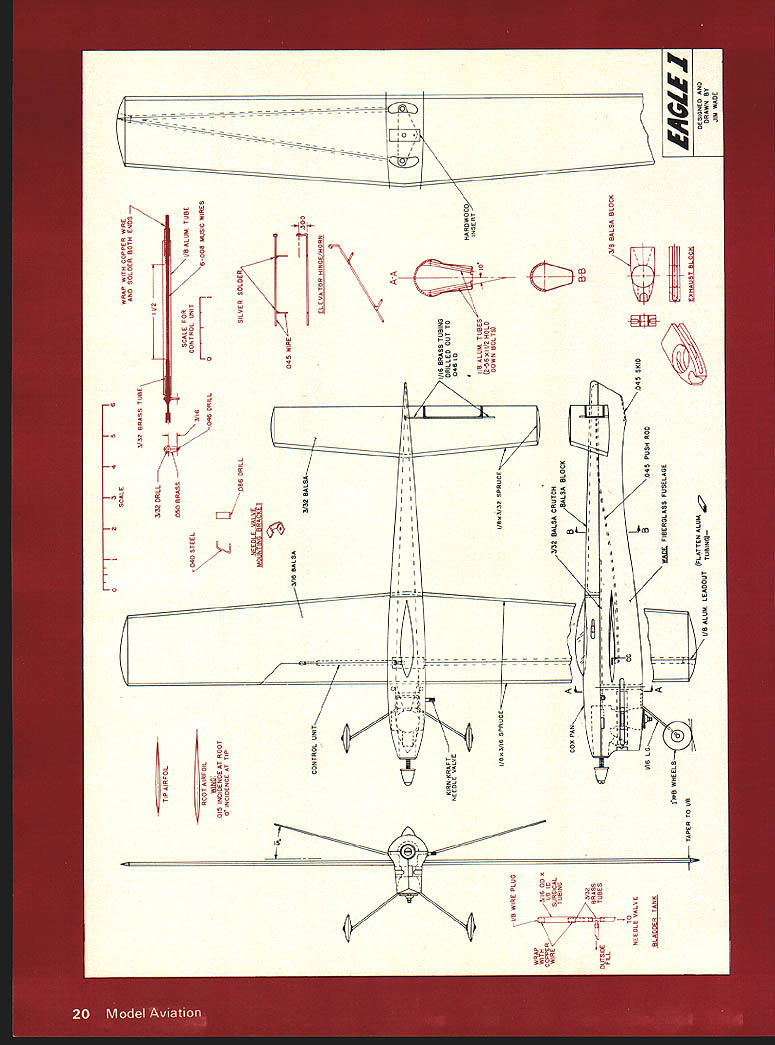
Wing and tail: balsa lined with spruce. Selection of wood is important to keep weight down. Where strength is important, weight isn't as critical; the tail should be built from the hardest balsa you can find. A symmetrical airfoil section is used for the tail. Tail incidence is set at 0°. The wing airfoil is symmetrical with .015° positive incidence at the root and 0° at the tips. No wing-tip weight is used because of the left-hand prop/engine combination.
The hinge system used on the elevator is a little different. It consists of .045" music wire going through 1/16" OD brass tubes as end bushings. The brass tubes should be drilled out to .046" ID with a #56 drill. The elevator horn is made by bending .045" wire around another piece of .045" wire with two or three coils; grind away coils until left as shown. Elevator horn height is important and should be made exactly as shown for smooth control response.
A home-made torque unit was fabricated because a durable, lighter-weight unit was desired. If you're out to set records, the H & R torque unit will work OK. Both control systems are shown on the plans. Monoline is less trouble to set up and fly. Now that tied-lines have outlawed monoline, it still has a slight speed advantage.
A bladder-type tank is used to save weight. Also, an outside fill used to avoid pulling the airplane apart to refuel can come in handy on the flight line. The bladder is made from thin-wall surgical tubing 3/16" OD x 1/8" ID. About 1 inch in length. Most medical supply stores carry the surgical tubing. A "T" inside the airplane is used for outside fill. The "T" consists of two 3/32" O.D. brass tubes soldered together at right angles and a 1/16" hole drilled between them.
There are two reasons for not using a metal pressure tank: (1) A metal tank weighs more than a bladder, and weight—even 1/2 oz.—is important; (2) when experi-menting with different pressures and fuels the bladder is more forgiving and easier to change.
Also the front air intake (cut out in front of cowling) should be just big enough to get air to the venturi, not to the cylinder. This seems to keep the cylinder temperature constant in all kinds of weather.
The wing and tail are balsa lined with spruce. The selection of wood is important to keep the weight down. But, weight isn't as important as strength in the tail, so the hardest balsa you can find should be used there. A symmetrical airfoil section is used on the tail and the incidence set at 0°.
The airfoil on the wing is symmetrical with .015° positive incidence at the root and the tips at 0° incidence. No wing-tip weight is used because of the lefthand prop/engine combination.
The hinge system used on the elevator is a little different. It consists of .045" music wire going through 1/16" O.D. brass tubes as end bushings. The brass tubes will have to be drilled out to .046" I.D. (#56 drill). The elevator horn is made by bending the .045" wire around another piece of .045" wire in two to three coils. Then grind away the coils until only the horn remains. Elevator horn height is important and should be made exactly as shown for smooth control response.
A home-made torque unit was fabricated because a more durable, lighter-weight unit was desired. If you're out to set records, the H & R 1/2A torque unit will work OK. Both control systems are shown on the plans—Monoline and two-line. The Monoline system is less trouble to set up and fly. Monoline still has the slight speed advantage.
A bladder-type tank was used to save weight. Also an outside fill is used to keep from pulling the airplane apart to refuel—can come in handy on the flight line. The bladder is made from thin-wall surgical tubing 3/16" O.D. x 1/8" I.D. About 1" in length. Most medical supply stores carry the surgical tubing. A "T" inside the airplane is used for outside fill. The "T" consists of two 3/32" O.D. brass tubes soldered together at right angles and a 1/16" hole drilled between them.
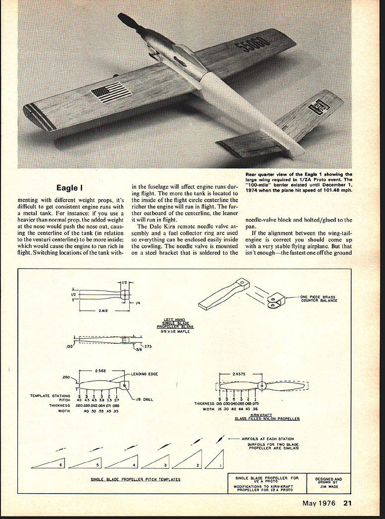
There are two reasons for not using a metal pressure tank: (1) A metal tank weighs more than a bladder, and weight—even 1/2 oz.—is important; (2) when experi- No continuable article text on this scanned page — it contains only the Eagle 1 plans/diagrams. Experimenting with different weight props, it's difficult to get consistent engine runs with a metal tank. For instance: if you use a heavier than normal prop, the added weight at the nose would push the nose out, causing the centerline of the tank (in relation to the venturi centerline) to be more inside; which would cause the engine to run rich in flight. Switching locations of the tank within the fuselage will affect engine runs during flight. The more the tank is located to the inside of the flight circle centerline the richer the engine will run in flight. The further outboard of the centerline, the leaner it will run in flight.
The Dale Kirn remote needle valve assembly and a fuel collector ring are used so everything can be enclosed easily inside the cowling. The needle valve is mounted on a steel bracket that is soldered to the needle-valve block and bolted/glued to the pan.
If the alignment between the wing-tail-engine is correct you should come up with a very stable flying airplane. But that isn't enough—the fastest one off the ground and flying smooth will still be the winner. So anything you can do to achieve that will help (but not without many hours in the practice circle with a pylon).
That covers the airplane fabrication part.
Props, Fuel and Engine
All Cox T.D. .049 engines are created equal. But, some are more equal than others. A few simple modifications and some time spent checking some critical areas can turn your run-of-the-mill production engine into an all-out record-setting engine.
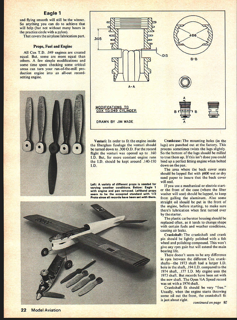
Venturi: In order to fit the engine inside the fiberglass fuselage the venturi should be turned down to .300 O.D. For the record flight the venturi was opened up to .160 I.D. But, for more constant engine runs the I.D. should be kept around .140-.150 I.D.
Crankcase: The mounting holes (in the lugs) are punched out at the factory. This process sometimes twists the lugs slightly. So the bottom of the lugs should be milled to true them up. If this isn't done you could bind up a perfect fitting engine when bolted down on the pan.
The area where the back cover seats should be lapped flat with #400 wet or dry sand paper to insure that the back cover will seal.
If you use a mechanical or electric starter the front of the case (where the fiber washer will seat) should be lapped, to keep from galling the aluminum. Also some straight oil should be put in the front of the engine, before starting, to make sure there's lubrication when first turned over by the starter.
The plastic carburetor housing should be replaced often, as it tends to change shape with certain fuels and weather conditions, causing air leaks.
Crankshaft: The crankshaft and crank pin should be lightly polished with a felt wheel and polishing compound. This won't give any rpm gain but will extend the main bearing life.
There doesn't seem to be any difference in rpm between the different Cox crankshafts—the 1973 shaft had a larger I.D. hole in the shaft, .194 I.D. compared to the 1974 shaft, .177 I.D. My engine uses the 1973 shaft. But records have been set with the new shaft. The Open 1/2A Speed record was set with a 1974 shaft.
Crankshaft fit should be very "free." Usually, when the engine starts throwing some oil out the front, the crankshaft fit is just about right.
Transcribed from original scans by AI. Minor OCR errors may remain.

