
Eaglerock
Frank Beatty
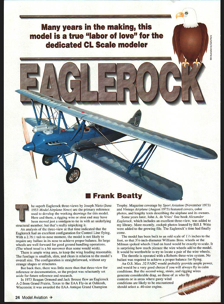
Many years in the making, this model is a true "labor of love" for the dedicated control-line scale modeler.
The superb Eaglerock three-views by Joseph Nieto (June 1953 Model Airplane News) were the primary reference used to develop the working drawings for this model. Here and there, a rigging wire or strut end may have been moved just a smidgen to tie in with an underlying structural member; but that's really nitpicking.
An analysis of the three-view indicated that the Eaglerock had an excellent configuration for control line flying. With a 2.76:1 tail-to-nose moment, the model is not likely to require any ballast in its nose to achieve proper balance. Its large wheels are well forward for good ground handling operations (wheel tread is a bit narrower than some would wish). There is ample wing area to keep wing loading reasonable. The fuselage is smallish, slim, and clean in relation to the model's overall size; the configuration is straightforward without any strange shapes or structures.
But back then there was little more than that three-view for reference, so the project was reluctantly set aside for future research.
In 1973 Reagan Ormond and Jack Brouse flew an Eaglerock A-2 from Grand Prairie, Texas, to the EAA Fly-In at Oshkosh, Wisconsin; it was awarded the EAA Antique Grand Champion Trophy. Magazine coverage by Sport Aviation (November 1973) and Vintage Airplane (August 1973) featured color photos and lengthy articles describing the airplane and its owners.
Some years later, John A. de Vries' book Alexander Eaglerock, which includes an excellent three-view, was added to my library. More recently, cockpit photos loaned by Bill J. Witte were added to the growing file. The Eaglerock's time had finally come.
The model has been built to an odd scale of 1 1/3 inches to the foot so that 3 5/8-inch-diameter Williams Bros. wheels or the Milman spoked wheels I had on hand would be exactly to scale. It is surprising how much pizzazz the wire wheels add to the model. It would be worthwhile to try to locate a pair of the wire wheels.
The throttle is operated with a Roberts three-wire system. No ballast was required to achieve proper balance for flying. An O.S. Max .32 FABC would probably provide ample power for calm conditions, but the second wing, struts and rigging wires generate considerable drag. For contest flying or gusty conditions, select a .40-size engine. A .40 flies the model with spirit and can bull its way through gusts. Touch-and-goes and snap ground handling are very good. The Eaglerock can be taxied tail-up indefinitely on its two wheels.
History
The aircraft industry has often experienced roller-coaster periods of growth and decline. World War I stimulated technical advances and growth in the industry; but after the war, development of commercial aviation was dampened by the huge numbers of surplus aircraft sold at fire-sale prices.
It was in this era that the Alexander Aircraft Company introduced a new biplane: the Eaglerock. In the early 1920s, J. Don Alexander, president of a film company, was using "aerial salesmen" to fly between appointments. Building airplanes was a natural next step. Alexander persuaded his brothers to get into the airplane-making business in 1924. An airplane was designed, manufacturing facilities were set up, and a network of distributors established.
The Eaglerock proved popular with small operators and flying schools. Even though plant facilities were expanded, production struggled to meet demand until the stock market crash of October 1929 and the Great Depression. Aircraft sales fell dramatically. The company tried desperate measures but closed on August 5, 1932. In seven years it had produced almost 1,300 airframes, nearly 900 of which were Eaglerock biplanes.
Very few Eaglerocks have survived. Many were worn out, stored and rotted away, or used as crop dusters. Some were used in movie crash sequences; film producers were not shy about mixing airplane types in sequences. Examples of Eaglerocks appear in films such as Central Airport and The Flying Irishman.
— Frank Beatty
Construction
This is a biplane—lots of struts, rigging wires, false ribs, and other detailing. It is a long-time, all-winter labor-of-love if you go the extra mile. The model has been broken down into subassemblies. Jigs, strut locator blocks, predrilled pilot holes and lower wing spar alignment boxes are used temporarily to locate and align wings and struts while assemblies are built in place. Once built, assemblies are taken apart to simplify covering, painting, polishing and detailing. Parts should automatically fall into proper alignment when reassembled. The undercarriage and tail surfaces are built first; fuselage work is delayed until jigs and fixtures are required.
Undercarriage
- Bend 1/8" diameter music wire main struts and fit to a 3/32" plywood mounting plate.
- Fashion a simple jig to locate and lock axles in the proper fore-and-aft position relative to the plywood platform.
- Bend up, fit, bind with fine wire, and solder the other struts in place.
- Install fiberglass or balsa strut dummy shock absorber fairings now rather than after the assembly is permanently mounted to the fuselage.
- Fit maple engine mounts into place. Locate, drill, and set all bellcrank and engine blind mounting nuts in these beams. Install the 1/8" plywood engine mount to firewall reinforcing gussets now.
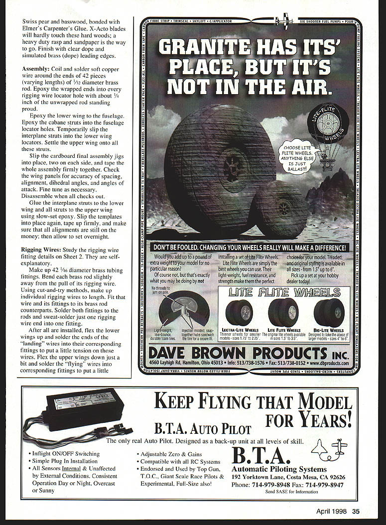
Make up two 3/32" sheet balsa cabane strut erection jig templates using the pattern on the plans. Cement these jigs to the top of the fuselage sides. Draw centerlines on two 3/8" x 1/2" x 10" pieces of balsa. Measure 3-3/4" from these centerlines and mark cabane strut pilot hole locations. Drill 1/16" holes through these spars and elongate the holes in the forward spar to about 3/32" x 3/32". Align and epoxy these spars into the cabane erection jigs. The 1/16" wire can be cut up and fitted between the locator holes on the bulkheads and those in the dummy spars.
Fit balsa fairings to these struts. If the fairings are accurately butted against the bottom surfaces of the dummy spars now, the upper wing center section will be automatically located when fitted to the cabane struts later. The jigs can then be removed.
Continue fuselage construction by cementing all longerons, stringers, wing root fairing blocks, and stabilizer outline framing members to the fuselage sides. Add 1/8" plywood, leadout wire, elevator pushrod wire, and dummy rudder and elevator control wire guides. Make the brass throttle reverse-travel crank and install. Bolt the engine and bellcrank (with leadouts installed) into place. Slide the stabilizer into its slot and pin firmly in place.
Make up all throttle and elevator pushrod wire linkages. Check for smooth, nonbinding operation. Solder all linkage connections except those at the carburetor crank and elevator horn. The engine and tail surfaces can be removed and set aside. Locate and epoxy the fuel tank into position. Epoxy the tail skid assembly into position. Epoxy balsa triangular strip reinforcing gussets to fuselage sides and bulkheads 2 and 3, then epoxy the undercarriage assembly platform against these. Various balsa blocks and two 1/8" x 1/8" basswood stringers will finish the fuselage bottom. Cement the 1/16" x 1/8" basswood turtledeck stringers and balsa tail cone fairing to the fuselage top.
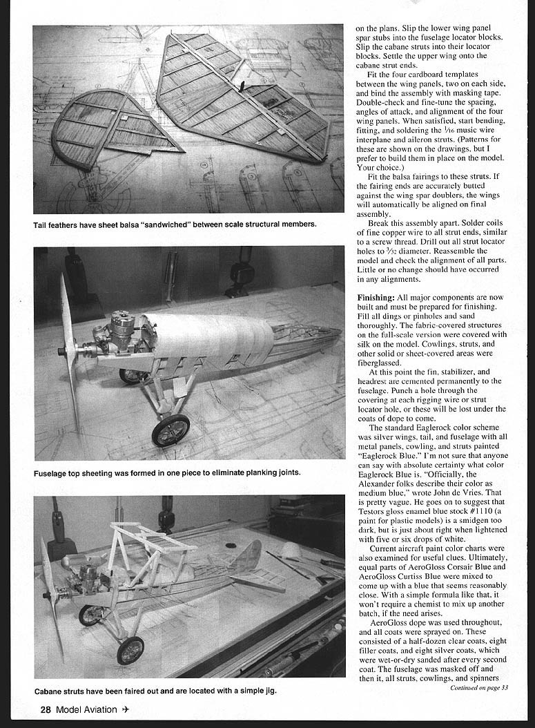
Stabilizer and Elevators
- Cut 1/16" sheet balsa cores for stabilizer and elevators.
- Soak four 1/16" x 3/16" balsa strips in ammonia and bend around the stabilizer leading edge; when dry, cement to the core.
- Cement the remainder of the balsa frames and ribs to the cores.
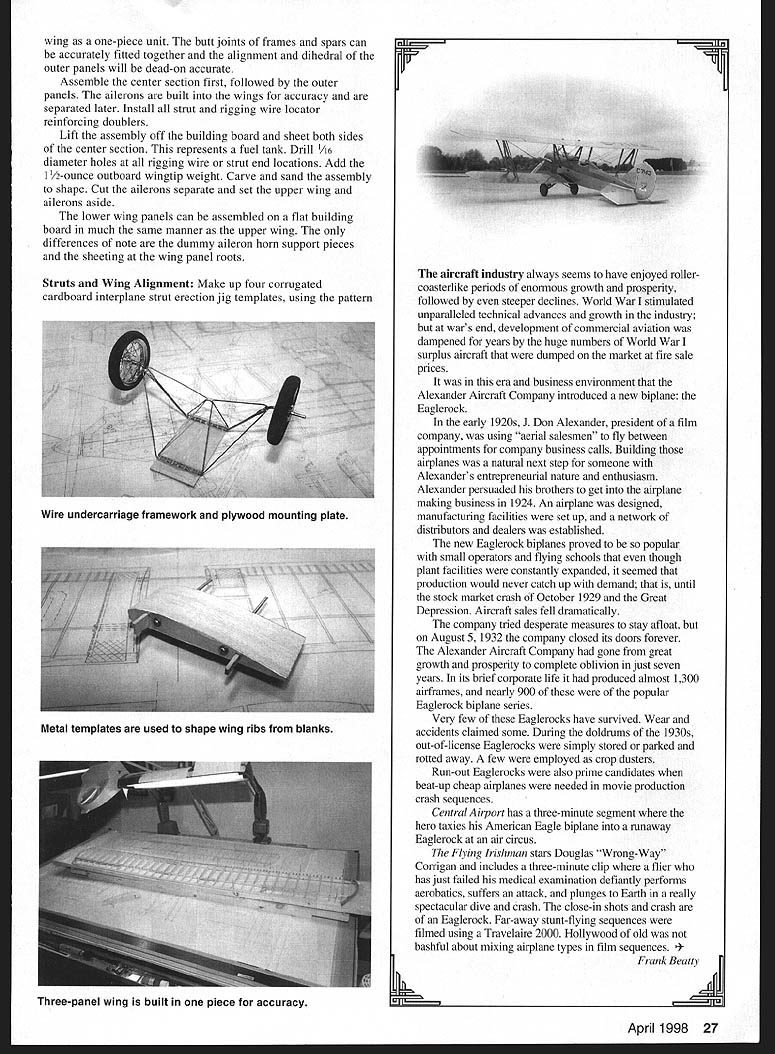
- Install the elevator horn, tubing and wire hinge system.
- Add hardwood rigging-wire mounting blocks.
- Sand assemblies and set aside.
Fin and Rudder
Fin and rudder structures are built in the same manner as the stabilizer and elevators.
Cockpit Choices
- Decide whether to install detailed cockpits (Precision Scale) or platforms for dummy pilots (Sport Scale). The author opted for platforms.
- Finish the platforms and visible portions of bulkheads 4–6. Make and install instrument panels.
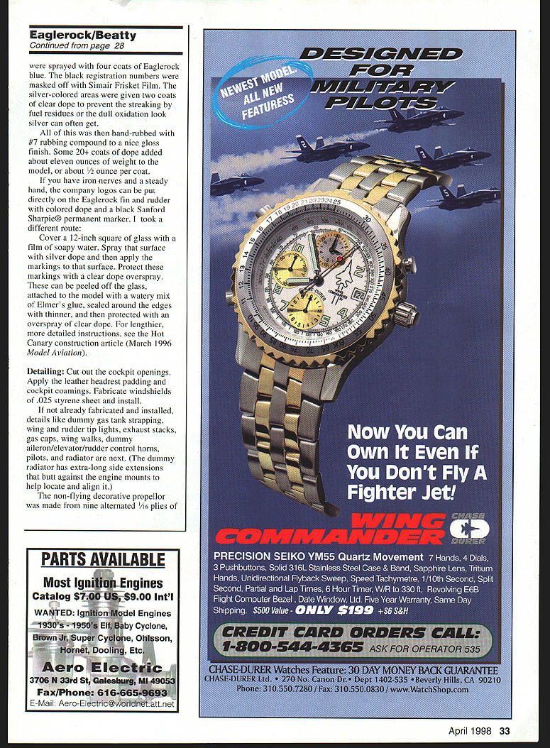
- Soak a 1/8" x 7" x 12" balsa sheet in ammonia and bend it over the fuselage top to form cockpit decking. When dry, remove, finish inside surface, then fit and glue to the fuselage in two pieces (split down the center). Wait until painting and finishing are complete before cutting out cockpit openings.
Cowlings
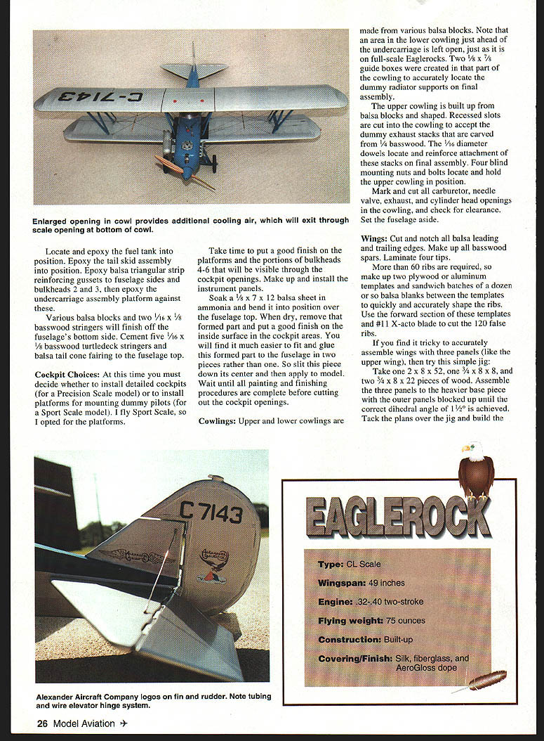
- Build upper and lower cowlings from balsa blocks. Leave an open area in the lower cowling just ahead of the undercarriage, as on full-scale Eaglerocks.
- Create two 1/8" x 5/8" guide boxes in that part of the cowling to locate dummy radiator supports on final assembly.
- Recessed slots accept dummy exhaust stacks carved from 1/4" basswood. Use 1/16" dowels to locate and reinforce attachment of these stacks on final assembly. Four blind mounting nuts and bolts hold the upper cowling in position.
- Mark and cut carburetor, needle valve, exhaust, and cylinder head openings and check clearance.
Wings
- Cut and notch all balsa leading and trailing edges. Make all basswood spars and laminate four tips.
- More than 60 ribs are required; make two plywood or aluminum templates and sandwich batches of balsa blanks between the templates to quickly and accurately shape ribs. Use the forward section of these templates and a #11 X-Acto blade to cut 120 false ribs.
- If assembling a three-panel wing (upper wing) is tricky, use this simple jig:
- Take one 2" x 8" x 52" board, one 3/4" x 8" x 8" piece, and two 3/4" x 8" x 22" pieces. Assemble the three panels to the heavier base piece with the outer panels blocked up until the correct dihedral of 1.5° is achieved. Tack the plans over the jig and build the wing as a one-piece unit. Butt joints of frames and spars can be accurately fitted and the dihedral of the outer panels will be accurate.
- Assemble the center section first, followed by outer panels. Build ailerons into the wings for accuracy and separate them later. Install all strut and rigging wire locator reinforcing doublers.
- Lift the assembly off the building board and sheet both sides of the center section (this area represents a fuel tank). Drill 1/16" holes at all rigging wire or strut end locations. Add 1.5-ounce outboard wingtip weight. Carve and sand the assembly to shape. Cut and set the ailerons aside.
- Lower wing panels can be assembled on a flat building board similarly, with differences in dummy aileron horn supports and sheeting at wing panel roots.
Struts and Wing Alignment
- Make four corrugated cardboard interplane strut erection jig templates using the pattern on the plans.
- Slip the lower wing panel spar stubs into the fuselage locator blocks. Slip the cabane struts into their locator blocks. Settle the upper wing onto the cabane strut ends.
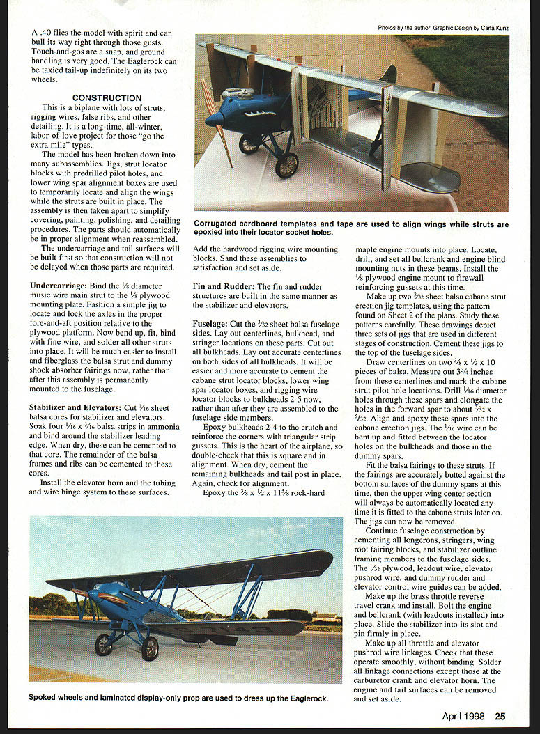
- Fit the four cardboard templates between the wing panels, two on each side, and bind the assembly with masking tape. Double-check spacing, angles of attack, and alignment of the four wing panels.
- When satisfied, bend, fit, and solder the 1/16" music wire interplane and aileron struts. (You may prefer building them in place on the model.)
- Fit balsa fairings to these struts; if fairing ends are accurately butted against wing spar doublers, wings will automatically align on final assembly.
- Break the assembly apart. Solder coils of fine copper wire to all strut ends (like screw threads). Drill out all strut locator holes to 3/32" diameter. Reassemble and check alignments; little or no change should have occurred.
Finishing
- Prepare all major components: fill dings/pinholes and sand thoroughly.
- The fabric-covered structures on the full-scale were silk; the model used silk covering. Cowlings, struts, and other sheet areas were fiberglassed.
- Cement fin, stabilizer, and headrest permanently to the fuselage. Punch a hole through the covering at each rigging wire or strut locator hole or these will be lost under coats of dope.
- Standard Eaglerock color scheme: silver wings, tail, and fuselage with metal panels, cowling, and struts painted "Eaglerock Blue." The exact shade is unclear; John de Vries suggested Testors gloss enamel blue stock #1110 lightened with five or six drops of white. The author mixed equal parts AeroGloss Corsair Blue and AeroGloss Curtiss Blue for a close match.
- AeroGloss dope was used throughout, sprayed on in coats: about six clear coats, eight filler coats, and eight silver coats, wet-or-dry sanded after every second coat. Fuselage, struts, cowlings and spinners received four coats of Eaglerock blue. Black registration numbers were masked with Simair Frisket Film. Silver areas were given two coats of clear dope to prevent fuel streaking or dull oxidation.
- Hand-rub with #7 rubbing compound to a nice gloss. Some 20+ coats of dope added about 11 ounces of weight to the model (≈1/2 ounce per coat).
- For company logos: cover a 12" square of glass with soapy water, spray silver dope, apply markings, protect with clear overspray. Peel off, attach to the model with watery Elmer's glue, seal edges with thinner, and protect with clear dope overspray.
Detailing
- Cut out cockpit openings. Apply leather headrest padding and cockpit coamings. Fabricate windscreens from .025" styrene sheet and install.
- Install details: dummy gas-tank strapping, wing and rudder tip lights, exhaust stacks, gas caps, wing walks, dummy control horns, pilots, and radiator. The dummy radiator has extra-long side extensions that butt against the engine mounts to help locate and align it.
- The non-flying decorative propeller was made from nine alternating 1/16" plies of Swiss pear and basswood, bonded with Elmer's Carpenter's Glue. Use a heavy-duty rasp and sandpaper to shape, finish with clear dope and simulated brass leading edges.
Assembly
- Coil and solder soft copper wire around the ends of 42 pieces (varying lengths) of 1/32" diameter brass rod. Epoxy the wrapped ends into every rigging wire locator hole with about 1/4" of unwrapped rod standing proud.
- Epoxy the lower wing to the fuselage. Epoxy cabane struts into the fuselage locator holes. Temporarily slip interplane struts into the lower wing locators and settle the upper wing onto all these struts.
- Slip the cardboard final assembly jigs into place (two on each side) and tape the whole assembly firmly together. Check spacing, alignment, dihedral angles, and angles of attack. Fine tune as necessary and disassemble when all checks out.
- Glue the interplane struts to the lower wing and all struts to the upper wing using slow-set epoxy. Slip templates into place again, tape up firmly, verify alignments, and allow to set overnight.
Rigging Wires
- Study rigging wire fitting details on the plans (Sheet 2).
- Make 1/32" diameter brass tubing fittings. Bend each brass rod slightly away from the pull of its rigging wire.
- Using cut-and-try methods, make up individual rigging wires to length. Fit each wire and its fittings to brass rod counterparts. Solder both fittings to the rods and sweat-solder just one rigging wire end into one fitting.
- After all are installed, flex the lower wings up and solder the ends of the "landing" wires into their corresponding fittings to put tension on those wires. Flex the upper wings down slightly and solder the "flying" wires into corresponding fittings to put tension on those wires. Snip off excess brass rod ends and file smooth. Leave fittings a bit long if you want to avoid separation.
- Rigging wire vibration dampeners: made from 1/16" diameter x 5/8" long brass rod bound to the rigging wires with button thread and CYA.
Flying
From the very first, the Eaglerock flew very steadily, with just a little fore-and-aft oscillation; ground handling was good. When first completed, the model's thrustline was level when suspended from the recommended balance point. The model tended to oscillate one to three times after elevator inputs, especially into gusts. Five ounces of lead was added to the nose, making the model hang nose-down about seven degrees; that corrected the oscillation.
Observers noted the model seemed to fly fast for a scale antique biplane. Switching from an 11" x 6" prop to an 11" x 5" slowed it to a more scale-like speed (on gusty days the 11" x 6" is preferred). The model has fairly light wing loading, ample lift, and landing approaches must be made at very slow speeds. The model will tend to roll out tail-up on the wheels until a touch of elevator is applied to get the tail on the ground. If taxed too fast into the wind, it may balloon back into the air.
The Eaglerock can be flown regularly during weekend sessions or be competitive on the contest circuit—now that's my kind of scale model.
Frank Beatty 2608 Pontoon Rd. Granite City, IL 62040
Transcribed from original scans by AI. Minor OCR errors may remain.

