
Eastbourne Monoplane
SCALE modelers always have a squadron of elusive "ideal subjects" that haunt them in their daydreams as well as their sleep. This time it was that "ideal vintage craft," and it kept me up many a night ravaging through my files. After a week of sleepless nights a friend drops by with an interesting three-view he's come across. Tearing it from his hands, ranting and raving, I descended into the depths of the model shop. The EAC was the result.
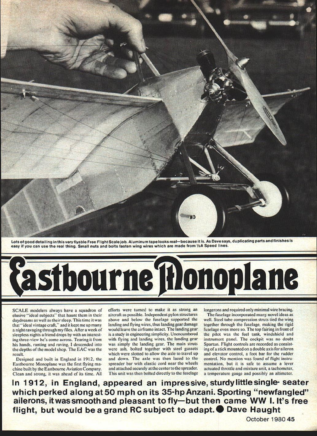
Designed and built in England in 1912, the Eastbourne Monoplane was the first flying machine built by the Eastbourne Aviation Company. Clean and strong, it was ahead of its time. All efforts were turned to make it as strong an aircraft as possible. Independent pylon structures above and below the fuselage supported the landing and flying wires, so that landing-gear damage would leave the airframe intact. The landing gear is a study in engineering simplicity. Unencumbered with flying and landing wires, the landing gear was simply the landing gear. The main struts were ash, bolted together with steel gussets which were slotted to allow the axle to travel up and down. The axle was then laced to the spreader bar with elastic cord near the wheels and attached securely at the center to the spreader. This unit was then bolted directly to the fuselage longerons and required only minimal wire bracing.
Fuselage and cockpit
The fuselage incorporated several novel ideas. Steel-tube compression struts tied the wing together through the fuselage, making the rigid fuselage even more so. The top fairing in front of the pilot served as the fuel tank, windshield and instrument panel. The cockpit was no doubt Spartan. Recorded flight controls consisted of a stick mounted on a double axis for aileron and elevator control and a foot bar for rudder control. No specific flight instrumentation was recorded, but it is reasonable to assume a lever actuated throttle and mixture unit, a tachometer, a temperature gauge and possibly an altimeter.
Empennage and control surfaces
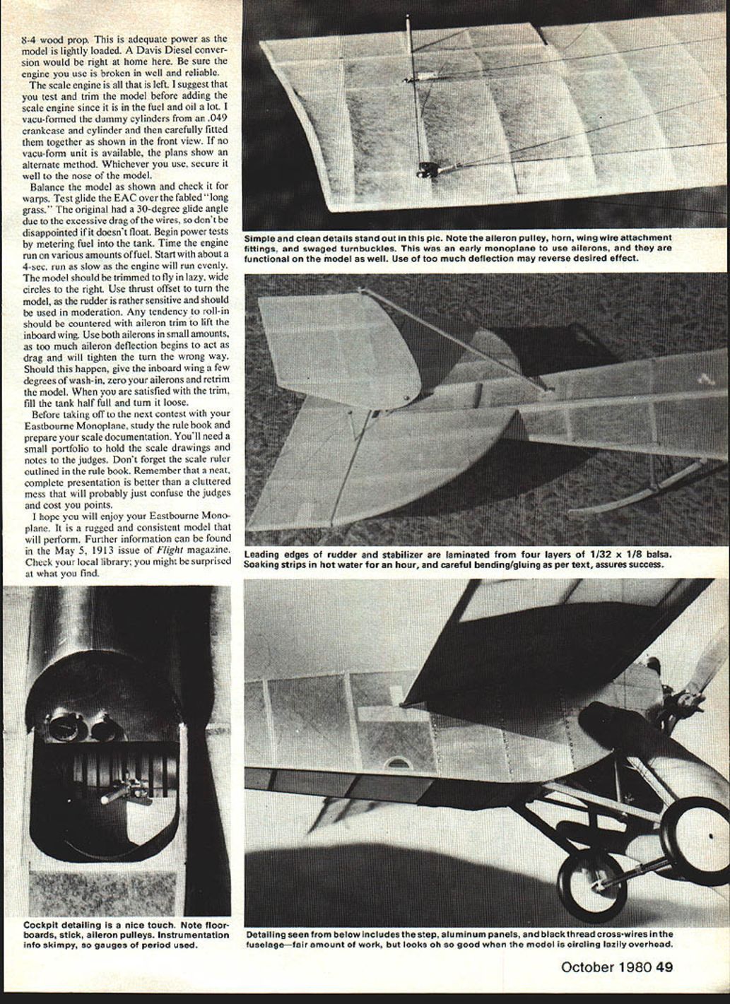
Unlike some contemporary monoplanes, the EAC used "ailerons," those newfangled surfaces that maintained lateral stability. The empennage holds a few surprises: a full flying rudder was used, along with a fully enclosed rudder horn and control cables. A semi-circular stabilizer with a lifting airfoil straddled the fuselage and supported the large "barndoor" elevator.
Power and performance
The Eastbourne Monoplane was powered by a 35 hp Anzani three-cylinder engine and cruised at about 50 mph. Its performance did not fall short of expectations; reports stated the EAC was smooth and pleasant to fly. Alas, the EAC fell victim to the call of World War I and slipped into obscurity.
The Model — design approach
The model was built as closely to the original as possible, sharing a few modern ideas while retaining the prototype's strength and simplicity.
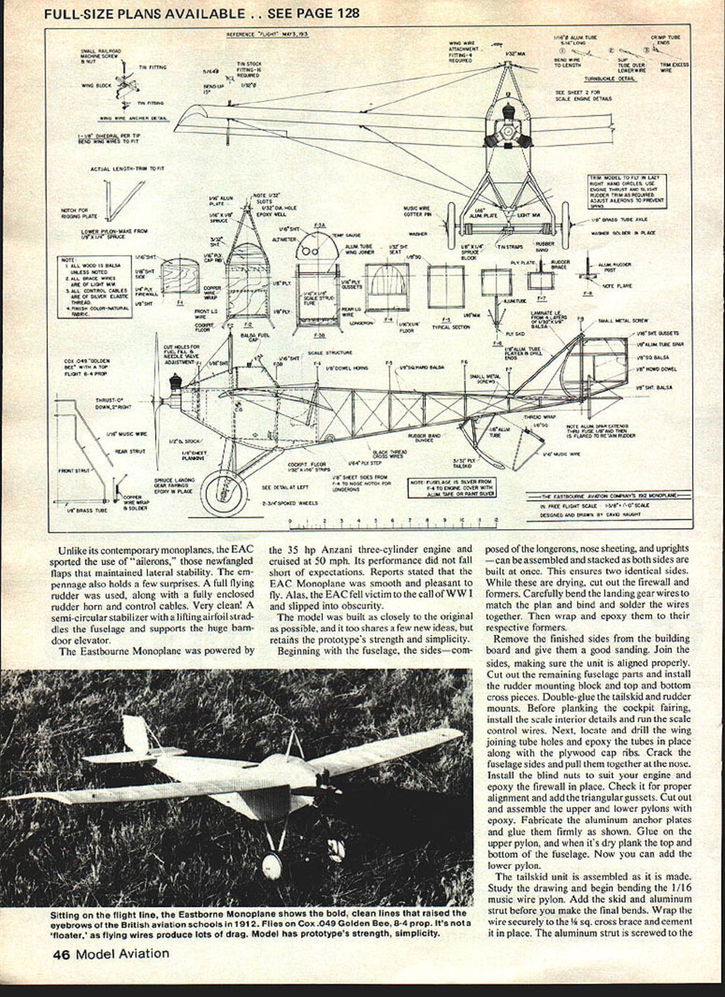
Fuselage construction (recommended sequence)
- Assemble the fuselage sides (longerons, nose sheeting and uprights) stacked together so both sides are built at once; this ensures identical sides.
- While the sides dry, cut out the firewall and formers.
- Bend and assemble landing gear wires to match the plan; bind and solder the joints, then wrap and epoxy them to their respective formers.
- Remove the finished sides from the building board, sand them, and join them, ensuring proper alignment.
- Cut remaining fuselage parts and install the rudder mounting block and top and bottom cross pieces.
- Double-glue the tailskid and rudder mounts.
- Before planking the cockpit fairing, install scale interior details and run the scale control wires.
- Locate and drill the wing-joining tube holes; epoxy tubes in place along with the plywood cap ribs.
- Crack the fuselage sides and pull them together at the tail; install blind nuts for your engine and epoxy the firewall in place. Check alignment and add triangular gussets.
- Cut out and assemble the upper and lower pylons with epoxy. Fabricate aluminum anchor plates and glue them firmly in position. Glue on the upper pylon; when dry, plank the top and bottom of the fuselage, then add the lower pylon.
Landing gear
- Assemble the tailskid unit following the drawing. Begin bending the 1/16" music-wire pylon; add the skid and aluminum strut before the final bends.
- Wrap the pylon wire securely to the 1/8" square cross brace and cement it in place. Screw the aluminum strut to the fuselage.
- Make all landing-gear fittings as shown in the front view. Slip the brass-tube axle into place and secure it in the center with a brass strip soldered to the lower spreader tube.
- Wrap elastic bands at the axle ends for a working shock system to help absorb hard landings.
- Locate a pair of spoked vintage wheels and mount them on the axle with light wire cotter pins.
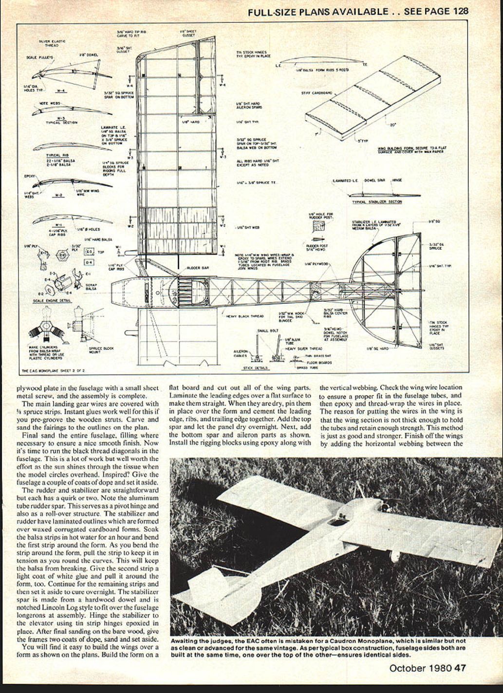
Wing construction
- Place a flat board and cut out all wing parts.
- Laminate the leading edges over a flat surface to make them straight. When dry, pin them in place over the form and cement the leading edge, ribs and trailing edge together.
- Add the top spar and let the panel dry overnight. Next day add the bottom spar and aileron parts.
- Add root ribs and cap ribs; do final sanding and apply two coats of dope.
- Install rigging blocks with epoxy along with vertical webbing.
- Check wing-wire locations to ensure a proper fit with the fuselage tubes, then epoxy and thread-wrap the wires in place. Because the wing section is not thick enough to hold the tubes and retain strength, the wires are fitted in the wing and tied into the fuselage tubes — this method is stronger.
- Finish wings by adding horizontal webbing between ribs and paint.
Notes on ailerons and control runs:
- Make the aileron horns and install them at the angle shown in the side view. Control cables can be simulated with elastic thread.
- Four pulleys can be fashioned from small grommets and cemented in place; run the cables into the root rib and wrap them back under the root rib to the other end of the control horn so tension stays even when settings change.
Rigging and fittings
- Snip out 16 tin strips for the wing-wire fittings and punch the holes as shown. Small fine bolts (model railroad type, 5/8" long) work well to fasten fittings through the wing.
- Bend wire pylon fittings and make the flying wires from .007 music wire. Make top (flying) wires first; they help hold dihedral and, with the lower wires, prevent wing warping. Be careful not to pull in any warps as you fit the wires.
- Fasten the wire ends with the fake turnbuckles illustrated on the plan.
Covering and finish
- The original model was covered with lightweight silkspan; the prototype was linen-covered. To simulate linen, tint clear dope with transparent brown fiberglass dye and apply four or five coats for a slight tan common to aircraft of the era.
- Alternatively, the author suggests covering the model with wet tissue:
- Begin with the fuselage and tail feathers to get into the groove.
- Cut tissue for the wing panels and cover the bottom first. Ensure tissue is well stuck to ribs before covering the top.
- Reshrink tissue on the wings; when dry, give components four or five coats of dope.
- Pin wing panels to a flat surface between coats; after the final coat, pin down panels for about a week to cure.
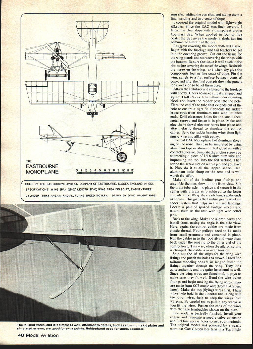
- The real EAC had aluminum sheeting on the nose. Simulate this with aluminum tape or foil glued with contact adhesive. Simulate anchor screws by sharpening a piece of 1/16" aluminum tube to impress a hole, then scribe a screw slot with a pin. Repeat at lapped seams for authenticity.
Tailskid, rudder and elevator assembly
- Attach stabilizer and elevator to the fuselage with epoxy; ensure alignment and squareness.
- Drill a 1/4" hole in the rudder mounting block and insert the rudder post. Flare the end of the tube that extends out of the hole for a tight fit.
- Fabricate rudder brace strut from aluminum tube with flattened ends; drill clearance holes for small sheet-metal screws and fasten in place.
- Make and glue 1/8" dowel elevator horns and attach elastic thread to simulate control cables.
- Bend rudder-bracing wires from light music wire and affix with epoxy.
Engine, scale detail and installation
- The original model used a nearly worn-out Cox Golden Bee turning a Top Flight prop; this proved adequate because the model is lightly loaded. A Davis Diesel conversion would also be suitable.
- Ensure the engine is well broken-in and reliable before flying.
- The scale dummy engine can be vacuum-formed from an .049 crankcase and cylinder, or built using the alternate method shown on the plans if no vacu-form unit is available. Secure the dummy engine well to the nose.
- Install the engine and fabricate needle-valve extension and fuel-line access holes to suit your method.
Trimming and flight testing
- Balance the model as shown on the plans and check for warps.
- Test-glide the EAC gently over long grass. The original had a steep glide (about 30°) due to wire drag, so don't expect a long float.
- Begin power tests by metering fuel into the tank. Time engine runs on various fuel amounts:
- Start with about a 4-second run at the slowest even idle.
- Trim the model to fly in lazy, wide circles to the right.
- Use thrust offset to correct yaw; the rudder is sensitive and should be used sparingly.
- Counter any tendency to roll in with aileron trim to lift the inboard wing; use both ailerons in small amounts. Too much aileron deflection increases drag and tightens the turn the wrong way. If that happens:
- Give the inboard wing a few degrees of wash-in,
- Zero the ailerons and retrim the model.
- When satisfied with trim, fill the tank half full and proceed to full-power tests and normal flying.
Final notes and contest preparation
- Before taking the Eastbourne Monoplane to a contest, study the rule book and prepare scale documentation. Bring a small portfolio with scale drawings and notes for the judges. Include the scale ruler outlined in the rule book.
- A neat, complete presentation is better than a cluttered mess that may confuse judges and cost points.
I hope you will enjoy your Eastbourne Monoplane. It is a rugged, consistent model that will perform. Further information can be found in the May 5, 1913 issue of Flight magazine. Check your local library; you might be surprised at what you find.
Transcribed from original scans by AI. Minor OCR errors may remain.

