
Efficient Speed Control for Electric Power
By Joe Utasi
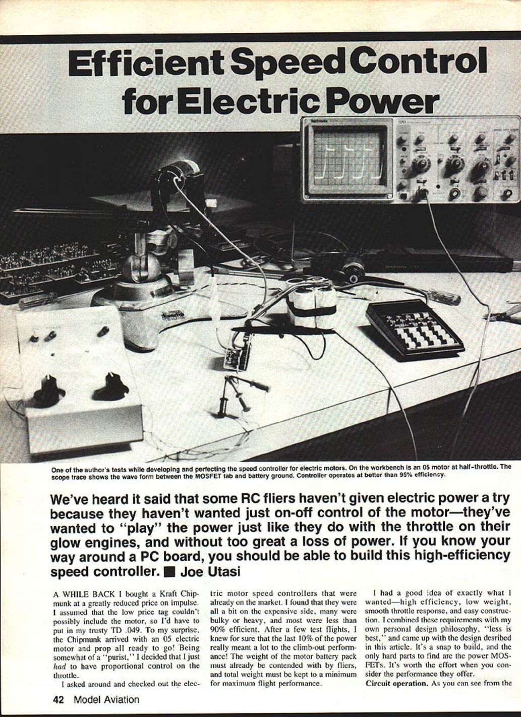
I've heard that some RC fliers avoid electric power because they don't want just on-off control of the motor — they want to "play" the power like a throttle on a glow engine, and without too great a loss of power. If you can work with a PC board, you should be able to build this high-efficiency speed controller.
A while back I bought a Kraft Chipmunk at a greatly reduced price on impulse. I assumed the low price tag couldn't possibly include the motor, so I planned to install my trusty TD .049. To my surprise, the Chipmunk arrived with a .05 electric motor and prop all ready to go! Being somewhat of a purist, I decided I had to have proportional control on the throttle.
I checked the electric motor speed controllers on the market and found most were expensive, bulky or heavy, and often less than 90% efficient. After a few test flights I knew the last 10% of power really mattered to climb-out performance. Weight of the motor-battery pack is already a big concern, so total weight must be minimized for best flight performance.
I wanted high efficiency, low weight, smooth throttle response, and easy construction. Following my design philosophy "less is best," I came up with the design described here. It's easy to build; the hardest parts to find are the power MOSFETs. The performance is worth the effort.
Circuit operation
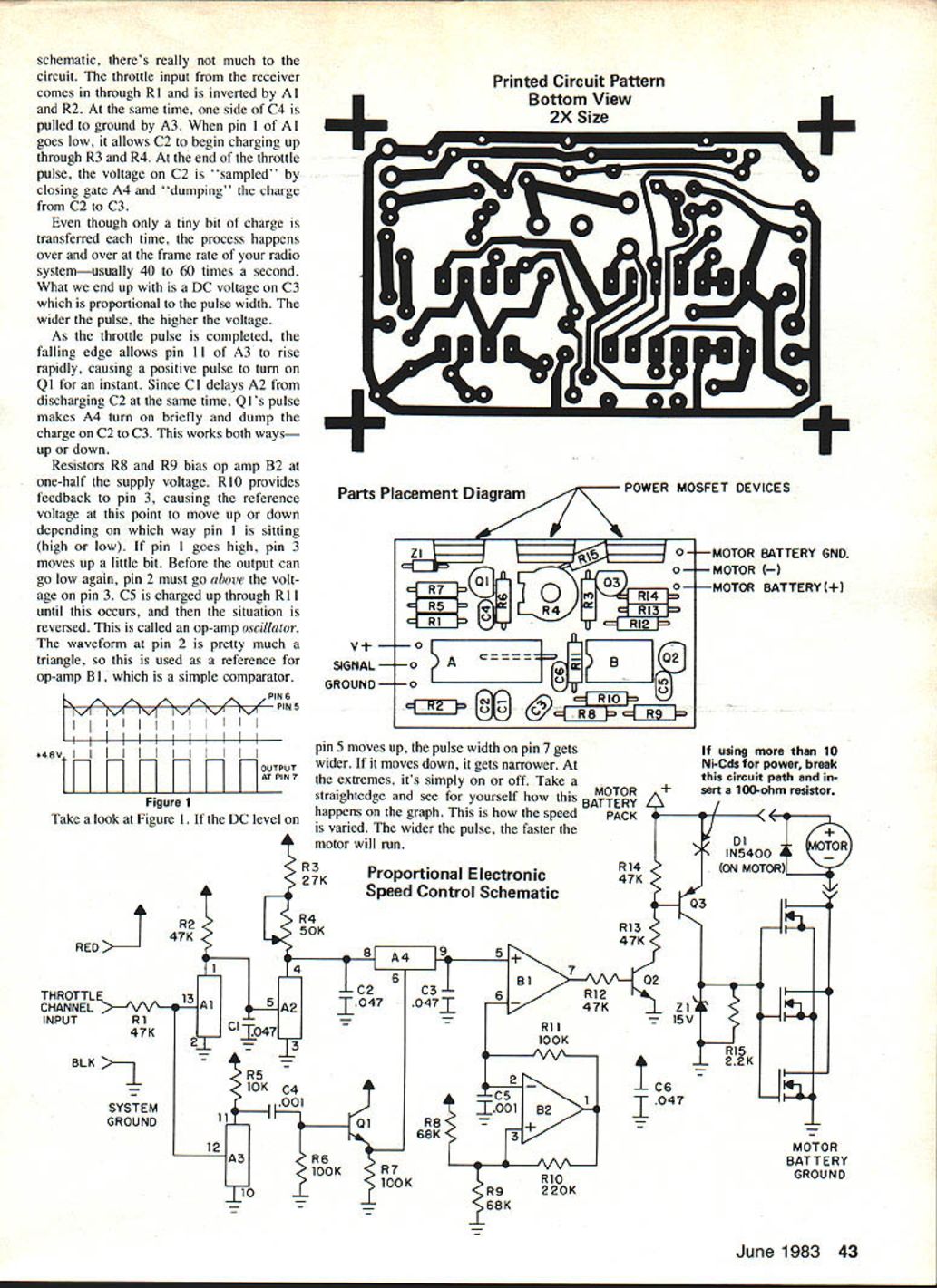
The circuit is simple. The throttle input from the receiver comes in through R1 and is inverted by A1 and R2. At the same time, one side of C4 is pulled to ground by A3. When pin 1 of A1 goes low, C2 begins charging through R3 and R4. At the end of the throttle pulse, the voltage on C2 is sampled by closing gate A4 and dumping the charge from C2 to C3.
Only a small amount of charge transfers each time, but this repeats at the radio frame rate (usually 40–60 times per second). The result is a DC voltage on C3 proportional to the pulse width — the wider the pulse, the higher the voltage.
As the throttle pulse ends, the falling edge allows pin 11 of A3 to rise rapidly, producing a positive pulse that turns on Q1 briefly. Because C1 delays A2 from discharging C2 at the same time, Q1's pulse makes A4 turn on and dump the charge on C2 to C3. This works for both increasing and decreasing throttle.
Resistors R8 and R9 bias op amp B2 at one-half the supply voltage. R10 provides feedback to pin 3, causing the reference voltage at that point to move up or down depending on pin 1's state. If pin 1 goes high, pin 3 moves up slightly; before the output can go low again, pin 2 must go above the voltage on pin 3. C5 charges through R11 until this occurs, then the situation reverses. This creates an op-amp oscillator. The waveform at pin 2 is approximately a triangle, used as a reference for op-amp B1, which is a comparator.
If the DC level on pin 5 moves up, the pulse width on pin 7 gets wider; if it moves down, the pulse narrows. At the extremes it is simply on or off. The wider the pulse, the faster the motor runs.
The oscillator runs around 8–9 kHz, which is suitable. Since this pushes the op amp near its performance limit, Q2 sharpens the pulse edges before feeding Q3. Q3 isolates the motor supply from the speed-control supply and allows maximum voltage drive so the power MOSFETs remain fully turned on. Z1 protects the MOSFETs against voltage transients.
MOSFET selection and protection
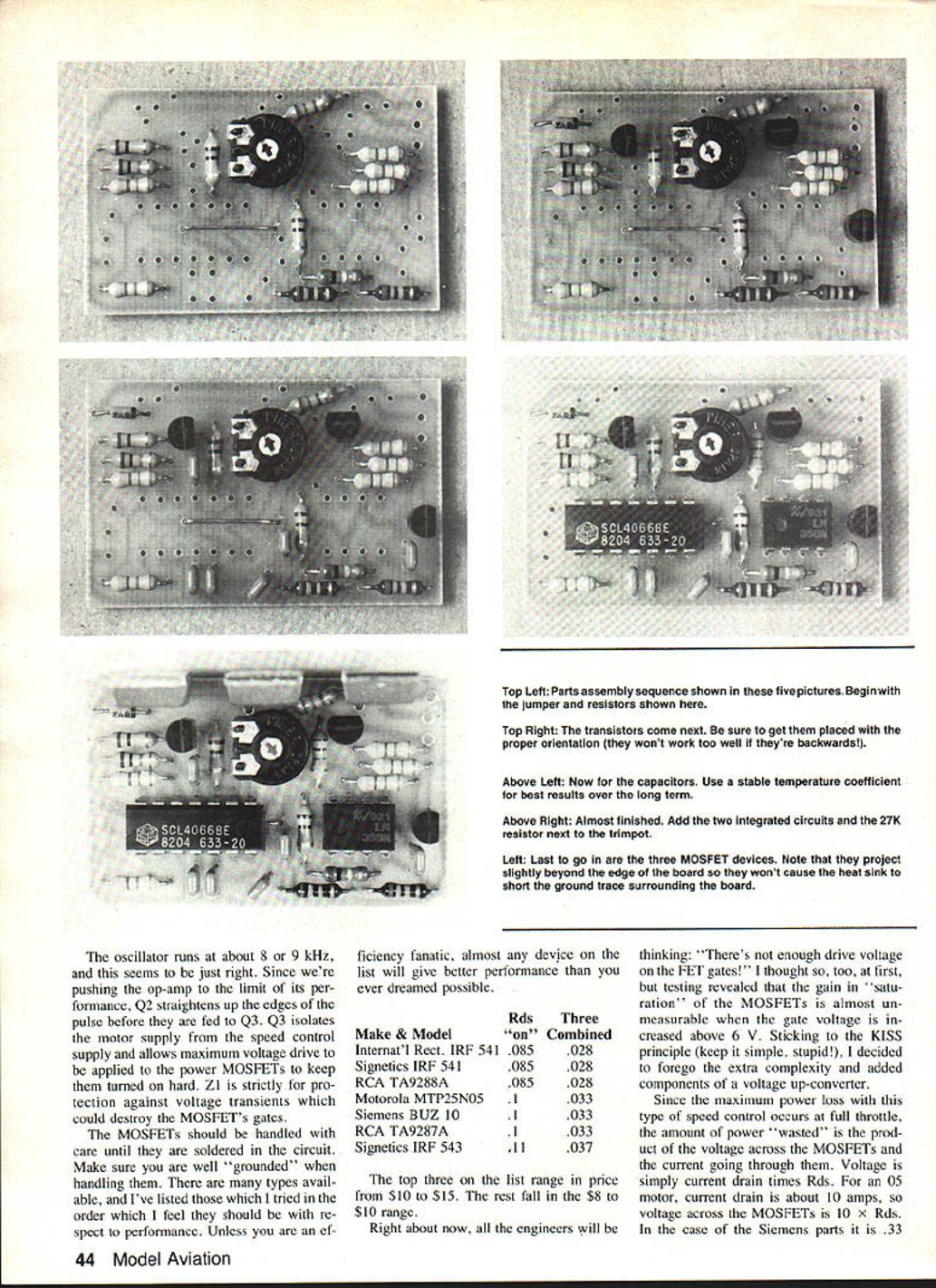
Handle the MOSFETs carefully until they are soldered in place — make sure you are well grounded when handling them. Many MOSFET types will work; those tried here are listed below in order of preferred performance. Unless you are an efficiency fanatic, almost any device on the list will give much better performance than you might expect.
- Make & Model — Rds(on) — Three-on combined
- International Rectifier IRF541 — 0.085 Ω — 0.028 Ω
- Signetics IRF541 — 0.085 Ω — 0.028 Ω
- RCA TA9288A — 0.085 Ω — 0.028 Ω
- Motorola MTP25N05 — 0.085 Ω — 0.033 Ω
- Siemens BUZ10 — 0.10 Ω — 0.033 Ω
- RCA TA9287A — 0.11 Ω — 0.033 Ω
- Signetics IRF543 — 0.11 Ω — 0.037 Ω
The top three range in price from $10 to $15; the others fall in the $8 to $10 range.
You may wonder if there is enough gate drive voltage. Tests showed that MOSFET saturation gain is almost unmeasurable above about 6 V gate drive, so the design avoids adding an up-converter for higher gate voltage to keep things simple.
Maximum power loss occurs at full throttle. Power wasted equals voltage across the MOSFETs times current. Voltage across the MOSFETs is current times Rds. For a .05 motor with about 10 A drain, voltage across the MOSFETs is 10 × Rds. Using the Siemens parts (three in parallel combined Rds ≈ 0.033 Ω), the voltage drop is 0.33 V. For a fully charged six-cell pack (6 × 1.4 = 8.4 V) this is only about a 4% power loss.
When throttle is not wide open and the motor receives pulsed voltage, motor current lags the voltage and builds slowly in the winding. If current is less than maximum, losses across the MOSFETs are even smaller and efficiency improves. At half throttle you can get significantly longer flight time.
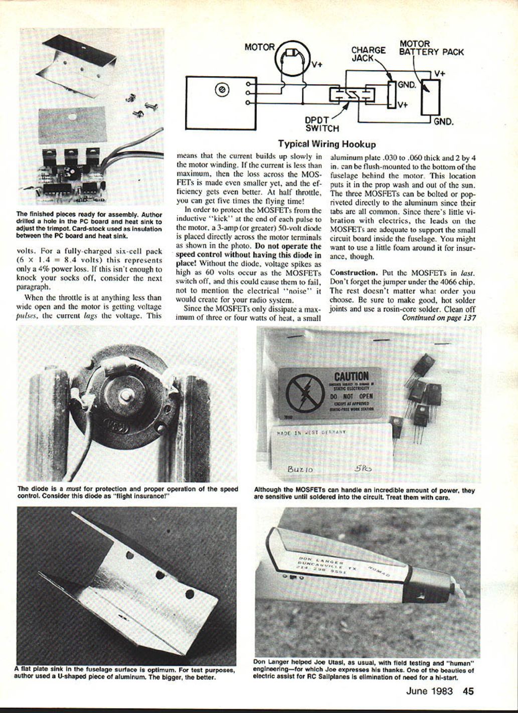
To protect the MOSFETs from inductive kick when switching the motor off, place a 3 A (or greater), 50 V diode directly across the motor terminals. Do not operate the controller without this diode. Without it, voltage spikes as high as 60 V can occur and may destroy MOSFETs and create electrical noise for your radio.
Because MOSFETs dissipate a maximum of only a few watts, a small aluminum plate (0.030" to 0.060" thick, about 2 × 4 in.) can be flush-mounted to the bottom of the fuselage behind the motor. This puts it in the prop wash and out of the sun. The three MOSFETs can be bolted or pop-riveted directly to the aluminum since their tabs are common. The MOSFET leads are usually adequate to support the small circuit board inside the fuselage, though a bit of foam around it is a good precaution.
Construction
- Install the MOSFETs last.
- Do not forget the jumper under the 4066 chip.
- The order of assembling the other components is not critical.
- Make good, hot solder joints with rosin-core solder.
- Clean the board with acetone or lacquer thinner after soldering.
- Clean the heat sink and the motor diode as well.
Adjustment
- Wire the unit as shown and charge your batteries.
- Securely fasten the motor.
- Turn on the transmitter and motor power.
- Adjust trimpot R4 so that with the transmitter stick and trim at full high, the speed just stops increasing.
- When the control is pulsing you will hear a high-pitched whistle. Increase R4 until the whistle just stops — this is the proper setting.
- Throttle back; the motor should slow. Pull the stick and trim all the way back; the motor should stop.
- If it does not stop, your radio's pulse-width variation may be less than 0.8 ms from stop to stop. Change R10 to 240K or 270K to compensate.
Be sure the controller is screwed to a heat sink before use. Even though it is very efficient, it still needs means to dissipate some heat.
Comments
- The speed control is self-protecting: as the motor battery runs down, the MOSFET drive decreases. As the Ni-Cd cells reach discharged state, the MOSFETs will not turn on, helping to protect the batteries.
- When the throttle stick is back and the motor is off, reverse voltage generated by the free-wheeling prop will not be applied to the Ni-Cds.
- Z1 on the board provides protection against voltage transients that could destroy the MOSFETs.
- Note: the project is slightly beyond the edge of the board and will not cause a heat-sink short. A ground trace surrounds the board.
Parts List
Resistors
- R1, R2, R12, R13, R14 — 47K
- R3 — 27K
- R4 — 50K Piher trimpot
- R5 — 10K
- R6, R7, R11 — 100K
- R8, R9 — 220K
- R15 — 2.2K
Capacitors
- C1, C2, C3, C6 — AVX 0.047 µF, 50 V, CK7 tempco
- C4, C5 — AVX 0.001 µF, 50 V
Transistors
- Q1, Q2 — 2N3904
- Q3 — 2N3906
Integrated Circuits
- A1–A4 — CD4066
- B1, B2 — LM358
MOSFETs
- Siemens BUZ10 or equivalent (60 V, 20 A, Rds(on) ≈ 0.1 Ω) — three in parallel recommended
- Other acceptable models: IRF541, TA9288A, MTP25N05, TA9287A, IRF543 (see list above)
Miscellaneous
- PC board, wire, solder, heat sink
- 3 A (or greater), 50 V diode across motor terminals
Availability and Pricing
- A finished speed control, including MOSFETs: $49
- Assembled board (less MOSFETs): $29
- Bare printed circuit board, etched, drilled, and solder reflowed: $7.50
- Contact: Jomar Products, 2028 Knightsbridge Dr., Cincinnati, OH 45244.
Transcribed from original scans by AI. Minor OCR errors may remain.

