
Electric
"As a past AMA National Champion, our author has given many designs to those of us in the modeling fraternity. We are both proud and pleased to present this model for electric R/C from his legendary drawing board." — Woody Blanchard
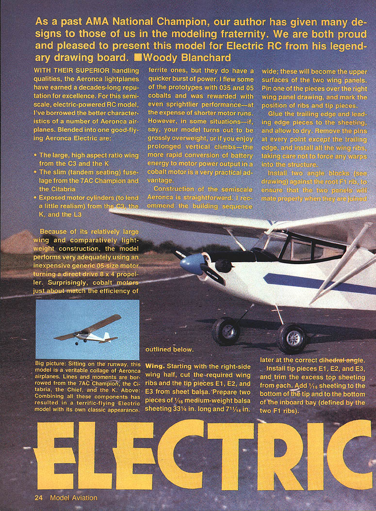
With their superior handling qualities, the Aeronca lightplanes have earned a decades-long reputation for excellence. For this semi-scale, electric-powered R/C model, I've borrowed the better characteristics of a number of Aeronca airplanes. Blended into one good-flying Aeronca Electric are:
- The large, high aspect-ratio wing from the C3 and the K
- The slim (tandem seating) fuselage from the 7AC Champion and the Citabria
- Exposed motor cylinders (to lend a little realism) from the C3, the K, and the L3
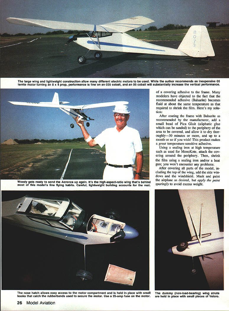
Because of its relatively large wing and comparatively lightweight construction, the model performs very adequately using an inexpensive generic .05-size motor turning a direct-drive 8 x 4 propeller. Surprisingly, cobalt motors just about match the efficiency of ferrite ones, but they do have a quicker burst of power. I flew some of the prototypes with .035 and .05 cobalt motors and was rewarded with even sprightlier performance—at the expense of shorter motor runs. However, in some situations—if, say, your model turns out grossly overweight, or if you enjoy prolonged vertical climbs—the more rapid conversion of battery energy to motor power output in a cobalt motor is a very practical advantage.
Construction of the semi-scale Aeronca is straightforward. I recommend the building sequence outlined below.
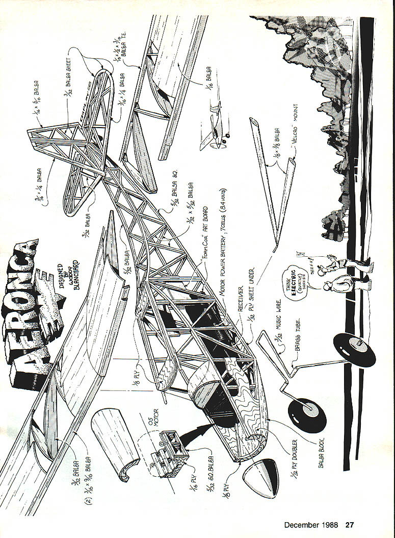
Wing
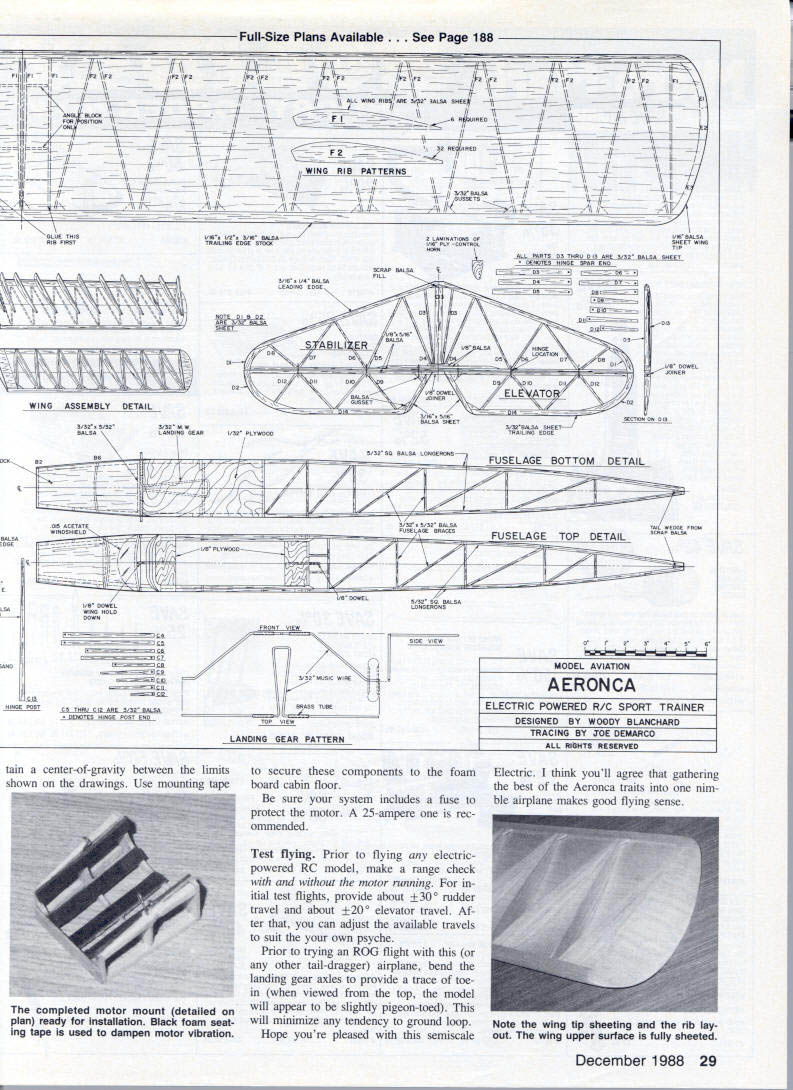
Starting with the right-side wing half, cut the required wing ribs and the tip pieces E1, E2, and E3 from sheet balsa. Prepare two pieces of 1/16" medium-weight balsa sheeting 33 1/4 in. long and 7 1/4 in. wide; these will become the upper surfaces of the two wing panels. Pin one of the pieces over the right wing panel drawing, and mark the position of ribs and tip pieces.
Glue the trailing-edge and leading-edge pieces to the sheeting and allow to dry. Remove the pins at every point except the trailing edge, and install all the wing ribs, taking care not to force any warps into the structure.
Install two angle blocks (see drawings) against the root F1 rib to ensure that the two panels will mate properly when they are joined later at the correct dihedral angle.
Install tip pieces E1, E2, and E3, and trim the excess top sheeting from each. Add 1/16" sheeting to the bottom of the tip and to the bottom of the inboard bay (defined by the two F1 ribs).
Build the left wing in the same manner. (Remember that you want both a right and a left wing panel — and make sure you don't inadvertently build either two rights or two lefts!)
Join the two wing panels as follows: with one wing panel pinned flush to a flat work surface, glue the other panel to it with its tip raised 5 1/2 in. above the work surface. When this is dry, carefully sand the wing. Wrap a 1 x 17-in. piece of glass cloth around the joint formed by the two panels, and attach with either cyanoacrylate (CyA) or epoxy.
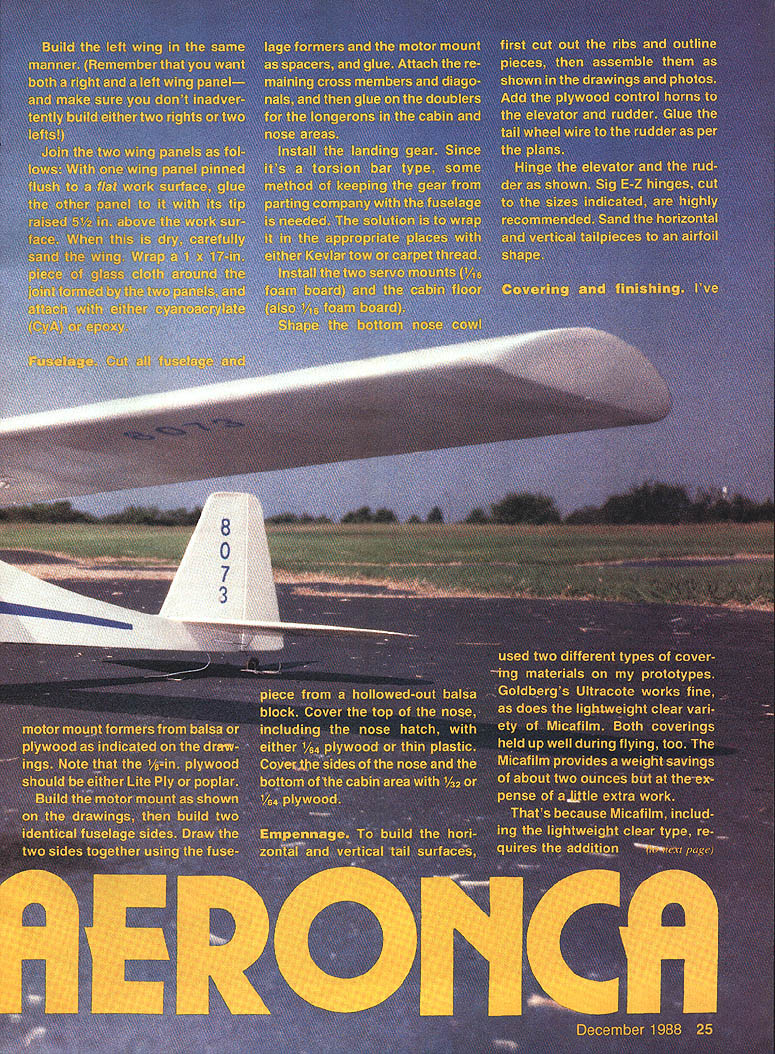
Fuselage
Cut all fuselage and motor mount formers from balsa or plywood as indicated on the drawings. Note that the 1/2-in. plywood should be either Lite Ply or poplar.
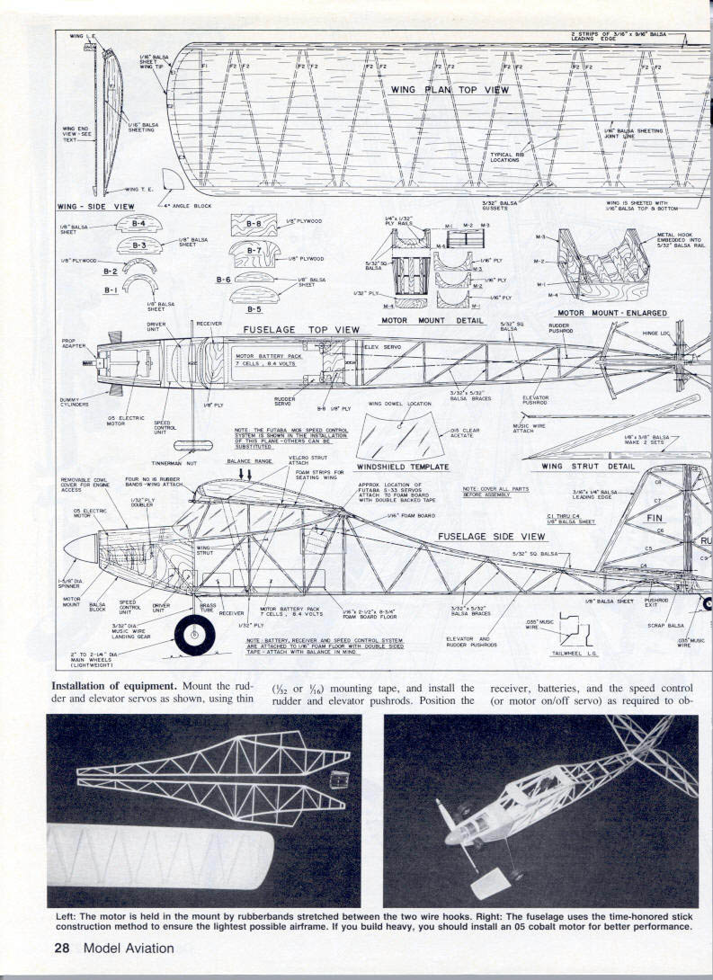
Build the motor mount as shown on the drawings, then build two identical fuselage sides. Draw the two sides together using the fuselage formers and the motor mount as spacers, and glue. Attach the remaining cross members and diagonals, and then glue on the doublers for the longerons in the cabin and nose areas.
Install the landing gear. Since it's a torsion-bar type, some method of keeping the gear from parting company with the fuselage is needed. The solution is to wrap it in the appropriate places with either Kevlar tow or carpet thread.
Install the two servo mounts (1/2" foam board) and the cabin floor (1/8" foam board). Shape the bottom nose cowl piece from a hollowed-out balsa block. Cover the top of the nose, including the nose hatch, with either 1/8" plywood or thin plastic. Cover the sides of the nose and the bottom of the cabin area with 1/32" or 1/64" plywood.
The right fuselage uses the time-honored stick-construction method to ensure the lightest possible airframe. If you build heavy, you should install a .05 cobalt motor for better performance.
Empennage
To build the horizontal and vertical tail surfaces, first cut out the ribs and outline pieces, then assemble them as shown in the drawings and photos. Add the plywood control horns to the elevator and rudder. Glue the tail-wheel wire to the rudder as per the plans.
Hinge the elevator and the rudder as shown. Sig E-Z hinges, cut to the sizes indicated, are highly recommended. Sand the horizontal and vertical tailpieces to an airfoil shape.
Covering and finishing
I've used two different types of covering materials on my prototypes. Goldberg Ultracote works fine, as does the lightweight clear variety of Micafilm. Both coverings held up well during flying, too. Micafilm provides a weight savings of about two ounces but requires a little extra work because it needs a covering adhesive applied to the frame.
Many modelers have objected to the fact that the recommended adhesive (Balsarite) becomes fluid at about the same temperature as that required to shrink the film. Here's my solution:
After coating the frame with Balsarite as recommended by the manufacturer, add a small bead of Pica Glu-It (an aliphatic glue which can be sanded) to the periphery of the area to be covered, and allow it to dry thoroughly — 30 minutes or more, and up to a month if you wish. This product makes a great temperature-resistant adhesive.
Using a sealing iron at the high temperature used for MonoKote, attach the covering around the periphery. Then shrink the film using a sealing iron and/or a heat gun; you won't encounter any problems.
After covering all parts of the model, including the top of the wing, add the side windows and the windshield. Mask and paint the airplane as desired, but apply the paint sparingly to avoid excess weight.
Installation equipment
Mount the rudder and elevator servos as shown, using thin 3/32" or 1/16" mounting tape. Install the receiver, batteries, speed control (or motor on/off servo), and the rudder and elevator pushrods. Position the receiver, batteries, and speed-control unit (or motor on/off servo) as required to obtain proper balance. Use mounting tape to secure these components to the foam-board cabin floor.
Mount the motor on the motor mount as shown. The motor is held in the mount by rubber bands stretched between two wire hooks. Be sure your system includes a fuse to protect the motor — a 25-ampere fuse is recommended.
Prioritize balance and light construction; secure wiring and components so nothing shifts in flight.
Test flying
Prior to flying any electric-powered R/C model, make a range check with and without the motor running. For initial test flights, provide about ±30° rudder travel and about ±20° elevator travel. After that, you can adjust the available throws to suit your own preference.
Prior to trying a rise-off-ground (ROG) flight with this (or any other taildragger) airplane, bend the landing-gear axles to provide a trace of toe-in (when viewed from the top, the model will appear to be slightly pigeon-toed). This will minimize any tendency to ground-loop.
Hope you're pleased with this semi-scale Electric. I think you'll agree that gathering the best of the Aeronca traits into one nimble airplane makes good flying sense.
Transcribed from original scans by AI. Minor OCR errors may remain.

