
Electric Conversion
If you've had a yen to convert a gas design to electric power but lacked the confidence to attempt it, look no further for answers to your questions. —Bob Kopski
Introduction
One of the questions I'm asked most often, as Model Aviation's "Radio Control Electrics" columnist and an active electric flier, is how to convert gas model designs to electric power. Inquiries cover Old-Timers, classic trainers, contemporary trainers, scale, aerobatic, and everything from small to large. No single answer covers all contingencies, so this article focuses on a broad and practical area of interest: electrifying larger, noncompetition models that have basically trainer-like characteristics and are powered by relatively large systems (bigger than .05).
This guidance applies to many Old-Timers and some contemporary designs with classic looks. Examples include Miss America Old-Timer, Buzzard Bombshell, Kloud King, Coronet 150, and contemporary kits such as the Sig Seniorita and Telemaster 40. Some kits (for example, the Telemaster and the Porterfield) are offered in combo packages with an Astro 25 system, which makes the conversion easier; the Porterfield is intended for electric power from the start.
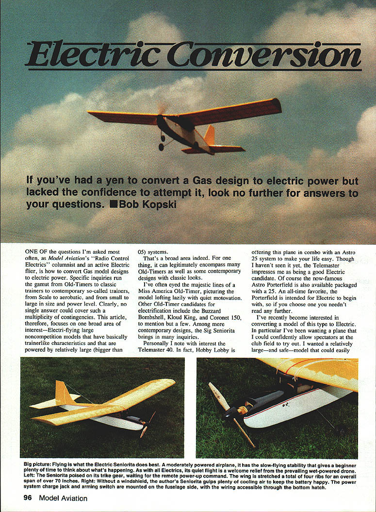
I wanted a plane I could confidently allow spectators at the club field to try. My goals were a relatively large, safe model that handled well on the ground, could be equipped for night flying, could carry a camera for aerial photography, could be fitted with skis for winter use, might tow a small glider, and would provide good duration at cruise power.
The Seniorita kit in stock at a local hobby shop provided the opportunity for this conversion. What follows describes my approach to electrifying the Seniorita; much of this information should apply to other similar models.
Building philosophy
- Build light everywhere, but build strong where needed.
- Light is one thing; fragile is another. Practice thinking "light" before you begin the kit project.
- Use strength selectively (gussets, doublers, formers) at high-load or high-stress points (motor mount, battery compartment, landing loads).
Tail surfaces
I built the tail surfaces first, basically following the kit instructions with a few minor exceptions:
- Substitute unnecessarily heavy kit pieces with wood of the same dimensions.
- Add small gussets and doublers where desirable.
Result: the completed Seniorita tail feathers weighed 14 oz.
Wing modifications
I revised the wing construction in several ways:
- Span extension:
- Some kit wing sticks were longer than required, so I increased each wing panel by two rib bays.
- This lightweight extension added about 120 sq. in. of wing area (approximately 860 sq. in., almost exactly 6 sq. ft.) for only about 2 oz. of extra weight.
- The extension reduced final wing loading by about 15%.
- Spar/web placement:
- I placed shear webs between the top and bottom spars, not on their front edges. It takes slightly more effort but is a better technique for strength.
- Many Old-Timer designs have little or no webbing; use webbing when practical.
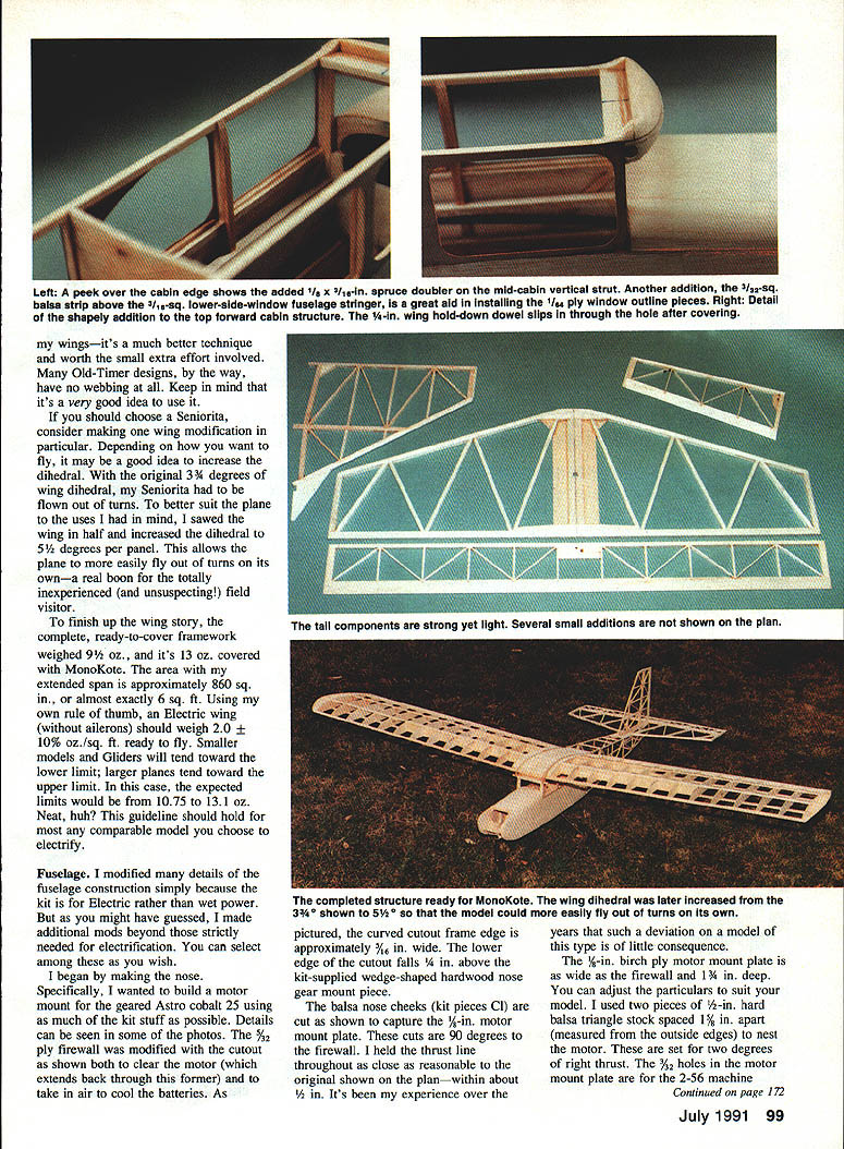
- Dihedral:
- The original Seniorita dihedral was 3-3/4 degrees. I sawed the wing in half and increased dihedral to 5-1/2 degrees per panel.
- The increased dihedral helps the plane fly out of turns on its own—useful when letting inexperienced visitors try the airplane.
- Weights:
- Complete ready-to-cover framework: 9-1/2 oz.
- Covered with MonoKote: 13 oz.
- Rule of thumb: an electric wing (without ailerons) should weigh about 2.0 oz/sq. ft. ±10% ready to fly.
- For a 6 sq. ft. wing, that yields approximately 10.8–13.2 oz. This guideline should hold for comparable models (smaller models and gliders toward the lower limit; larger planes toward the upper limit).
Fuselage modifications
I modified many fuselage details because the kit was intended for glow power rather than electric, and I made additional changes to suit my goals.
- Longerons and structure:
- Built two fuselage sides per kit instructions but substituted 1/16-in. sq. balsa for the original spruce longerons except where extra strength was needed.
- The only 3/16-in. sq. spruce pieces used were the cabin top piece (wing saddle) and the doubler verticals at the leading-edge location.
- The structure aft of the wing trailing edge mainly holds the tail and keeps the pushrods clear of the airflow—no need to overbuild it.
- Additional formers:
- Installed two extra formers to brace and immobilize the relatively heavy battery pack.
- Front former: 1/8-in. balsa sandwiched between two layers of 1/32-in. ply, placed at the leading-edge verticals. It absorbs forces from the battery pack during hard landings.
- Rear former: full-fuselage-depth, cross-grained 1/8-in. balsa glued between the 3/16-in. verticals at the aft edge of the cabin windows; defines the back of the battery compartment.
- Two 1/4-in.-sq. balsa side rails were installed between the formers to locate cells snugly (three popular 1.2-Ah Ni-Cd cells fit between them).
- Notes on design suitability:
- Before electrifying a model, evaluate the fuselage moment (nose length). Models with short nose moments may make it hard to get the final balance right; consider a more forward front former to allow the battery pack to be positioned farther forward to obtain the desired CG.
- If fuselage sides in the cabin area are not parallel (shapely or bowed), use side rails to prevent lateral battery movement.
Nose and motor mount
- Motor choice: geared Astro Cobalt 25 (as an example).
- Fire-wall and nose:
- Modified the 3/32-in. ply firewall with a cutout to clear the motor (which extends back through the former) and to admit cooling air to the batteries.
- Curved cutout frame edge ~3/16 in. wide; lower edge of cutout ~1/4 in. above the kit-supplied wedge-shaped hardwood nose gear mount.
- Motor mount plate:
- 1/8-in. birch ply plate, as wide as the firewall and about 1-3/4 in. deep (adjust to suit your motor/model).
- 3/32-in. holes accept 2-56 machine screws for motor tie-down straps.
- Use two 1/2-in. hard balsa triangle blocks spaced 1/8 in. apart to nest the motor; set for about 2 degrees of right thrust. The nose block assembly also sets some downthrust when glued in.
- Motor tie-down straps were made from the yellow inner of Sullivan Golden Rod pushrods.
- Alternative mounting:
- You can use an Astro radial mount or a Sonic-Tronics mount attached to the stock firewall; if so, plan for an alternate air-intake/cooling scheme.
- Thrust angles:
- Most candidate models benefit from a couple degrees of right thrust and a couple degrees of downthrust.
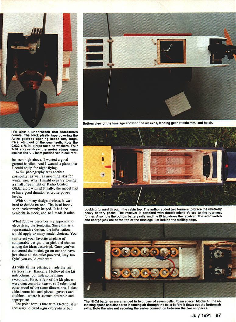
Battery installation and cooling
- Pack arrangement:
- Ni-Cd pack: 14 cells arranged in two rows of seven cells (two subpacks).
- Foam spacer blocks fill remaining space and force incoming air through the cells before it exits the bottom cuts in the fuselage.
- A wire nut secures the series connection between the two subpacks.
- Battery retention:
- The front and rear formers and side rails prevent battery movement. The battery is a concentrated mass—typically 20–40% of the model's weight—and should remain stationary in flight.
- In my Seniorita, the 14-cell pack constituted about 31% of total weight.
- Receiver and controls:
- The receiver is attached with double-sticky Velcro to the rearmost former.
- The radio switch and charge jack are located on the top fuselage just behind the wing trailing edge—places that are strong and needed.
Ground handling and flight characteristics
- The electric Seniorita excels at moderate-power flying and slow-flying stability, giving beginners plenty of time to react.
- Quiet flight is a major advantage over glow power.
- The modified dihedral improves self-correcting out-of-turn behavior—important when letting inexperienced visitors fly the plane.
- The model also makes a good platform for night flying, aerial photography, skis for winter use, and towing small free-flight or R/C gliders.
Practical tips and checklist
- Think light but not fragile: substitute heavy kit parts with lighter materials of the same dimensions, and add gussets/doublers only where needed.
- Evaluate the plan for:
- Adequate nose moment to balance the added weight of batteries (move formers forward if necessary).
- Cabin geometry—install side rails if sides are not parallel to prevent lateral battery shift.
- Provide battery ventilation: force airflow across the cells with inlet and outlet cutouts and foam spacers to channel air.
- Secure batteries: add formers, rails, and locking mechanisms to prevent pack movement on hard landings.
- Motor mount:
- Keep the thrust line close to the original plan (within about 1/8 in. is acceptable for this type of model).
- Include small amounts of right and down thrust.
- Consider factory-mounted radial or alternative mounts for ease of installation, but ensure adequate cooling.
Conclusion
Converting a trainer-like gas model to electric power is practical and highly rewarding. With attention to light-but-strong construction, proper motor mounting, careful battery placement and cooling, and modest wing/fuselage modifications, you can produce a quiet, safe, and forgiving airplane suitable for beginners, spectators, and a variety of recreational uses. Choose a model whose moments and fuselage geometry are amenable to carrying the battery load, then apply these techniques and enjoy the quiet, lazy flying experience electric power delivers.
Transcribed from original scans by AI. Minor OCR errors may remain.

