
Electric Country Boy
Developed by Bill Jenkins & Jim Clem Text and Photos by Larry Kruse
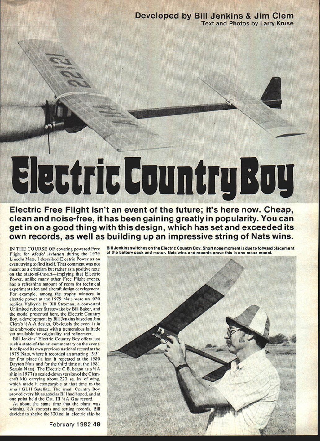
Electric Free Flight isn't an event of the future; it's here now. Cheap, clean and noise-free, it has been gaining greatly in popularity. You can get in on a good thing with this design, which has set and exceeded its own records, as well as building up an impressive string of Nats wins.
In the course of covering powered Free Flight for Model Aviation during the 1979 Lincoln Nats, I described Electric Power as an event trying to find itself. That comment was not meant as a criticism but rather as a positive note on the state of the art—implying that Electric Power, unlike many other Free Flight events, has a refreshing amount of room for technical experimentation and aircraft design development.
For example, among the trophy winners in electric power at the 1979 Nats were an .020 replica Valkyrie by Bill Stroman, a converted Unlimited rubber Stratowake by Bill Baker, and the model presented here, the Electric Country Boy, a development by Bill Jenkins based on Jim Clem's 1/4-A design. Obviously the event is in its embryonic stages with a tremendous latitude yet available for originality and refinement.
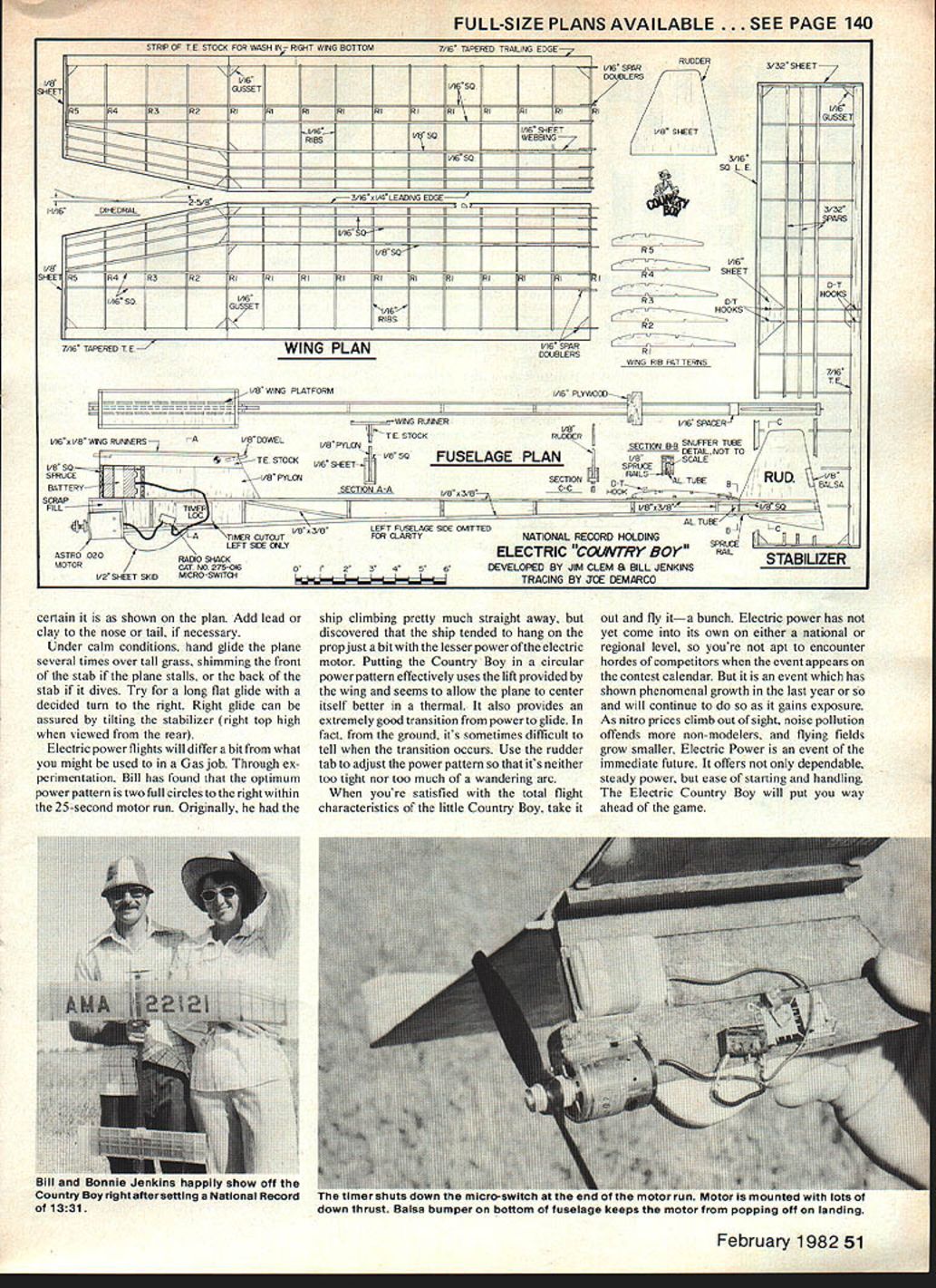
Bill Jenkins' Electric Country Boy offers just such a state-of-the-art commentary on the event. It eclipsed its own previous national record at the 1979 Nats, where it recorded an amazing 13:31 for first place (a feat it repeated at the 1980 Dayton Nats and for the third time at the 1981 Seguin Nats). The Electric C.B. began as a 1/4-A ship in 1977 (a scaled-down version of the Clemcraft kit) carrying about 220 sq. in. of wing, which made it comparable at that time to the small GLH Satellite. The small Country Boy proved every bit as good as Bill had hoped, and at one point held the Cat. III 1/2A Gas record.
At about the same time that the plane was winning 1/2A contests and setting records, Bill decided to shelve the 320 sq. in. electric ship he was building.
Construction
Wood selection is important in building a competition Free Flight model. Use good, light A-grain for fuselage sides, C-grain for wing and stab ribs. Spars and stringers should be light A-grain with good resiliency. Avoid overly heavy, hard, brittle pieces. Particularly avoid wood that appears excessively soft or mushy.
Fuselage employs a basic framework built directly over the plan. Fuselage sides, pylon and rudder longerons are 1/8 x ? (see plan for dimensions) strips; vertical members are 1/8 sq. strips. Rudder area is assembled flat over the plan. I can't emphasize the flat aspect too much — it's the way to assure accuracy and proper alignment.
After the fuselage framework dries, use the pattern to cut out both right and left fuselage sides. Glue sheet sides to both sides of the frame using Titebond or similar glue. Weight the assembly down until it dries. Again, the word flat comes to mind.
You will note no nose block or firewall is employed; the motor is simply epoxied to the fuselage at the angles shown on the plan. Scrap fill pieces can be added to either side of the motor to give additional gluing surface. The on-board battery pack is fitted and epoxied over the hole cut in the pylon after basic assembly. Spruce pieces at the front and back of the pack are used as necessary to wedge the pack firmly in place.
The Radio Shack microswitch has two small mounting holes and can be held in place with toothpick pieces. The fuselage switch must be mounted so the timer arm comes down and the switch lever cuts off current. Keeping fingers from entanglement can best be handled by gathering up slack wires and securing them to the fuselage sides with small U-shaped pins.
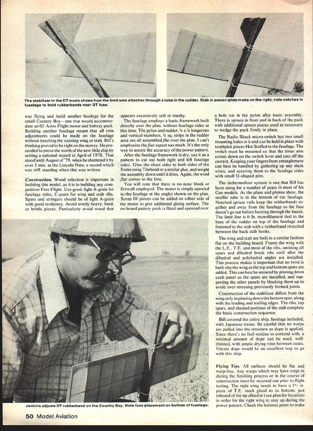
The dethermalizer system Bill has been using for a number of years on his gas models is used here. As the plans and photos show, a snuffer tube runs along the bottom of the fuselage. Notched spruce rails keep the rubber bands together and away from the fuselage so the fuse doesn't go out before burning through the bands. A limit line of 6-lb monofilament is tied to the base of the rudder and the top of the fuselage and fastened to the stab rubber band stretched between the back stab hooks.
Wing and stab are built in similar fashion, flat on the building board. Frame the wing leading and trailing edges and fit ribs, omitting the spars. Do not cut the dihedral break ribs until after dihedral/polyhedral angles are installed; this process makes it important that no twist be built into the wing. When top and bottom spars are added, proper alignment can best be ensured by pinning down the panel spars, installing and supporting other panels, and blocking up to avoid over-flexing the panels.
Construction of the stabilizer differs from the wing only in pinning down the bottom spar, along with the leading and trailing edges. The ribs, top spars and sheeted portions of the stab complete the basic construction sequence.
Bill covered the entire ship, fuselage included, with Japanese tissue. Be careful that no warps are pulled into the structure as dope is applied. Since there's no fuel residue to contend with, a minimal amount of dope can be used, well-thinned, with ample drying time between coats. Nitrate dope would be an excellent way to go with this ship.
- Tips on materials and alignment:
- Use light A-grain for fuselage sides and spars; C-grain for ribs.
- Avoid heavy, brittle, or mushy wood.
- Assemble and glue flat over the plan for best accuracy.
- Refer to the plan for exact strip dimensions.
Flying Tips
All surfaces should be flat and warp-free. Any warps which may have crept in during the finishing process or in the course of construction must be steamed out prior to flight testing.
The right wing needs to have a 1/8 in. piece of T.E. stock glued to its bottom, just inboard of the tip dihedral (see plan for location) in order for the right wing to stay up during the power pattern. Check the balance point to make sure it is at the point shown on the plan. Add lead or clay to the nose or tail, if necessary.
Under calm conditions, hand-glide the plane several times over tall grass, shimming the front of the stab if the plane stalls, or the back of the stab if it dives. Try for a long, flat glide with a decided turn to the right. Right glide can be assured by tilting the stabilizer (right top high when viewed from the rear).
Electric power flights will differ a bit from what you might be used to in a gas job. Through experimentation, Bill has found that the optimum power pattern is two full circles to the right within the 25-second motor run. Originally, he had the ship climbing pretty much straight away, but discovered that the ship tended to hang on the prop just a bit with the lesser power of the electric motor. Putting the Country Boy in a circular power pattern effectively uses the lift provided by the wing and seems to allow the plane to center itself better in a thermal. It also provides an extremely good transition from power to glide. In fact, from the ground, it's sometimes difficult to tell when the transition occurs. Use the rudder tab to adjust the power pattern so that it's neither too tight nor too much of a wandering arc.
When you're satisfied with the total flight characteristics of the little Country Boy, take it out and fly it—a bunch. Electric power has not yet come into its own on either a national or regional level, so you're not apt to encounter hordes of competitors when the event appears on the contest calendar. But it is an event which has shown phenomenal growth in the last year or so and will continue to do so as it gains exposure.
As nitro prices climb out of sight, noise pollution offends more non-modelers, and flying fields grow smaller, Electric Power is an event of the immediate future. It offers not only dependable, steady power, but ease of starting and handling. The Electric Country Boy will put you way ahead of the game.
Transcribed from original scans by AI. Minor OCR errors may remain.

