
Electric Hurricane
Steve Crowe
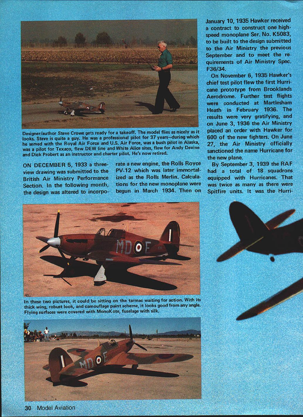
Designer/author Steve Crowe gets ready for a takeoff. The model flies as nicely as it looks.
Steve is quite a guy. He was a professional pilot for 37 years—during which he served with the Royal Air Force and U.S. Air Force, was a bush pilot in Alaska, was a pilot for Texaco, flew DEW Line and White Alice sites, and flew for Andy Devine and Dick Probert as an instructor and charter pilot. He's now retired.
History of the Hawker Hurricane
On December 5, 1933 a three-view drawing was submitted to the British Air Ministry Performance Section. In the following month, the design was altered to incorporate a new engine, the Rolls-Royce PV-12, which was later immortalized as the Rolls-Royce Merlin. Calculations for the new monoplane were begun in March 1934. Then on January 10, 1935, Hawker received a contract to construct one high-speed monoplane Ser. No. K5083, to be built to the design submitted to the Air Ministry the previous September and to meet the requirements of Air Ministry Spec. F36/34.
On November 6, 1935 Hawker's chief test pilot flew the first Hurricane prototype from Brooklands Aerodrome. Further test flights were conducted at Martlesham Heath in February 1936. The results were very gratifying, and on June 3, 1936 the Air Ministry placed an order with Hawker for 600 of the new fighters. On June 27, the Air Ministry officially sanctioned the name Hurricane for the new plane.
By September 3, 1939 the RAF had a total of 18 squadrons equipped with Hurricanes. That was twice as many as there were Spitfire units. It was the Hurricane that carried the load of the first eight months of air fighting in France, and it gave the Luftwaffe its first taste of defeat.
Following the collapse of France, the stage was set for the Battle of Britain, which encompassed operations from July to October 1940. During this time, a total of 1,715 Hurricanes were flown in combat, more than the total of all other aircraft involved in the conflict. The Hurricane claimed 80% of the victories during that fateful summer. On July 1 the RAF had 29 Hurricane units and 19 Spitfire squadrons, while Fighter Command Groups 10, 11, and 12, on July 7, showed 22 Hurricane units and only 13 equipped with Spitfires. Two months later, at the peak of battle, a total of 30 Hurricane units were complemented by 18 Spitfire units and 10 other fighter squadrons.
Statistics illustrate the high debt owed to the Hurricane during that epic battle and defense of England. In my view, the Spirit of Biggin Hill really belongs to the Hurricane, the first RAF fighter to exceed 300 mph in level flight. The Hurricane remained a first-line fighter until the end of hostilities.
Why an Electric Hurricane?
Why does a person choose a particular model to construct? Any number of things can influence this. Maybe it's the eye-pleasing lines or the paint scheme. Maybe the design has just that right look that will make it stand out from the rest and also be a good flier. It could be all of these things, plus a bit of nostalgia from the person being involved with the particular full-size aircraft somewhere in the past. My particular attachment to this wonderful old bird comes from having sat in the cockpit of one and gunning it through the skies over England in 1941 and 1942.
Designing and building this Hurricane was a real pleasure. I've always wanted to have a Hurricane in my stable of models, but I kept procrastinating until I saw Don Srull's Spitfire in the October 1981 Model Aviation. This was the push I needed.
This airplane has nostalgia written all over it. Proportions of the Hawker Hurricane Mk I make it an excellent RC flier, and quiet electric power (geared Astro 15) makes it a joy to be around. It has rudder, elevator, aileron, and motor controls. While not the easiest model in the world to build, the results are well worth the effort.
Power and Equipment
Why Electric? I'd been fooling around with a Kraft Chipmunk, and I was very impressed with the silence and smoothness of control. The more I flew it, the greater the urge became to build something larger and with more power. I was a little reluctant, in the beginning, to tackle such an electric model, but after reading about the success of Srull's Spitfire, I threw caution to the wind and started full-steam.
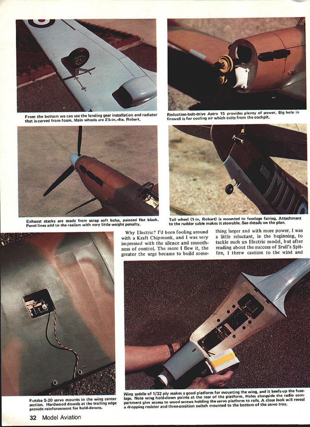
The geared Astro 15 provides plenty of power. The reduction-belt-drive Astro 15 is mounted on a lite-ply firewall doubled to 3/16 in. The cowl is carved foam. Cooling air exits through the cockpit area.
Main wheels are 2-1/4-in. dia., Robart. Futaba S-20 servo mounts are located in the wing center section. Hardwood dowels in the trailing edge provide reinforcement for the wing hold-downs.
Exhaust stacks are made from scrap soft balsa and painted flat black. Panel lines add realism with very little weight penalty.
Tailwheel is a 1-in. Robart mounted in a fuselage fairing. The rudder cable attachment makes it steerable (see details on the plan).
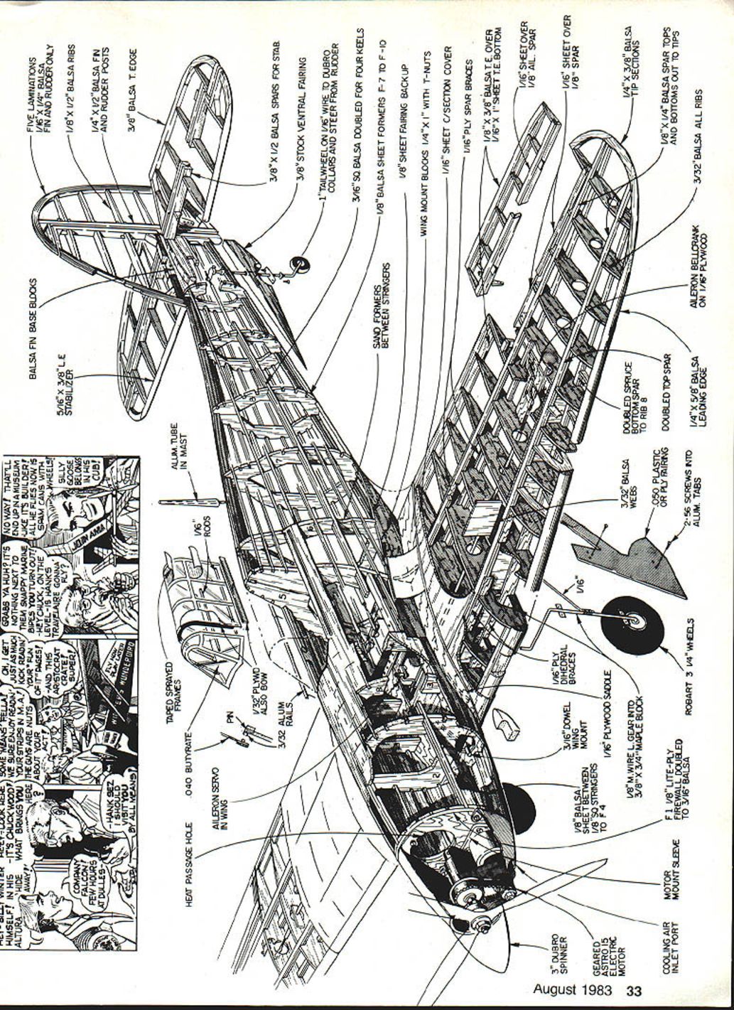
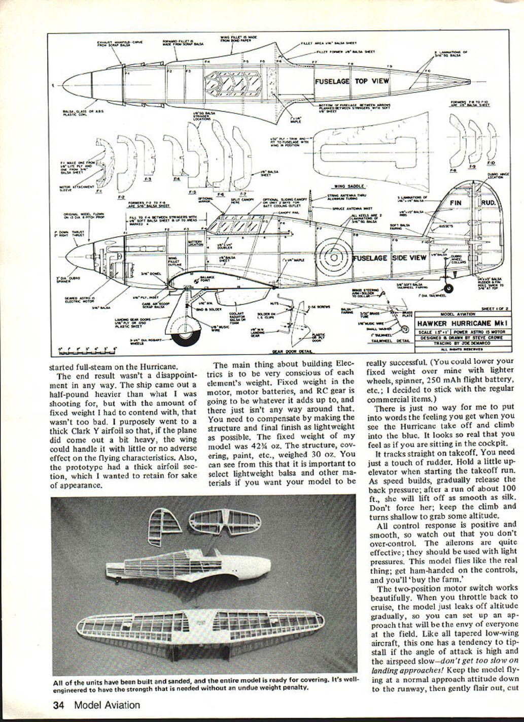
Stabilizer: five laminations of 1/16 x 3/8 balsa. Fin and rudder: 1/8 x 1/2 balsa. Ribs: 1/4 x 1/2 balsa. Leading edges, tip sections, spars, and other structural members are built up from the balsa and ply sizes shown on the plan. Follow the plan for exact lamination and ply doublers for the wing mount blocks, spar construction, and fuselage former positions.
The end result wasn't a disappointment in any way. The ship came out a half-pound heavier than what I was shooting for, but with the amount of fixed weight I had to contend with, that wasn't too bad. I purposely went to a thick Clark Y airfoil so that, if the plane did come out a bit heavy, the wing could handle it with little or no adverse effect on the flying characteristics. Also, the prototype had a thick airfoil section, which I wanted to retain for sake of appearance.
The main thing about building electrics is to be very conscious of each element's weight. Fixed weight in the motor, motor batteries, and RC gear is going to be whatever it adds up to, and there just isn't any way around that. You need to compensate by making the structure and final finish as lightweight as possible. The fixed weight of my model was 42-1/2 oz. The structure, covering, paint, etc., weighed 30 oz. You can see from this that it is important to select lightweight balsa and other materials if you want your model to be really successful. (You could lower your fixed weight below mine with lighter wheels, spinner, a 250 mAh flight battery, etc.; I decided to stick with the regular commercial items.)
There is just no way for me to put into words the feeling you get when you see the Hurricane take off and climb into the blue. It looks so real that you feel as if you are sitting in the cockpit. It tracks straight on takeoff. You need just a touch of rudder. Hold a little up-elevator when starting the takeoff run. As speed builds, gradually release the back pressure; after a run of about 100 ft., she will lift off as smooth as silk. Don't force her; keep the climb and turns shallow to grab some altitude.
All control response is positive and smooth, so watch out that you don't over-control. The ailerons are quite effective; they should be used with light pressures. This model flies like the real thing; get ham‑handed on the controls, and you'll "buy the farm."
The two-position motor switch works beautifully. When you throttle back to cruise, the model just leaks off altitude gradually, so you can set up an approach that will be the envy of everyone at the field. Like all tapered low-wing aircraft, this one has a tendency to tip-stall if the angle of attack is high and the airspeed slow—don't get too slow on landing approaches! Keep the model flying at a normal approach attitude down to the runway, then gently flare out, cut throttle, and she'll settle right down.
This ship also makes beautiful wheel landings, so don't be afraid to grease her in tail‑high.
Recommended control throws
- Rudder: 1/2 in. left and right
- Elevator: 3/4 in. up and down
- Ailerons: 3/8 in. up, 1/2 in. down
- Throttle switch: forward position for high speed
Construction
Fuselage
The fuselage is built-up using the half‑shell method. It is lightweight and very strong when the stringers are added. Start by laying up all the fuselage keels. When completed, lay down the keels on the fuselage side‑view plan, and add the bulkheads at their respective stations.
Make certain that they are all at 90° to the keel. Add the side keel. Make sure that all the bulkheads are square, and glue them in place. You should now have a fuselage half‑shell.
Remove from the plan, and add the bulkheads to the opposite side. Upon completion, start adding the stringers in an alternating pattern; keep sighting down the main keels and correcting as necessary to keep the fuselage true.
You will notice that only a few of the stringer locations are marked on the bulkhead drawings of the plans. Cutting all the stringer notches in the bulkheads in advance isn't recommended, as this is apt to produce wavy stringers. It is better to use the actual stringers as a guide. Here's how: notch a forward bulkhead, lay the stringer in the notch, pin the stringer at its proper location at the tail post, and (using the stringer as a guide) mark all the other bulkhead notches. This method will produce a straight fuselage that will look great when it's covered.
Inlay 1/8-in. soft balsa between stringers on the forward section of the fuselage as called for on the plans.
Wing fillets
I've tried many ways, but the stiff bond paper method is the best. It's lightweight, strong, and very realistic when completed. The method is purely trial-and-error. Cut out a few patterns, and lay them up against the fuselage. Cut a little at a time from the pattern until you obtain the proper fillet contour. Be sure to make up the fillet contour formers, as they will help on final installation. When the fillets are glued in place, give them a few coats of nitrate dope. This will make them tougher and provide a good base on which to paint the final finish.
You won't be able to glue on the wing fillets until the 1/32-in. plywood wing saddle has been installed on the fuselage. Therefore, the next step would be to build the wing assembly.
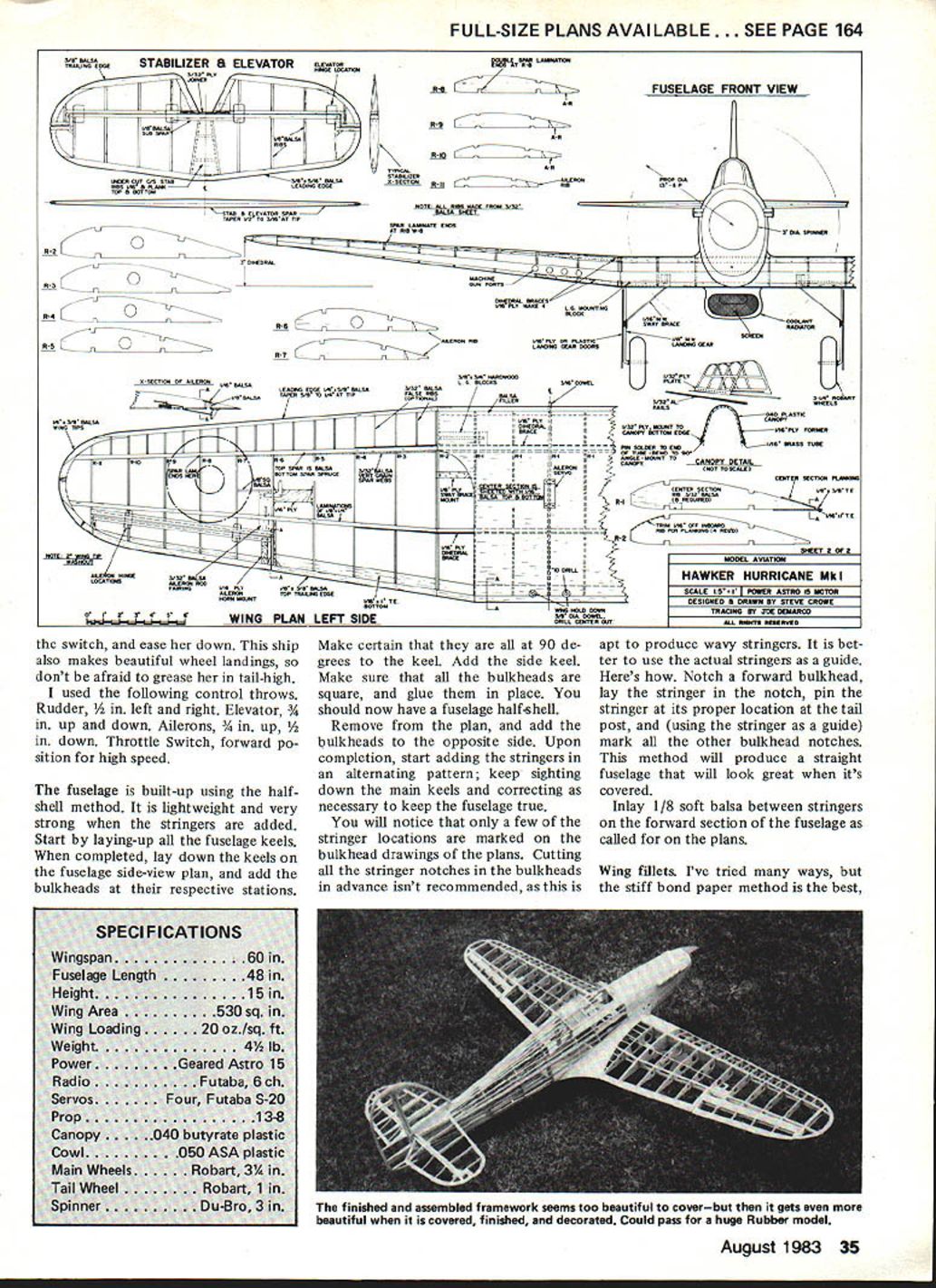
Wing
Start by laminating the wing spars from 1/4 x 1/8 hard balsa and spruce.
Next, cut out the dihedral joiners from 1/16-in. plywood; set aside until all the ribs have been cut from 3/32-in. balsa; make all necessary cutouts in the ribs for gear mounting blocks and lightening (aileron rods go through these holes).
Build the center section first. Lay down the spars, and position the ribs. Cut the spars at the dihedral breaks. After the ribs are glued, add the top spars and the ply dihedral joiners. The joiners will extend beyond the butt ribs approximately 5 in. (don't cut them off, as they will be glued to the spars of the outer panels).
Lay down the spars for the outer panels, and build these units, complete with ailerons. When finished, slide the panels onto the joiners. Note that the spar joiners will have to be bent to fit flush with the faces of the spars due to the taper in the outer panels. Bend them as necessary, add glue, and clamp with clothespins until dry.
Plank the center section with 1/16-in. sheet balsa. Be certain that the dihedral in both panels is equal. Install the aileron rods, bellcranks, and servo.
With the wing built, you can now return to the fuselage. Cut the 1/32-in. ply wing saddle, and fit it into the awaiting cavity. Check the fit of the saddle with the wing in place; shim the ply as necessary to obtain a good fit with the wing. Now, you can go back and complete the wing fillet. Since the fillet tapers rather sharply at the leading edge, build this portion from scrap soft balsa blocks, blending into the fuselage with 180-grit sandpaper wrapped around a 3/8-in. dowel.
Radiator
This appendage fits under the wing center section. It doesn't have any function on the model, but without it the Hurricane would look rather naked. I tried something new for me by making the radiator from 2-lb.-density polyurethane foam. The foam is very easy to carve to shape and sand.
After final sanding, one coat of aliphatic-resin glue, thinned with water, was applied. When dry, it was sanded with 320-grit wet-or-dry paper. A layer of silkspan was applied with a second coat of the glue, followed by a slurry of water-thinned DAP vinyl paste. When this was dry, it was sanded to a smooth finish. All of this sounds heavy, but the final result really is quite light, and the radiator looks great hanging under the wing. Prepared this way, it takes a beautiful finish when painted. You could build the radiator from a balsa block, but I think the foam is better and also quicker.
Tail surfaces
My model, as shown on the plans, was constructed with tapered spars for both the horizontal and vertical tail surfaces. I started to build them flat, but upon completion I found that they just didn't look right. I built another set with the taper. It was a little more work, but I liked the end result. (I'm sure the model would fly okay with a flat stab and rudder if that is the builder's choice.)
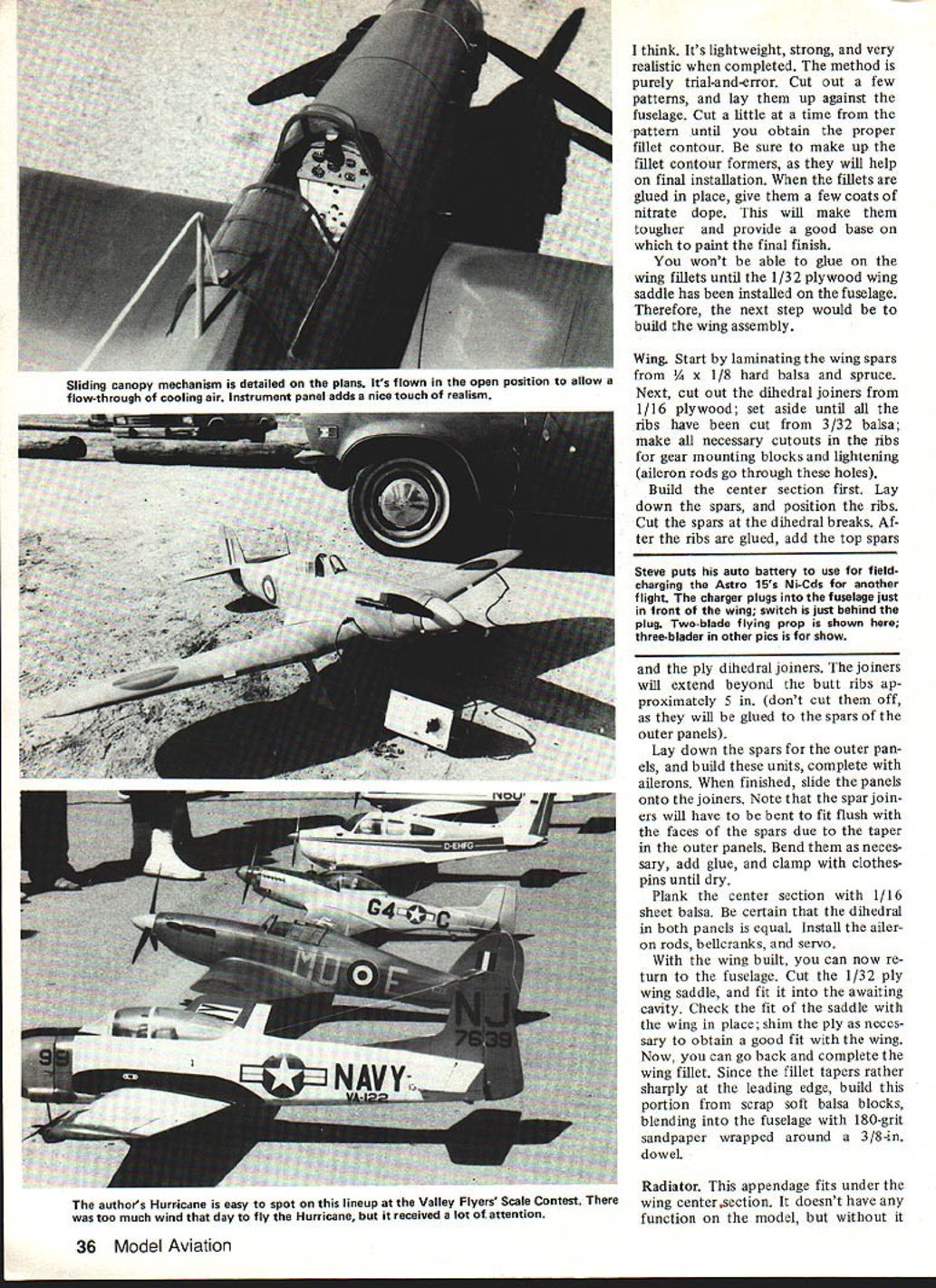
Canopy
The original model was constructed with a sliding canopy to serve two purposes. One was to vent warm air from the fuselage. The other was to allow access to the servos which were mounted three‑abreast on a ply plate along with a two-position switch for motor control.
The method I used for making the sliding canopy involved two lengths of 3/32-in. aluminum tubing for rails, mounted in the fuselage sides. They were split down the middle with a 1/16-in. slot on one side only; 1/16-in.-dia. brass tubing, mounted to the canopy section and slipped into the aluminum tubing, was used for the guides. I used pins inserted into the brass tubing, soldered and bent to a 90‑deg. angle; the pins acted as mounting points for the lower edge of the canopy. The idea worked well for me, but there may be other methods that the builder would prefer.
If you use the sliding canopy, don't install it until the ship is completed. There is a small 1/32-in. ply former that gets glued to the front of the canopy; once it is installed, the canopy can't be removed. The canopy frame was masked and sprayed with olive drab dope before installation.
Landing gear
Using the pattern shown on the front view of the plan, bend the main gear from 1/8-in. music wire. Bend the sway braces from 1/16-in. music wire, then bind and solder the braces to the main gear legs. I used wire soldering lugs on the ends of the sway braces to mount them to the ply gear braces (in the wing) with small wood screws. The main gear is mounted to the gear blocks with aluminum straps and screws.
The gear fairing doors are of .050 ASA plastic. Small metal strips soldered to the gear legs hold on the gear doors by means of 2-56 screws through small holes drilled in the straps and gear doors.
The tail wheel is held on with a Du-Bro wheel collar. Study the plans. A steering arm soldered to the top collar picks up the rudder cable for steering.
The engine cowl can be carved from balsa, laid-up in fiberglass, or pulled from plastic. The cowl on my model was made from ASA plastic pulled over a wooden pattern. The cockpit canopy was made in the same way. There isn't really a lot of effort in carving a plug, so if you have access to a vacu-form machine, give it a try. Make the exhaust manifolds from scrap soft balsa; apply sanding sealer, and finish with flat black paint.
Finishing and Covering
Since I was trying to keep the model's weight low, I chose to cover mine with MonoKote. I tried to find the flat-finish type mentioned in Don Srull's Spitfire article, but I had no luck. I ended up with the glossy stuff, which I painted with flat Pactra Formula U.
I covered the fuselage with silk. It gets around the compound curves easily, and the weight it adds is negligible; the fuselage was given four coats of nitrate dope. The final finish was a light coat of Formula U olive drab, followed by a light coat of camouflage flat tan. Before painting, I wiped the MonoKote areas with acetone to remove any oil or dirt. Decals produced by Dave Platt Models are very close to the proper size for this model.
Control rods
I used Sullivan Gold-N-Rod, cable type. These are lightweight, flexible, and can be easily positioned through the fuselage bulkheads. The cable system for moving the elevator and rudder makes a very neat installation. I like to attach the cable to the servo arms with either Du‑Bro or Goldberg easy connectors. To rig the controls with this setup, all I need to do is loosen the screw on the connector and move the cable fore and aft to get the desired result.
Flying and Preflight
Did you get everything lined up properly? Do the wing tips have the correct amount of washout? Are all the control attachment points secure? Are the wheels on tight? Don't laugh. I've seen many a new ship leave a wheel rolling down the runway as it lifted off, because a pre‑flight check was overlooked. It only takes one small item to destroy three or four months of work.
Check the balance point. It should fall between 25% and 30% of the wing chord. Don't fly if the ship is tail-heavy. A rearward balance point is courting a snap-roll and disaster. Be sure the CG is at the correct point.
My model was tested with a 13-in.-dia., 8-in.-pitch prop. It did very well once it was trimmed out. Later I tried a 12‑8, but the 13‑incher seemed to put out much more thrust. Even with the 530 sq. in. wing area, the model handles the 4-1/2-lb. total weight with ease. During the test flights, the motor battery was closely watched. I was a bit concerned that it might heat up too much, but it seems to stay very cool.
I believe the Hurricane would really perform with one of the new Cobalt motors. Maybe I'll try one later, but for now, I'm having a ball with a straight Astro 15 and the gear unit.
I don't think you will have any regrets if you build this ship. I took my Hurricane to the Valley Flyers Contest (in California), and it stole the show. If you're looking for a fun scale project, this one has great looks and flyability.
SAFE FLYING IS NO ACCIDENT
Specifications
- Wingspan: 60 in.
- Fuselage length: 48 in.
- Height: 15 in.
- Wing area: 530 sq. in.
- Wing loading: 20 oz./sq. ft.
- Weight: 4½ lb.
- Power: Geared Astro 15
- Radio: Futaba, 6 ch.
- Servos: Four, Futaba S‑20
- Prop: 13 x 8
- Canopy: .040 butyrate plastic
- Cowl: .050 ASA plastic
- Main wheels: Robart, 3¼ in.
- Tail wheel: Robart, 1 in.
- Spinner: Du‑Bro, 3 in.
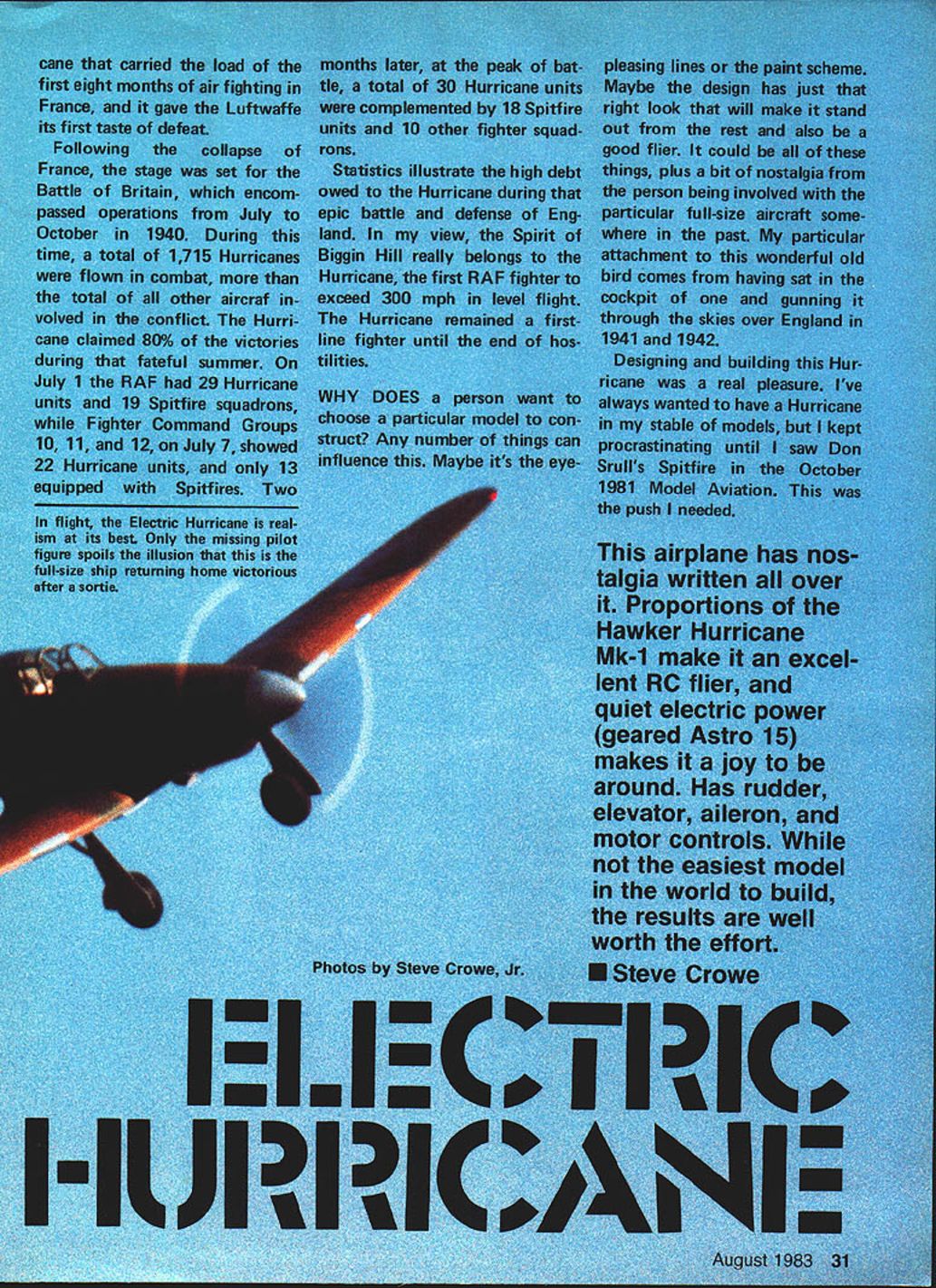
In these two pictures, it could be sitting on the tarmac waiting for action. With its thick wing, robust look, and camouflage paint scheme, it looks good from any angle. Flying surfaces were covered with MonoKote, fuselage with silk.
The finished and assembled framework seems too beautiful to cover—but then it gets even more beautiful when it is covered, finished, and decorated. Could pass for a huge rubber model.
Transcribed from original scans by AI. Minor OCR errors may remain.

